 HERCULES HE34 SDS-Max Type Rotary Hammer Owner’s Manual
IMPORTANT SAFETY INFORMATION
GENERAL POWER TOOL SAFETY WARNINGS
![]() Warning
Warning
Read all safety warnings and all instructions.
Failure to follow the warnings and instructions may result in electric shock, fire and/or serious injury.
Save all warnings and instructions for future reference.
The term ″power tool″ in the warnings refers to your mains-operated (corded) power tool.
Work area safety
- Keep work area clean and well lit.
Cluttered or dark areas invite accidents. - Do not operate power tools in explosive atmospheres, such as in the presence of flammable liquids, gases or dust. Power tools create sparks which may ignite the dust or fumes.
- Keep children and bystanders away while operating a power tool.
Distractions can cause you to lose control.
Electrical safety
- Power tool plugs must match the outlet.
Never modify the plug in any way.
Do not use any adapter plugs with grounded power tools. Unmodified plugs and matching outlets will reduce risk of electric shock. - Avoid body contact with grounded surfaces such as pipes, radiators, ranges and refrigerators. There is an increased risk of electric shock if your body is grounded.
- Do not expose power tools to rain or wet conditions. Water entering a power tool will increase the risk of electric shock.
- Do not abuse the cord. Never use the cord for carrying, pulling or unplugging the power tool. Keep cord away from heat, oil, sharp edges or moving parts. Damaged or entangled cords increase the risk of electric shock.
- When operating a power tool outdoors, use an extension cord suitable for outdoor use. Use of a cord suitable for outdoor use reduces the risk of electric shock.
- If operating a power tool in a damp location is unavoidable, use a Ground Fault Circuit Interrupter (GFCI) protected supply.
Use of a GFCI reduces the risk of electric shock.
Personal safety
- Stay alert, watch what you are doing and use common sense when operating a power tool.
Do not use a power tool while you are tired or under the influence of drugs, alcohol or medication. A moment of inattention while operating power tools may result in serious personal injury. - Use personal protective equipment. Always wear eye protection. Protective equipment such as dust mask, non-skid safety shoes, hard hat, or hearing protection used for appropriate conditions will reduce personal injuries.
- Prevent unintentional starting. Ensure the switch is in the off-position before connecting to power source and/or battery pack, picking up or carrying the tool. Carrying power tools with your finger on the switch or energizing power tools that have the switch on invites accidents.
- Remove any adjusting key or wrench before turning the power tool on. A wrench or a key left attached to a rotating part of the power tool may result in personal injury.
- Do not overreach. Keep proper footing and balance at all times. This enables better control of the power tool in unexpected situations.
- Dress properly. Do not wear loose clothing or jeweler. Keep your hair, clothing and gloves away from moving parts. Loose clothes, jewellery or long hair can be caught in moving parts.
- If devices are provided for the connection of dust extraction and collection facilities, ensure these are connected and properly used. Use of dust collection can reduce dust-related hazards. 8. Only use safety equipment that has been approved by an appropriate standards agency. Unapproved safety equipment may not provide adequate protection. Eye protection must be ANSI-approved and breathing protection must be NIOSH-approved for the specific hazards in the work area.
Power tool use and care
- Do not force the power tool. Use the correct power tool for your application.
The correct power tool will do the job better and safer at the rate for which it was designed. - Do not use the power tool if the switch does not turn it on and off.
Any power tool that cannot be controlled with the Trigger is dangerous and must be repaired. - Disconnect the plug from the power source before making any adjustments, changing accessories, or storing power tools.
Such preventive safety measures reduce the risk of starting the power tool accidentally. - Store idle power tools out of the reach of children and do not allow persons unfamiliar with the power tool or these instructions to operate the power tool. Power tools are dangerous in the hands of untrained users.
- Maintain power tools. Check for misalignment or binding of moving parts, breakage of parts and any other condition that may affect the power tool’s operation. If damaged, have the power tool repaired before use. Many accidents are caused by poorly maintained power tools.
- Keep cutting tools sharp and clean. Properly maintained cutting tools with sharp cutting edges
are less likely to bind and are easier to control. - Use the power tool, accessories and tool bits etc. in accordance with these instructions, taking into account the working conditions and the work to be performed. Use of the power tool for operations different from those intended could result in a hazardous situation.
Service
Have your power tool serviced by a qualified repair person using only identical replacement parts.
This will ensure that the safety of the power tool is maintained.
Percussion Hammer Safety Warnings
- Wear ear protectors. Exposure to noise can cause hearing loss.
- Use auxiliary handles if supplied with the tool. Loss of control can cause personal injury.
- Hold power tools by insulated gripping surfaces when performing an operation where the cutting tool may contact hidden wiring or its own cord. Contact with a “live” wire may make exposed metal parts of the tool “live” and could give the operator an electric shock.
- Keep clear of moving parts.
- Unplug before inspecting, removing or installing bit, or performing any service.
- Pull on bit after installation and before use; bit may move but MUST NOT slide out.
- Wear steel-toed boots during use.
- Do not operate this tool if you have back, neck, or wrist injuries, or other conditions that will be aggravated by the severe jerking forces that this tool exerts upon the operator.
- Maintain labels and nameplates on the tool. These carry important safety information. If unreadable or missing, contact Harbor Freight Tools for a replacement.
- Avoid unintentional starting. Prepare to begin work before turning on the tool.
- Do not lay the tool down until it has come to a complete stop. Moving parts can grab the surface and pull the tool out of your control.
- When using a handheld power tool, maintain a firm grip on the tool with both hands to resist starting torque.
- Do not leave the tool unattended when it is plugged into an electrical outlet. Turn off the tool, and unplug it from its electrical outlet before leaving.
- This product is not a toy. Keep it out of reach of children.
- People with pacemakers should consult their physician(s) before use. Electromagnetic fields in close proximity to heart pacemaker could cause pacemaker interference or pacemaker failure.
In addition, people with pacemakers should:- Avoid operating alone.
- Properly maintain and inspect to avoid electrical shock.
- Properly ground power cord. Ground Fault Circuit
Interrupter (GFCI) should also be implemented- it prevents sustained electrical shock.
- The warnings, precautions, and instructions discussed in this instruction manual cannot cover all possible conditions and situations that may occur.
It must be understood by the operator that common sense and caution are factors which cannot be built into this product, but must be supplied by the operator.
Vibration Safety
This tool vibrates during use. Repeated or long-term exposure to vibration may cause temporary or permanent physical injury, particularly to the hands, arms and shoulders. To reduce the risk of vibration-related injury:
- Anyone using vibrating tools regularly or for an extended period should first be examined by a doctor and then have regular medical check-ups to ensure medical problems are not being caused or worsened from use. Pregnant women or people who have impaired blood circulation to the hand, past hand injuries, nervous system disorders, diabetes, or Raynaud’s Disease should not use this tool. If you feel any medical or physical symptoms related to vibration (such as tingling, numbness, and white or blue fingers), seek medical advice as soon as possible.
- Do not smoke during use. Nicotine reduces the blood supply to the hands and fingers, increasing the risk of vibration-related injury.
- Use tools with the lowest vibration when there is a choice between different processes.
- Include vibration-free periods each day of work.
- Let the tool do the work.
- To reduce vibration, maintain the tool as explained in this manual. If any abnormal vibration occurs, stop use immediately.
![]() SAVE THESE INSTRUCTIONS
SAVE THESE INSTRUCTIONS
GROUNDING INSTRUCTIONS
![]() Warning
Warning
![]() TO PREVENT ELECTRIC SHOCK AND DEATH FROM INCORRECT GROUNDING WIRE CONNECTION:
TO PREVENT ELECTRIC SHOCK AND DEATH FROM INCORRECT GROUNDING WIRE CONNECTION:
Check with a qualified electrician if you are in doubt as to whether the outlet is properly grounded. Do not modify the power cord plug provided with the tool. Never remove the grounding prong from the plug. Do not use the tool if the power cord or plug is damaged. If damaged, have it repaired by a service facility before use. If the plug will not fit the outlet, have a proper outlet installed by a qualified electrician.
Double Insulated Tools: Tools with Two Prong Plugs
- Tools marked “Double Insulated” do not require grounding. They have a special double insulation system which satisfies OSHA requirements and complies with the applicable standards of Underwriters Laboratories, Inc., the Canadian Standard Association, and the National Electrical Code.
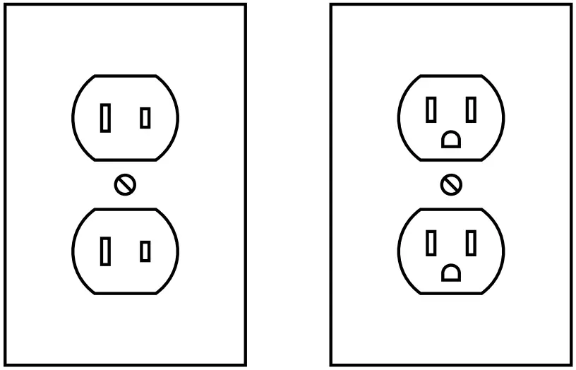
- Double insulated tools may be used in either of the 120 volt outlets shown in the following illustration.
(See Outlets for 2-Prong Plug.
Outlets for 2-Prong Plug
Extension Cords
- Grounded tools require a three wire extension cord.
Double Insulated tools can use either a two or three wire extension cord. - As the distance from the supply outlet increases, you must use a heavier gauge extension cord. Using extension cords with inadequately sized wire causes a serious drop in voltage, resulting in loss of power and possible tool damage. (See Table A.)
- The smaller the gauge number of the wire, the greater the capacity of the cord. For example, a 14 gauge cord can carry a higher current than a 16 gauge cord. (See Table A.)
- When using more than one extension cord to make up the total length, make sure each cord contains at least the minimum wire size required. (See Table A.)
- If you are using one extension cord for more than one tool, add the nameplate amperes and use the sum to determine the required minimum cord size. (See Table A.)
- If you are using an extension cord outdoors, make sure it is marked with the suffix “W-A” (“W” in Canada) to indicate it is acceptable for outdoor use.
- Make sure the extension cord is properly wired and in good electrical condition. Always replace a damaged extension cord or have it repaired by a qualified electrician before using it.
- Protect the extension cords from sharp objects, excessive heat, and damp or wet areas.
| TABLE A: RECOMMENDED MINIMUM WIRE GAUGE FOR EXTENSION CORDS* (120/240 VOLT) | |||||
| NAMEPLATE AMPERES (at full load) | EXTENSION CORD LENGTH | ||||
| 25´ | 50´ | 75´ | 100´ | 150´ | |
| 0 – 2.0 | 18 | 18 | 18 | 18 | 16 |
| 2.1 – 3.4 | 18 | 18 | 18 | 16 | 14 |
| 3.5 – 5.0 | 18 | 18 | 16 | 14 | 12 |
| 5.1 – 7.0 | 18 | 16 | 14 | 12 | 12 |
| 7.1 – 12.0 | 18 | 14 | 12 | 10 | – |
| 12.1 – 16.0 | 14 | 12 | 10 | – | – |
| 16.1 – 20.0 | 12 | 10 | – | – | – |
| Based on limiting the line voltage drop to five volts at 150% of the rated amperes. | |||||
Warning Symbols and Definitions
![]() This is the safety alert symbol. It is used to alert you to potential personal injury hazards. Obey all safety messages that follow this symbol to avoid possible injury or death.
This is the safety alert symbol. It is used to alert you to potential personal injury hazards. Obey all safety messages that follow this symbol to avoid possible injury or death.
![]() DANGER
DANGER
Indicates a hazardous situation which, if not avoided, will result in death or serious injury
![]() WARNING
WARNING
Indicates a hazardous situation which, if not avoided, could result in death or serious injury
![]() CAUTION
CAUTION
Indicates a hazardous situation which, if not avoided, could result in minor or moderate injury.
NOTICE
Addresses practices not related to personal injury.
Symbology
| Double Insulated |
| Volts |
| Alternating Current |
| Amperes |
n0 xxxx/min. | No Load Revolutions per Minute (RPM) |
| WARNING marking concerning Risk of Eye Injury. Wear ANSI-approved safety goggles with side shields. |
| Read the manual before set-up and/or use. |
| WARNING marking concerning Risk of Fire. Do not cover ventilation ducts. Keep flammable objects away. |
| WARNING marking concerning Risk of Electric Shock. Properly connect power cord to appropriate outlet. |
| WARNING marking concerning Risk of Hearing Loss. Wear hearing protection. |


Specifications
| Electrical Rating | 120VAC / 60Hz / 12A |
| Bit Type | 1-9/16″ (40mm) SDS-Max Type |
| Bits | 1 Bull Point Bit 1 Flat Bit |
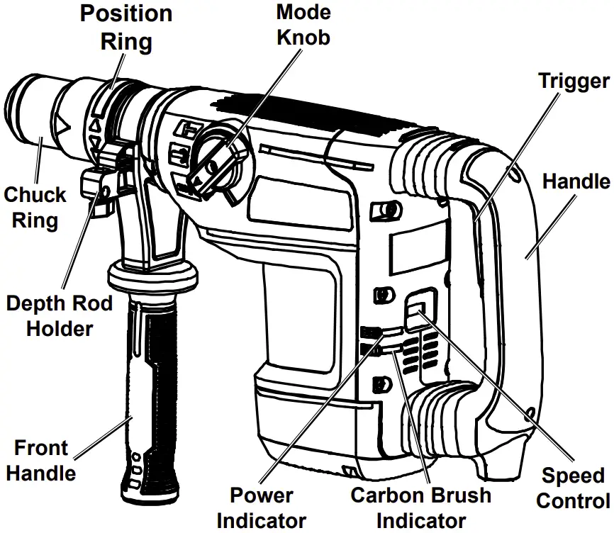
Functional Description
OPERATION
![]() Read the ENTIRE IMPORTANT SAFETY INFORMATION section at the beginning of this manual including all text under subheadings therein before set up or use of this product
Read the ENTIRE IMPORTANT SAFETY INFORMATION section at the beginning of this manual including all text under subheadings therein before set up or use of this product
Tool Set Up
![]() WARNING
WARNING
TO PREVENT SERIOUS INJURY FROM ACCIDENTAL OPERATION:
Make sure that the Trigger is in the off-position and unplug the tool from its electrical outlet before performing any procedure in this section.
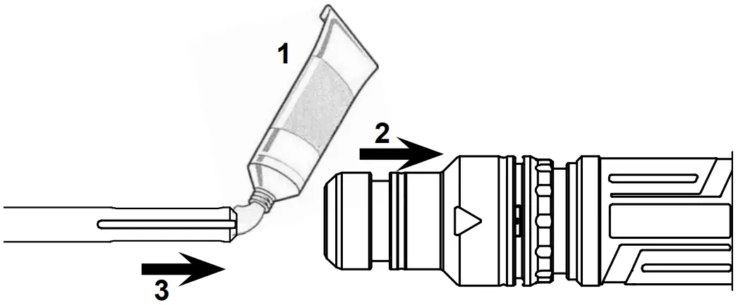
- Clean the loading end of the Bit to remove any debris, then lubricate the Bit with grease.
- Pull the Chuck Ring back and hold it.
- Insert the Bit while twisting it

- Release the Chuck Ring. If not, adjust the Bit until the Chuck Ring slides back into place.
- Physically check that the Bit is secure before operating. The Bit will have some play, but should not come out when pulled.
- To adjust the Front Handle, twist it to loosen it, rotate it as needed, and retighten it securely.
Workpiece and Work Area Set Up
- Designate a work area that is clean and well-lit.
The work area must not allow access by children or pets to prevent distraction and injury. - Route the power cord along a safe route to reach the work area without creating a tripping hazard or exposing the power cord to possible damage. The power cord must reach the work area with enough extra length to allow free movement while working.
- Secure loose work pieces using a vise or clamps (not included) to prevent movement while working.
- There must not be objects, such as utility lines, nearby that will present a hazard while working.
If working in the ground or on a concrete slab on the earth, call local utility company to ensure that area is clear of utility lines. - Protect power cord from crushing, abrasion, and scraping by broken rock or concrete.
- Keep power cord away from moving machines.
General Operation
![]() WARNING
WARNING
TO PREVENT SERIOUS INJURY:
Wear ANSI-approved safety goggles, ear protection, steel-toe boots, and dust mask during use.
Keep feet clear of Rotary Hammer.
Keep children and animals well clear of the work area.
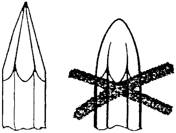
- Check Bit for dullness, cracks, or other damage.

CAUTION! Dull tipped bits can cause unnecessary bit movement, resulting in tool wear and possible injury. Use only sharp tipped bits. - Clearly mark the work area.
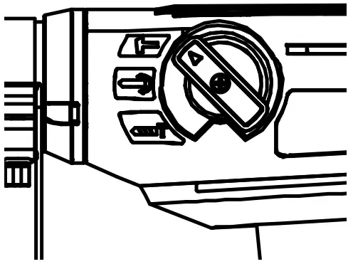
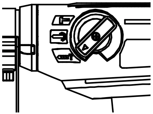
- Mode Knob – Set the Mode Knob to the required mode before using the tool.
NOTICE: TO PREVENT DAMAGE, do not change the Mode Knob while the tool is in operation. Make sure the Mode Knob is entirely in the desired position before use.- Hammer Mode
(top position)
The Bit will not rotate, but it will impact forwards and backwards.
Do not use this mode with spiral bits.
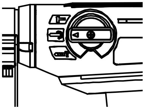
- Hammer/Drill Mode
(middle position)
The Bit will simultaneously rotate and impact. - bit Rotation Mode
(bottom position)
The Bit rotates. Use to adjust Bit to optimal position before switching back to Hammer
Mode or Hammer/Drill Mode. - Make sure that the Trigger is in the off-position, then plug the tool in.
- Set the bit against the work area.
CAUTION! Keep power cord away from moving machines. - Place one hand on the Front Handle and the other hand around the Handle.
- Press the upper part of the Trigger to start the tool.
Note: Trigger will lock on. Press the lower part of the Trigger to turn the tool off. - Push the tip forcibly down to begin striking material.
NOTICE: Running tool with no load or “empty blows” will damage the Rotary Hammer.
CAUTION! Once activated, do not bear down, or thrust forcibly against the work surface.
Note: If the Rotary Hammer has not been used for a long time or is being used in low temperatures, the tool may require 3-5 minutes to warm up.
NOTE: Carbon Brushes will wear during use. The Carbon brush Indicator will light if the brushes are worn. If the Carbon Brush Indicator lights, the worn Brushes will need to be replaced with the included Brushes by a qualified technician.
Note: During extended operation, periodically remove the bit and re-lubricate the loading end with grease. - If a different speed setting is needed, press the lower part of the Trigger, allow the tool to stop, and adjust the Speed Knob.
- When work is complete, press the lower part of the Trigger to turn the tool off.
- To prevent accidents, turn off the tool and disconnect its power supply after use.
- Clean, then store the tool indoors out of children’s reach.
- Hammer Mode
MAINTENANCE AND SERVICING
![]() Procedures not specifically explained in this manual must be performed only by a qualified technician.
Procedures not specifically explained in this manual must be performed only by a qualified technician.
![]() WARNING
WARNING
TO PREVENT SERIOUS INJURY FROM ACCIDENTAL OPERATION:
Make sure that the Trigger is in the off-position and unplug the tool from its electrical outlet before performing any procedure in this section.
TO PREVENT SERIOUS INJURY FROM TOOL FAILURE:
Do not use damaged equipment.
If abnormal noise or vibration occurs, have the problem corrected before further use.
Cleaning, Maintenance, and Lubrication
- BEFORE EACH USE, inspect the general condition of the tool. Check for:
- loose hardware
- misalignment or binding of moving parts
- cracked or broken parts
- damaged electrical wiring
- any other condition that may affect its safe operation.
- AFTER USE, wipe external surfaces of the tool with clean cloth.
- Store in temperatures no lower than 50-60°F.
NOTE: The Rotary Hammer has airtight construction, allowing long periods of use (approximately six months of regular usage) before lubrication.
Troubleshooting
| Problem | Possible Causes | Likely Solutions |
| Tool will not start. |
|
|
| Tool operates slowly. | Extension cord too long or wire size too small. | Eliminate use of extension cord. If an extension cord is needed, use shorter/heavier gauge cord. See Extension Cords in GROUNDING section. |
| Performance decreases over time. |
|
|
| Excessive noise or rattling. | Internal damage or wear. (Carbon brushes or bearings, for example.) | Have technician service tool. |
| Overheating. |
|
|
PLEASE READ THE FOLLOWING CAREFULLY
THE MANUFACTURER AND/OR DISTRIBUTOR HAS PROVIDED THE PARTS LIST AND ASSEMBLY DIAGRAM IN THIS MANUAL AS A REFERENCE TOOL ONLY. NEITHER THE MANUFACTURER OR DISTRIBUTOR MAKES ANY REPRESENTATION OR WARRANTY OF ANY KIND TO THE BUYER THAT HE OR SHE IS QUALIFIED TO MAKE ANY REPAIRS TO THE PRODUCT, OR THAT HE OR SHE IS QUALIFIED TO REPLACE ANY PARTS OF THE PRODUCT. IN FACT, THE MANUFACTURER AND/OR DISTRIBUTOR EXPRESSLY STATES THAT ALL REPAIRS AND PARTS REPLACEMENTS SHOULD BE UNDERTAKEN BY CERTIFIED AND LICENSED TECHNICIANS, AND NOT BY THE BUYER. THE BUYER ASSUMES ALL RISK AND LIABILITY ARISING OUT OF HIS OR HER REPAIRS TO THE ORIGINAL PRODUCT OR REPLACEMENT PARTS THERETO, OR ARISING OUT OF HIS OR HER INSTALLATION OF REPLACEMENT PARTS THERETO.
Record Product’s Serial Number Here:
Note: If product has no serial number, record month and year of purchase instead.
Note: Some parts are listed and shown for illustration purposes only, and are not available individually as replacement parts. Refer to UPC Specify UPC 792363568449 when ordering parts.
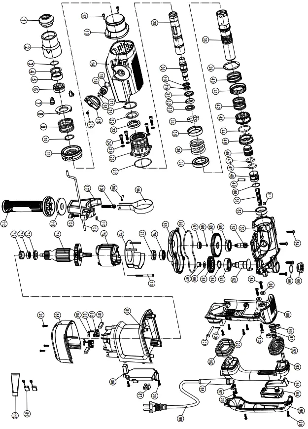
PARTS LIST AND DIAGRAM
Parts List
| Part | Description | Qty |
| 1 | Hammer Rod Protector | 1 |
| 2 | Chuck Ring | 1 |
| 3 | Retaining Ring Ø26 | 1 |
| 4 | Support Washer | 1 |
| 5 | Rubber Ring | 1 |
| 6 | Lock Bead Sheath | 1 |
| 7 | Insert Block | 2 |
| 8 | Spring Rack | 1 |
| 9 | Flex Sheath Spring | 1 |
| 10 | Retaining Ring Ø28 | 1 |
| 11 | Direction Selector | 1 |
| 12 | Hex Socket Bolt M4×16 | 2 |
| 13 | Front Shade | 1 |
| 14 | Cover | 1 |
| 15 | O Ring Ø13.94×Ø2.62 | 1 |
| 16 | Dial Staff Sheath | 1 |
| 17 | Spring | 1 |
| 18 | Mode Knob Spring | 1 |
| 19 | Mode Knob | 1 |
| 20 | Screw ST4.2×16 | 13 |
| 20A | Machine Screw M4×12 | 1 |
| 21 | Retaining Ring Ø42 | 1 |
| 22 | Woolen Ring Ø30×Ø42×3 | 1 |
| 23 | Oil Seal Ring Ø30xØ42×7 | 1 |
| 24 | Hex Socket Bolt M6×25 | 4 |
| 25 | Flat Washer Ø6×Ø10.5 | 4 |
| 26 | Front housing | 1 |
| 27 | O Ring Ø54.5×Ø2.2 | 1 |
| 28 | Hammer Staff Sheath | 1 |
| 30 | Impact Hammer | 1 |
| 31 | Hammer Ring | 1 |
| 32 | Vibration Reducing Cushion | 1 |
| 33 | Limit ring | 1 |
| 34 | Steel Ball SØ7.938 | 8 |
| 35 | Check Ring | 1 |
| 36 | Spring | 1 |
| 37 | Ball Bearing 6907RS | 1 |
| 38 | Cylinder | 1 |
| 39 | Ratchet Spring Ring | 1 |
| 40 | Ratchet Spring | 1 |
| 41 | Ratchet Ring | 1 |
| 42 | Clutch Spring | 1 |
| 43 | Clutch | 1 |
| 44 | Steel Wire Block Ring Ø32 | 1 |
| 45 | Big Cone-shaped Gear | 1 |
| 46 | Impact Piston | 1 |
| 47 | O Ring Ø21.1xØ3.5 | 2 |
| 48 | Gas Press Piston | 1 |
| 49 | Piston Pin | 1 |
| 50 | O Ring Ø22×Ø2 | 1 |
| 51 | Connecting Rod Asm. | 1 |
| 51.1 | Bushing | 1 |
| 52 | Oiliness Bearing Ø32×Ø37×12 | 1 |
| 53 | Crank Housing | 1 |
| 54 | Machine Screw ST5.5×25 | 8 |
| 55 | Oil Tank Cover | 1 |
| 56 | O Ring Ø25.12×Ø1.78 | 1 |
| Part | Description | Qty |
| 57 | Small Cone-shaped Gear | 1 |
| 58 | Ball Bearing 6904 VV | 1 |
| 59 | Final Gear | 1 |
| 60 | O Ring Ø5.5xØ1.05 | 1 |
| 61 | Ball Bearing 608 RS | 1 |
| 62 | Crank Shaft | 1 |
| 63 | Ball Bearing 6004 | 1 |
| 64 | Retaining Ring Ø20×1 | 1 |
| 65 | Crankshaft Gear | 1 |
| 66 | Crankshaft Gear Washer | 1 |
| 67 | Needle Bearing HK101410 | 1 |
| 68 | Seal Ring | 1 |
| 69 | Inner Cover | 1 |
| 70 | Ball Bearing NSK 6201 DDU | 1 |
| 71 | Oil Seal Ring Ø17×Ø32×7 | 1 |
| 72 | Fan Guide | 1 |
| 73 | Screw ST4.8×58 | 2 |
| 75 | Stator | 1 |
| 76 | Armature | 1 |
| 77 | Inductor | 1 |
| 78 | Ball Bearing NMB 608D | 1 |
| 79 | Bearing Ring | 1 |
| 80 | Housing | 1 |
| 81 | Carbon Brush | 2 |
| 82 | Carbon Brush Wire | 2 |
| 83 | Machine Screw ST3.5×16 | 4 |
| 84 | Coil Spring | 2 |
| 85 | Fan Cover | 1 |
| 86 | Speed Control | 1 |
| 87 | Dual Indicator Lens | 1 |
| 88 | Flat Washer Ø5.5xØ14×1.6 | 2 |
| 89 | Main Handle Seat | 1 |
| 90 | Shock Absorption Ferrule | 2 |
| 91 | Shock Absorption Spring | 1 |
| 92 | Shock Absorption Jacket | 1 |
| 93 | Main Handle | 1 |
| 94 | Trigger | 1 |
| 95 | Switch | 1 |
| 96 | Main Handle Cover | 1 |
| 97 | Cord Clip | 1 |
| 98 | Cord Armor | 1 |
| 99 | Cord | 1 |
| 100 | Ø2×14 Split Pin | 1 |
| 101 | Ø6×50 Shaft Pin | 1 |
| 102 | Bottom Shock Absorption Jacket | 1 |
| 103 | Hex Socket Bolt M6×20 | 2 |
| 104 | Side Handle Asm. Steel Tie | 1 |
| 105 | Spring Column Pin Ø5×23 | 1 |
| 106 | Ring Bolt | 1 |
| 107 | Side Handle Asm. Base | 1 |
| 108 | Wing Bolt | 1 |
| 109 | Depth Gauge | 1 |
| 110 | Nut M6 | 1 |
| 111 | Side Handle Cover | 1 |
| 112 | Side Handle | 1 |
| 115 | Grease Tube | 1 |
| 116 | Seal Ø15.5xØ23.2×3.3 | 2 |
Assembly Diagram
LIMITED 90 DAYS WARRANTY
Harbor Freight Tools Co. makes every effort to assure that its products meet high quality and durability standards, and warrants to the original purchaser that this product is free from defects in materials and workmanship for the period of 90 days from the date of purchase. This warranty does not apply to damage due directly or indirectly, to misuse, abuse, negligence or accidents, repairs or alterations outside our facilities, criminal activity, improper installation, normal wear and tear, or to lack of maintenance. We shall in no event be liable for death, injuries to persons or property, or for incidental, contingent, special or consequential damages arising from the use of our product. Some states do not allow the exclusion or limitation of incidental or consequential damages, so the above limitation of exclusion may not apply to you. THIS WARRANTY IS EXPRESSLY IN LIEU OF ALL OTHER WARRANTIES, EXPRESS OR IMPLIED, INCLUDING THE WARRANTIES OF MERCHANTABILITY AND FITNESS.
To take advantage of this warranty, the product or part must be returned to us with transportation charges prepaid. Proof of purchase date and an explanation of the complaint must accompany the merchandise. If our inspection verifies the defect, we will either repair or replace the product at our election or we may elect to refund the purchase price if we cannot readily and quickly provide you with a replacement. We will return repaired products at our expense, but if we determine there is no defect, or that the defect resulted from causes not within the scope of our warranty, then you must bear the cost of returning the product. This warranty gives you specific legal rights and you may also have other rights which vary from state to state.
Contact Us
Visit our website at: http://www.harborfreight.com
Email our technical support at: [email protected]
For technical questions, please call 1-888-866-5797
Copyright© 2021 by Harbor Freight Tools®. All rights reserved. No portion of this manual or any artwork contained herein may be reproduced in any shape or form without the express written consent of Harbor Freight Tools. Diagrams within this manual may not be drawn proportionally. Due to continuing improvements, actual product may differ slightly from the product described herein. Tools required for assembly and service may not be included.
26541 Agoura Road • Calabasas, CA 91302 • 1-888-866-5797