![]() USER’S OPERATING MANUAL FOR DIGITAL PROCESS
USER’S OPERATING MANUAL FOR DIGITAL PROCESS
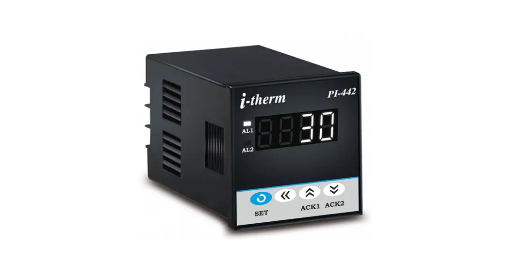
INDICATOR WITH ALARM
(Models:- PI – 442 / PI – 772 / PI – 882 / PI – 992)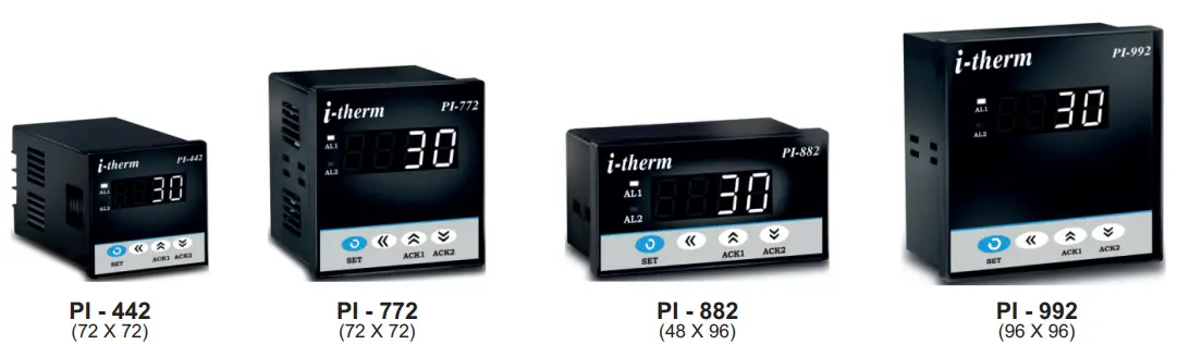
SPECIFICATIONS: –
- DISPLAY TYPE: 4-Digit 7 segment LED (WHITE)
Model no. PI-442 PI-882 PI-772 PI-992 Display height 0.36” 0.56” 0.56” 0.56” - INPUT
Sensor Input TC-J,K,R,S,N,T,B & RTD (PT-100) Analog Input 0 – 20mA, 4 – 20mA, 0 – 1VDC, 0 – 5VDC, 0 – 3.3VDC, 0 – 10VDC (Selectable) Range -1999 to 9999 Resolution 0.001, 0.01, 0.1 & 1°C (Selectable) Digital Filter 1 to 10 Selectable - OUTPUT: 2 Nos. Relay / SSR (Need to specify)
a) Relay OutputContact type N/O, CM, N/C Contact Rating 5A @ 250VAC or 30 VDC Life expectancy > 5,00,000 operations Isolation Inherent b) SSR Drive Output
Drive Capacity 12V @ 30mA. Isolation Non-Isolated. - FUNCTION: Both output work as Alarm
- ENVIRONMENTAL
Operating Range 0 ~50°C, 5~90% Rh Storage Humidity 95% Rh (Non-condensing) - POWER SUPPLY
Supply Voltage 90~270VAC, 50/60Hz. Consumption 4W Maximum. - PHYSICAL
Housing: ABS Plastic.
| Model no. | PI-442 | PI-882 | PI-772 | PI-992 |
| Weight (gms.) | 130 | 200 | 200 | 240 |
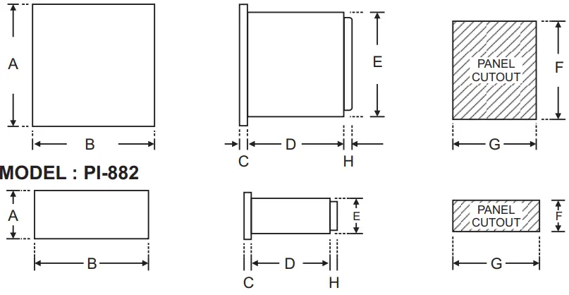
Over all Dimensions:-
| Dim Model | A | B | C | D | E | F | G | H |
| PI-442 | 48 | 48 | 8 | 75 | 43 | 44 | 44 | 9 |
| PI-772 | 72 | 72 | 10 | 65 | 66 | 68 | 68 | 9 |
| PI-992 | 96 | 96 | 10 | 45 | 89 | 92 | 92 | 9 |
| PI-882 | 48 | 96 | 10 | 45 | 43 | 44 | 92 | 9 |
SAFETY INSTRUCTION :-
GENERAL
- The controller must be configured correctly for intended operation. Incorrect configuration could result in damage to the equipment or the process under control or it may lead to personnel injury.
- The controller is generally part of control panel and in such a case the terminals should not remain accessible to the user after installation.
MECHANICAL
- The Controller in its installed state must not come in close proximity to any corrosive/combustible gases, caustic vapors, oils, steam or any other process by-products.
- The Controller in its installed state should not be exposed to carbon dust, salt air, direct sunlight or radiant heat
- Ambient temperature and relative humidity surrounding the controller must not exceed the maximum specified limit for proper operation of the controller.
ELECTRICAL
- The controller must be wired as per wiring diagram & it must comply with local electrical regulation.
- Circuit breaker or mains s/w with fuse (275V/1A) must be installed between power supply and supply terminals to protect the controller from any possible damage due to high voltage surges of extended duration.
- Circuit breaker and appropriate fuses must be used for driving high voltage loads to protect the controller from any possible damage due to short circuit on loads.
- To minimize pickup of electrical noise, the wiring for low voltage DC and sensor input must be routed away from high current power cables. Where it is impractical to do so, use shielded ground at both ends.
OVER ALL DIMENSIONS & PANEL CUT OUT (IN MM)
MODEL:-PI-442 / PI-772 / PI-992
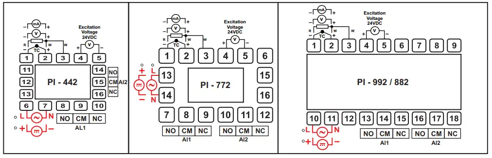
TERMINAL DIAGRAM:
PROGRAMMING:-
USER LIST:-
- To enter in this mode, Press and hold SET Once.
- Press UP or DOWN key to scroll between parameter options.
- Press SET key to store the current parameter & move on to the next parameter.
(All following selected parameter’s code shown in shaded will be displayed for 1 sec. followed by their values / options)
| PARA METER | DISPLAY | RANGE | DESCRIPTION | DEFAULT |
| Alarm 1 Set Point | 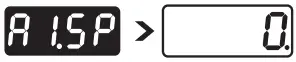 | LSPL ~ HSPL | User can change the ‘Alarm 1 Set point’ value using UP/ DOWN keys. Holding the key will change the value at a faster rate. Press SET key to store the desired value and move on to the next parameter. | 0 |
| Alarm 1 Band |  | 0 ~ 1000 | This parameter will appear only if, In Control list Alarm 1 type(A1.Ty) as Band Selected. User can change the ‘Alarm 1 Band’ value using UP/ DOWN keys. Press SET key to store the desired value and move on to the next parameter. For range limit as per resolution selected Ref. Table No.1(Page No. 4). | 0 |
| Alarm 2 Set Point |  | LSPL ~ HSPL | User can change the ‘Alarm 2 Set point’ value using UP/ DOWN keys. Holding the key will change the value at a faster rate. Press SET key to store the desired value and move on to the next parameter. | 0 |
| Alarm 2 Band |  | -02 ~ 50 | This parameter will appear only if, In Control list Alarm 2 type(A2.Ty) as Band Selected. User can change the ‘Alarm 2 Band’ value using UP/ DOWN keys. Press SET key to store the desired value and move on to the next parameter. For range limit as per resolution selected Ref. Table No.1(Page No. 4). | 0 |
CONTROL LIST:-
- To enter in this mode, Press and hold SET & DOWN key simultaneously for 3 sec.
- Press UP or DOWN key to scroll between parameter options.
- Press SET key to store the current parameter & move on to the next parameter.
(All following selected parameter’s code shown in shaded will be displayed for 1 sec. followed by their values / options)
| PARA METER | DISPLAY | DESCRIPTION | DEFAULT | |
| ALARM LOCK CODE |  | Set this parameter to 15 (Default LOCK CODE) to access Control List. User has a choice to set different Lock Code via USER LOCK CODE(U.LCk) in Configuration List. | 0 | |
| ALARM 1 TYPE | 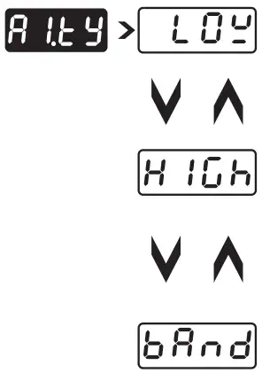 | Direct acting | Reverse acting | Low |
| Low Alarm:- Op1 activates when PV<A1.SP. 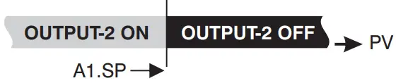 | Op1 activates when PV>A1.SP.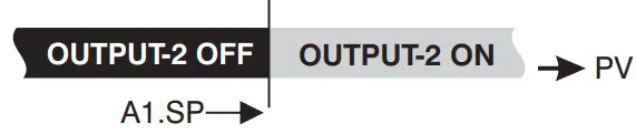 | |||
| High Alarm:- Op1 activates when PV>A1.SP.  | Op1 activates when PV<A1.SP.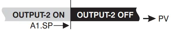 | |||
| Band Alarm:- OP1 activates when PV falls outside the Alarm 1 Band w.r.t. Alarm 1 Sei point in either direction. 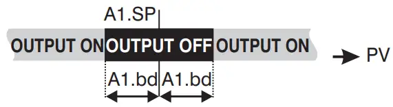 | OP1 activates when PV falls Inside the Alarm 1 Band w.r.t. Alarm 1 Sei point in either direction.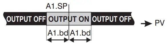 | |||
| ALARM 1 LOGIC | If this parameter is set as ‘Direct’, Relay/SSR energizes under Alarm condition & remains De-energized otherwise. ‘Direct’ setting is generally used for Audio/Visual Alarm Output. | Direct | ||
| If this parameter is set as ‘Reverse’, Relay/SSR De-energizes under Alarm condition & remains energized otherwise. ‘Reverse’ setting is generally used for tripping the process under Alarm condition. | ||||
| ALARM 1 INHIBIT | This parameter can be used to inhibit (suppress) the Alarm 1 activation upon power-up conditions by setting the parameter value to ‘YES”. From Power-up, the Alarm system remains disabled until PV is found with in the limits. | No | ||
| If Alarm 1 activation is desired even under Power-up condition, Set this parameter value to ‘NO’. | ||||
| ALARM 1 ACK. | Once Alarm 1 is activated, user has following three options to de-activate it. Auto:- When PV falls within the programmed limits, Alarm 1 will be de-activated automatically. | Auto | ||
| Manual:- Once Alarm 1 is activated, it remains activated until manually acknowledged by UP key. | ||||
| Both:- Once Alarm 1 is activated, it can be de-activated either by pressing UP key or when PV falls within the alarm limits. | ||||
| ALARM 1 Hysterisis | It sets the dead band between ON & OFF switching of the Output. Larger value of hysterisis minimize the number of ON-OFF operation of load. This increases life of actuators like contactors. For range limit as per resolution selected Ref. Table No.1(Page No. 4). | 2°C | ||
| ALARM 1 SET POINT | If Enabled, User can View & edit the Alarm 1 Set point (A1.SP) & Alarm 1 Band(A1.bd) in USER list. | Enable | ||
| If disabled, User can only View but can not edit Alarm 1 Set Point (A1.SP) & Alarm 1 Band(A1.bd) in USER list. | ||||
| ALARM 2 TYPE | Direct acting | Reverse acting | Low | |
| Low Alarm:- Op1 activates when PV<A2.SP. | Op1 activates when PV>A2.SP. | |||
| High Alarm:- Op1 activates when PV>A2.SP. | Op1 activates when PV<A2.SP. | |||
| and Alarm:- P1 activates when PV falls outside the Alarm 1 and w.r.t. Alarm 1 Sei point in either direction. | OP1 activates when PV falls Inside the Alarm 1 Band w.r.t. Alarm 1 Sei point in either direction. | |||
| ALARM 2 LOGIC | If this parameter is set as ‘Direct’, Relay/SSR energizes under Alarm condition & remains De-energized otherwise. ‘Direct’ setting is generally used for Audio/Visual Alarm Output. | Direct | ||
| If this parameter is set as ‘Reverse’, Relay/SSR De-energizes under Alarm condition & remains energized otherwise. ‘Reverse’ setting is generally used for tripping the process under Alarm condition. | ||||
| ALARM 2 INHIBIT | This parameter can be used to inhibit (suppress) the Alarm 1 activation upon power-up conditions by setting the parameter value to ‘YES”. From Power-up, the Alarm system remains disabled until PV is found with in the limits. | No | ||
| If Alarm 1 activation is desired even under Power-up condition, Set this parameter value to ‘NO’. | ||||
| ALARM 2 ACK. | Once Alarm 2 is activated, user has following three options to de-activate it. Auto:- When PV falls within the programmed limits, Alarm 2 will be de-activated automatically. | Auto | ||
| Manual:- Once Alarm 2 is activated, it remains activated until manually acknowledged by DN key. | ||||
| Both:- Once Alarm 2 is activated, it can be de-activated either by pressing DN key or when PV falls within the alarm limits. | ||||
| ALARM 2 Hysterisis |  | It sets the dead band between ON & OFF switching of the Output. Larger value of hysterisis minimize the number of ON-OFF operation of load. This increases life of actuators like contactors. For range limit as per resolution selected Ref. Table No.1(Page No. 4). | 2°C | |
| ALARM 2 SET POINT | 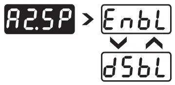 | If Enabled, User can View & edit the Alarm 2 Set point (A2.SP) & Alarm 2 Band(A2.bd) in USER list. | Enable | |
| If disabled, User can only View but can not edit Alarm 2 Set Point (A2.SP) & Alarm 2 Band(A2.bd) in USER list. | ||||
CONFIGURATION LIST:-
- To enter in this mode, Press and hold SET & UP key simultaneously for 3 sec.
- Press UP or DOWN key to scroll between parameter options.
- Press SET key to store the current parameter & move on to the next parameter.
(All following selected parameter’s code shown in shaded will be displayed for 1 sec. followed by their values / options)
| PARA METER | DISPLAY | DESCRIPTION | DEFAULT |
| CONFIG LOCK CODE |  | Set this parameter to 15 (Default LOCK CODE) to access Configuration List. User has a choice to set different Lock Code in the range 1 ~ 9999 via USER LOCK CODE in Configuration List. | 0 |
| Input Types | ‘TC-J’ :- If selected, instrument will accept temperature input from thermocouple J type sensor at rear terminal. Below range it will display ‘LLLL’ message & above range it will display ‘HHHH’. | TC-J | |
| ‘TC-K’ :- If selected, instrument will accept temperature input from thermocouple K type sensor at rear terminal. Below range it will display ‘LLLL’ message & above range it will display ‘HHHH’. | |||
| ‘TC-R’ :- If selected, instrument will accept temperature input from thermocouple R type sensor at rear terminal. Below range it will display ‘LLLL’ message & above range it will display ‘HHHH’. | |||
| ‘TC-S’ :- If selected, instrument will accept temperature input from thermocouple S type sensor at rear terminal. Below range it will display ‘LLLL’ message & above range it will display ‘HHHH’. | |||
| ‘TC-N’ :- If selected, instrument will accept temperature input from thermocouple N type sensor at rear terminal. Below range it will display ‘LLLL’ message & above range it will display ‘HHHH’. | |||
| TC-T’ :- If selected, instrument will accept temperature input from thermocouple N type sensot rear terminal. Below range it will display ‘LLLL’ message & above range it will display HHHH’. | |||
| ‘TC-B’ :- If selected, instrument will accept temperature input from thermocouple B type sensor at rear terminal. Below range it will display ‘LLLL’ message & above range it will display ‘HHHH’. | |||
| RTD’ :- If selected, instrument will accept temperature input from PT-100 sensor at rear erminal. Below range it will display ‘LLLL’ message & above range it will display ‘HHHH’. | |||
| ‘RTD.1′ :- If selected, instrument will accept temperature input from PT-100 sensor at rear terminal. Below range it will display ‘LLLL’ message & above range it will display ‘HHHH’. | |||
| ‘0 – 1′ :- If selected, instrument will accept 0 – 1VDC input at rear terminal. Below 0V it will display ‘LLLL’ message & above 1V it will display ‘HHHH’. | |||
| ‘0 – 3.3′ :- If selected, instrument will accept 0 – 3.3VDC input at rear terminal. Below 0V it will display ‘LLLL’ message & above 3.3V it will display ‘HHHH’. | |||
| ‘0 – 5′ :- If selected, instrument will accept 0 – 5 VDC input at rear terminal. Below 0V it will display ‘LLLL’ message & above 5V it will display ‘HHHH’. | |||
| ‘0 – 10′ :- If selected, instrument will accept 0 – 10VDC input at rear terminal. Below 0V it will display ‘LLLL’ message & Above 10V it will display ‘HHHH’. | |||
| ‘0 – 20′ :- If selected, instrument will accept 0 – 20 mA input at rear terminal. Below 0 mA it will display ‘LLLL’ message & Above 20 mA it will display ‘HHHH’. | |||
| ‘4 – 20′ :- If selected, instrument will accept 4 – 20mA input at rear terminal. Below 3.8mA it will display ‘LLLL’ message & Above 20mA it will display ‘HHHH’. If input is less than 3.2mA it will display ‘L.BRK’(Loop Break) message. | |||
| RESOLUTION | This parameter will NOT be prompted when input type is selected as Thermocouple (TCJ,K,R & S). When input type selected is RTD then only “0 & 0.0″ resolution format will be available. By this parameter user can select four format of resolution only for analog input, i.e. “0.000, 0.00, 0.0, 0″. For range limit as per resolution selected Ref. Table No.1 (Page No. 6). | 0 | |
| LOWER SP LIMIT | Sets the minimum limit for set point adjustment. It can be set from minimum specified range of selected sensor to HSPL value. This parameter will only be prompted if Input type is thermocouple or RTD. | º0 C | |
| HIGHERSP LIMIT | Sets the maximum limit for set point adjustment. It can be set from LSPL value to maximum specified range of selected sensor.This parameter will only be prompted if Input type is thermocouple or RTD. | º400 C | |
| ANALOG INPUT LOW VALUE | By this parameter user can define Low scale for input signal. Which can be in between ‘-1999 to Ai.Hi’. For range limit as per resolution selected Ref. Table No.1(Page No. 6). | 0 | |
| ANALOG INPUT HIGH VALUE | By this parameter user can define HIGH scale for input signal. Which can be in between ‘Ai.Lo to 9999′. For range limit as per resolution selected Ref. Table No.1(Page No. 6). | 9999 | |
| Analog Input Logic | By this parameter user can select the logic of the Analog Input. ‘DIR’ :- If selected then the value will vary from Ai.Lo to Ai.Hi. | Dir | |
| ‘REV’ :- If selected then the value will vary from Ai.Hi to Ai.Lo. | |||
| PROCESS VALUE OFFSET | Function of this parameter is to add/subtract a constant value to the measured PV to obtain Final PV. For range limit as per resolution selected Ref. Table No.1(Page No. 6). | 0 | |
| INPUT FILTER | Controller is equipped with an adaptive digital filter which is used to filter out any xtraneous pulses on the PV. Filtered PV Value is used for all PV dependent functions. If V signal is fluctuating due to noise, increase the filter time constant value. | 4 | |
| USER LOCK CODE | Default USER LOCK CODE is 15 to access Control & Configuration List. User has a choice to set its own USER LOCK CODE between 1 to 9999, this is to prevent unauthorized access of Control & Configuration List. | 15 |
User Calibration List:-
- To enter in this mode, Press and hold SHIFT key simultaneously for 3 sec.
- Press UP or DOWN key to scroll between parameter options.
- Press SET key to store the current parameter & move on to the next parameter.
(All following selected parameter’s code shown in shaded will be displayed for 1 sec. followed by their values / options)
| PARA METER | DISPLAY | DESCRIPTION | DEFAULT |
| User Calib. Lock | Set this parameter to “7” (Default LOCK CODE) to access User Calibration List. | 7 | |
| Low Calib- ration | This parameter allows the user to program “Lower Calibration” values other than factory programed values. With the help of Up / Down Key “Low Calibration” can be adjusted (As per selected input apply Low mA/Volt at input terminal). | 0 | |
| High Calib- ration | This parameter allows the user to program “Higher calibration” values other than factory programed values. With the help of Up / Down Key “High Calibration” can be adjusted (As per selected input apply High mANolt at input terminal) | 9999 | |
| Factory Default | Yes:- If selected, User calibration will be canceled and instrument will run on factory set calibration values. No:- If selected, there is no effect on User Calibration and instrument will run as per User defined Calibration values. | No |
Table 1 :- Range of Different Sensor Types.
| Sensor Type | Range | Resolution | Accuracy |
| Fe-k(J) T/C | 0 ~ 760°C | 1 °C | |
| Cr-AL(K) T/C | -99 ~ 1300°C | 1 °C | |
| (R)T/C | 0 ~1700°C | 1 °C | |
| (S)T/C | 0 ~1700°C | 1 °C | |
| TC – N | -99 ~1300°C | 1 °C | |
| TC – T | -99 ~ 400°C | 1 °C | |
| TC – B | 0 ~ 1800°C | 1 °C | |
| Pt-100(RTD) | -100 ~ 450°C | 1 °C | |
| Pt-100(RTD 0.1) | -100.0 ~ 450.0°C | 0.1 °C | ± 0.3 °C |
Table 2 :- Range as per Resolution.
| Resolution | Analog Input Low Value | Analog Input High Value | Process Value Offset | Alarm 1 Band | Alarm 2 Band | ALARM 1 Hysterisis | ALARM 2 Hysterisis |
| 0 | -1999 to 9999 | -1999 to 9999 | -25 to 25 | -50 to 50 | -50 to 50 | 1 to 25 | 1 to 25 |
| 0 | -199.9 to 999.9 | -199.9 to 999.9 | -25.0 to 25.0 | -50.0 to 50.0 | -50.0 to 50.0 | 0.1 to 25.0 | 0.1 to 25.0 |
| 0 | -19.99 to 99.99 | -19.99 to 99.99 | -15.00 to 25.00 | -19.00 to 50.00 | -19.00 to 50.00 | 0.01 to 25.00 | 0.01 to 25.00 |
| 0 | -1.999 to 9.999 | -1.999 to 9.999 | -1.900 to 5.000 | -1.900 to 5.000 | -1.900 to 5.000 | 0.001 to 2.500 | 0.001 to 2.500 |
Error Message:-
| Display Message | Selected Input | Descriptions |
| “OPEN” | TC-J,K,R,S,N,B or RTD | Open Circuit of Control Sensor |
| “HHHH” | 0 – 20 / 4 – 20 / 0-10 | If input is above range it will display “HHHH” message. |
| “LLLL” | -0 10/ | If input is below ‘0’ it will display “LLLL” message. |
| “LLLL” | 4 – 20 | If input is below “3.8mA” and above “3.2mA” it will display “LLLL” message. |
| “L.BRK” | 4 – 20 | If input is less than “3.2mA” it will display “L.BRK” (Loop Break) message. |
| “C.E.R.R.” | Any Input Selected | The device is out of calibration and need to be sent to factory for re-calibration. |
![]() Mfgd by: Innovative Instruments & Controls LLP
Mfgd by: Innovative Instruments & Controls LLP
338, New Sonal Link Service Industrial Premises Co-op Society Ltd,
Building No.2, Link Road, Malad (W), Mumbai – 400064.
Tel: 022-66939916/17/18;
E-mail : [email protected]
Website : www.itherm.co.in https://www.youtube.com/channel/UCzWGtv0HuHUgZR4KKRyKG1w/videos


