
![]()
USER MANUAL
WHEELED DUMPER

ZI-RD300 EAN : 9120039232485
![]()
![]() ATTENTION: Check engine oil!
ATTENTION: Check engine oil!
SAFETY SIGNS
SAFETY SIGNS DEFINITION OF SYMBOLS
| EC-CONFORM – This product complies with the EC directives. |
 | READ THE MANUAL! Read the user and maintenance manual carefully and get familiar with the controls in order to use the machine correctly and avoid injuries and machine defects. |
 | WARNUNG! Beachten Sie die Sicherheitssymbole! Die Nichtbeachtung der Vorschriften und Hinweise zum Einsatz der Maschine kann zu schweren Personenschäden und tödliche Gefahren mit sich bringen. |
 | Stop before any break and engine maintenance! |
 | General note |
 | Protective clothing! |
 | It is forbidden to remove the protection devices and safety devices. |
| Gasoline and oil are highly flammable and explosive! Do not smoke or have open flames near the machine! | |
 | Burn hazard! Keep away from hot parts on the machine! |
 | Solid Objects can be thrown away! |
 | Keep your hands and feet clear from all rotating parts! |
 | Keep a safe distance! |
 | Only for working outside! The exhaust fumes are dangerous, containing carbon monoxide. |
 | Tipping hazard! Do not operate on slopes with angles over 15° or tip loading at an inclined position. |
 | ATTENTION! For transport engine oil has been drained. Fill up with 4-stroke quality motor oil before the first operation! Failure to do so will result in permanent engine damage and a void guarantee. |
TECHNICS
3.1 components
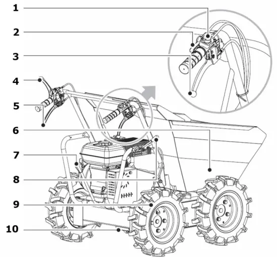
ZI-RD300
- engine switch
- throttle control
- right steering lever
- clutch control lever
- left steering lever
- dump box
- gear selection lever
- tipping handle
- wheel
- gearbox
3.1 Delivery content
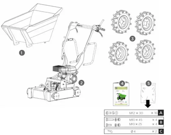
- dump box
- mainframe
- uedas (4 Unidades)
- manual
- hardware bag

technical data
ZI-RD300
| engine | 1 Zylinder 4-Takt OHV Motor G200F |
| engine power | 4,1 kW (bei 3600min -1 ) |
| displacement | 196 cm³ |
| transmission | 3 de Avance |
| Forward speed min/max | 1 / 6,4 km/h |
| Reverse speed min/max | 0,7 / 2 km/h |
| starter | recoil starter |
| speed max | 3600 min-1 |
| idle speed | 1400 min-1 |
| fuel | Unleaded fuel RON 95 |
| fuel tank capacity | 3,6 l |
| engine oil type | 15W40, SAE30, 15W40 |
| engine oil capacity | 0,6 l |
| gear oil type | 80W90, GL-5, GL-6, SAE80W-90 |
| gear oil capacity | 1,6 l |
| tires | 4.00-8 |
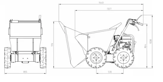
| dump box size | 912 x 650 x 560 mm |
| dump box capacity | 125 l |
| tilt function | Manual |
| load capacity max | 300 kg |
| weight | 145 kg |
| machine dimension | 1330 x 810 x 1038 mm |
| guaranteed sound power level | 98 dB(A) |
| vibration handlebar | 3.92 m/s2 k:1,5 m/s² |
Notice noise emission: The values given are emission values and therefore do not have to represent safe workplace values at the same time. Although there is a correlation between emission and immission levels, it cannot be reliably deduced whether additional precautions are necessary or not. Factors influencing the actual immission level at the workplace include the nature of the workspace and other noise sources, i.e. the number of machines and other adjacent operations. The permissible workplace values may also vary from country to country. However, this information should enable the user to make a better assessment of hazards and risks.
PREFACE
Dear Customer!
This manual contains important information and advice for the correct and safe use and maintenance of the wheeled dumper ZI-RD300. Following the usual commercial name of the device (see cover) is substituted in this manual with the name “machine”. The manual is part of the machine and may not be stored separately. Read it profoundly before
the first use of the machine and keep it for later reference. When the machine is handed to other persons always put the manual to the machine.
Please follow the security instructions!![]() Please read the entire manual, to prevent misunderstandings, machine damage, or even injuries! Due to the continuous development of our products illustrations, pictures might differ slightly. If you however find errors in this manual, please inform us. Technical changes excepted!
Please read the entire manual, to prevent misunderstandings, machine damage, or even injuries! Due to the continuous development of our products illustrations, pictures might differ slightly. If you however find errors in this manual, please inform us. Technical changes excepted!
Copyright law
© 2020
This manual is protected by copyright law – all rights reserved. Especially the reprinting as well as the translation and depiction of pictures will be prosecuted by law. The Court of jurisdiction is the Landesgericht Linz or the competent court for 4707 Schlüsslberg, AUSTRIA.
Customer Support
ZIPPER MASCHINEN GmbH
Gewerbepark 8, 4707 Schlüsslberg AUSTRIA
Tel.: +43 7248 61116-700
Fax: +43 7248 61116–720
Mail: [email protected]
SAFETY
26.1 Intended Use
The machine must only be used for its intended purpose! Any other use is deemed to be a case of misuse.
To use the machine properly you must also observe and follow all safety regulations, the assembly instructions, operating and maintenance instructions lay down in this manual.
All people who use and service the machine have to be acquainted with this manual and must be informed about the machine’s potential hazards.
It is also imperative to observe the accident prevention regulations in force in your area. The same applies to the general rules of occupational health and safety. The machine is used for: Small loading and transportation tasks in landscaping and agriculture. Any manipulation of the machine or its parts is a misuse, in this case, ZIPPER-MASCHINEN and its sales partners cannot be made liable for ANY direct or indirect damage. Even when the machine is used as prescribed it is still impossible to eliminate certain residual risk factors.
| WARNING |
|
Ambient conditions
The machine may be operated:
humidity………… max. 70%
temperature………. +5°С to +40°С (+41°F to +104°F)
Prohibited use
- The operation of the machine outside the stated technical limits described in this manual is forbidden.
- Operation of the machine function without any protection devices is forbidden.
- Any manipulation of the machine and parts is forbidden.
- The machine is not approved for transporting passengers
- The machine is not approved for public traffic!
- Etwaige Änderungen in der Konstruktion der Maschine sind unzulässig.
- The use of the machine for any purposes other than described in this user manual is forbidden.
- It is not allowed to leave the immediate work area during the work is being performed.!
26.2 Security instructions
Missing or non-readable security stickers have to be replaced immediately! To avoid malfunction, machine defects, and injuries, read the following security instructions!
The locally applicable laws and regulations may specify the minimum age of the operator and limit the use of this machine!
 |
|
|
|
 |
|
|
|
|
|
|
|
|
|
|
|
26.3 Remaining risk factors
| WARNING |
| It is important to ensure that each machine has remaining risks. In the execution of all work (even the simplest) greatest attention is required. A safe working depends on you! |
Even if the machine is used as required it is still impossible to eliminate certain residual risk factors totally. The following hazards may arise in connection with the machine´s construction and design:
- Risk of noise:
Working for a long time can damage your hearing if you do not use very good hearing protection. - Risks of working area:
Keep attention for stones and other things that can be thrown around by the machine. - Risk to the hands or fingers:
Risk of crushing: Operate the machine firmly with both hands. When tilting the dump box keep extreme caution.
Risk of burns: Access while it is working in the mowing apparatus. After the operation, the machine must cool down. Otherwise, there is an acute risk of scalding! - Risk of fire and explosion:
Gasoline is highly flammable and explosive under certain conditions. NEVER refuel fuel or engine oil while the machine is in operation or is hot. When refueling and at places where fuel is stored not smoke or allow open flames or sparks. Do not overfill the fuel tank and avoid the spillage of gasoline during refueling. If fuel is spilled make sure the area is completely dry and cleaned before starting the engine. Make sure that the filler cap is tightly closed again after refueling safely. - Chemical risks:
Never use or refuel a gasoline or diesel engine in a closed area without adequate ventilation. Carbon monoxide emissions from the internal drive units of the engine can cause in confined spaces through inhalation health effects and death. Therefore use the machine only in well-ventilated rooms or outdoors in operation. Liquid fuels can cause serious damage on the skin and the environment. - Vibration:
The declared vibration emission value has been for a standardized test is measured and can be used to compare one tool with another electric are. The declared vibration emission value may also be used for a preliminary assessment of exposure.
Warning:
The emission level of vibration can be different from the specified value during the actual use of the electric tool, depending on the manner in which the power tool is used. When you feel uncomfortable or notice discoloration of the skin on your hands during the use of the machine, stop working immediately. Observe sufficient break times to rest. Failure to have sufficient break times may result in a hand-arm vibration syndrome.
The extent of exposure depending on the type of work or machine use should be estimated and appropriate breaks are taken. In this way, the extent of exposure can be considerably reduced over the entire work time. Minimize the risk caused by vibrations. Maintain this machine according to the instructions in the manual.
These risk factors can be minimized through obeying all security and operation instructions, proper machine maintenance, proficient and appropriate operation by persons with technical knowledge and experience.
In spite of all safety is and remains her healthy common sense and their corresponding technical qualification/training for use of the machines most important safety factor!!
ASSEMBLY
Please check the product contents immediately after receipt for any eventual transport damage or missing parts. Claims from transport damage or missing parts must be placed immediately after initial machine receipt and unpacking before putting the machine into operation. Please understand that later claims cannot be accepted anymore.
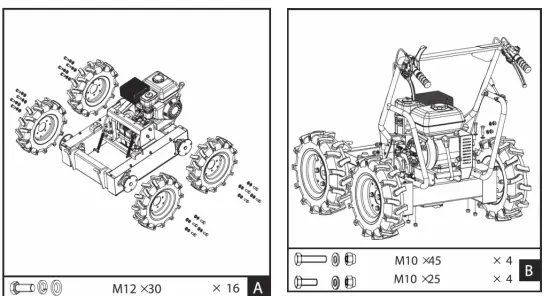
A Wheels:
Mount the wheels and fasten them with M12X30bolts, washers, and nuts.
B Handle frame:
Mount the handle frame assembly to the chassis and secure it with M10X25 bolts, washers, and nuts at the front and M10X45 bolts, washers, and nuts at the rear.
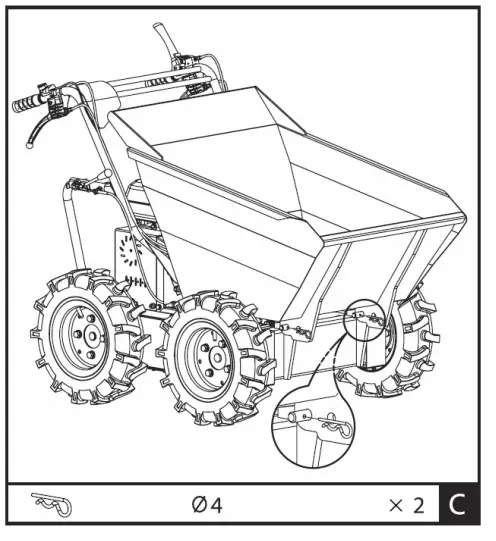
C Dump box:
Install the dump box and fasten the front with two Ø4 R-clips.
OPERATION
Device to be operated in a perfect state only. Inspect the device visually every time it is to be used. Check in particular the safety equipment, controls, and screwed connection for damage and if tightened properly. Replace any damaged parts before operating the device.
28.1 Operation instructions
| NOTICE |
|
28.2 Functions of components
- Engine switch: The engine switch must be in the ON position for the engine to run. Turning the engine switch to the OFF position stops the engine.
- Throttle control: Controls engine speed. Put the throttle control on low speed(L)or high speed(H)
- Right steering lever: Operate the lever to turn right
- Clutch control lever: Squeeze the lever, clutch engaged. Release the lever, clutch disengaged
- Left steering lever: Operate the lever to turn left
- Gear selection lever: Controls forward (3x) or reverse (1x) movements of the machine.
- Tipping handle: Controls the tipping of the dump box (manual!)
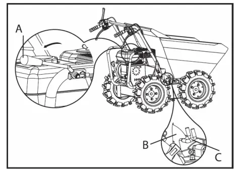
- Swing tipping handles A in the direction of the arrow to release the limiter Bout of hook C. The dump box will be released.
- Tipping by hand
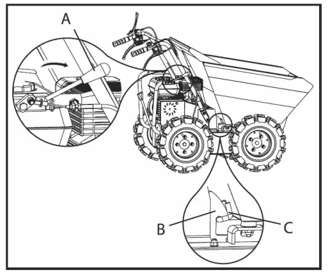
- After tipping the load, swing handle A back to reset limiter B into hook C, which will lock the dump box.
![]() Before starting operating, check the dump box to make sure it is locked (B, C)!
Before starting operating, check the dump box to make sure it is locked (B, C)!
28.3 Start up
28.3.1 Checking the engine oil level
| WARNING |
| ATTENTION! For transport, motor oil has been drained. Fill up with 4-stroke quality motor oil before the first operation! Failure to do so will result in permanent motor damage and avoid guarantee! |
| NOTICE |
| A too low oil level will cause damage to the engine and shorten the service life of the machine. Therefore, check the motor oil level before every start and if necessary fill up with oil. |
 | 1. To check the engine oil level, place the machine on a flat, level surface. Switch off the motor and wait for ten minutes to allow the circulating oil to collect in the oil pan. 2. Unscrew the oil dipstick and wipe with a clean, lint-free cloth or a non-fibrous paper towel. |
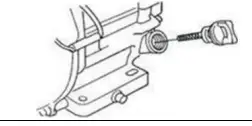 | 3. Push the dipstick back into the opening as far as possible, but do not screw it in. (Make sure that the dipstick is really pushed in completely – occasionally it gets jammed). |
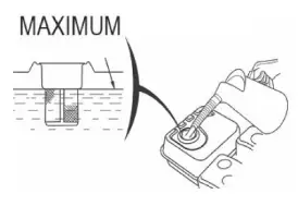
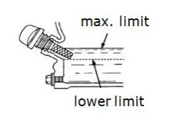 | 4. Pull out the oil dipstick again and check the oil level. There are two markings for this – see the illustration on the left. 5. If the oil level is low, fill up the recommended oil to the upper rim at the maximum (maximum filling volume: see technical data: do not overfill!) 6. Insert the oil dipstick again and retighten it. 7. Wipe away oil residues. |
28.3.2 Refuel
| WARNING | |
| Use only unleaded fuel with min. 95 octane or higher Never use a 2-stroke mixture of diesel! DAMAGE OF ENGINE | |
 |
|
28.4 Operation
28.4.1 Start Engine
Start the engine, if you have your wheeled dumper mounted correctly:
- Set the gear selection lever (7) to the neutral position.
- Move the choke lever on the machine to the full choke position.
- Turn the engine switch to “ON”.
- Pull the starter rope several times so that the carburetor is filled with gasoline.
- Pull the starter handle, pull out until resistance is felt. Let the rope rewind slowly across and then move expeditiously.
- Run the pull-starter handle slowly to the rope guide back as soon as the engine starts.
- Set the choke lever after a few seconds of engine run position ˝OPEN˝
To start the engine is warm the choke lever is not to be operated. - When the engine is warmed up, place the gear lever (7) (forward / reverse) in the desired position. If the desired gear can not load, press the clutch lever short and repeat the process. After inserting the gear lever Push the clutch lever and the mini transporter begins to drive. Drag to adjust the throttle lever to the speed accordingly.
- With the steering arm on the handles and can be easily controlled. To drive in the desired direction each uses the right or left steering lever.
28.4.2 Idle speed
Throttle lever to the “SLOW” (SLOWLY) take to protect the motor if no work is done. Downshifting the engine to idle prolongs the life of the engine reduces fuel consumption and the noise level of the machine.
28.4.3 Stop the engine
To stop the engine, release the clutch lever and turn the switch on the motor to the “OFF” position.
Under normal conditions, proceed as follows.
a. Move the throttle lever to the SLOW position.
b. Allow the engine to idle for 1-2 minutes.
c. Turn the engine switch to OFF “OFF”.
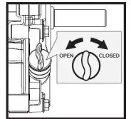
d. Turn the fuel valve lever to OFF.
ATTENTION: Not move the choke lever to stop the engine to CHOKE. Risk of reignition or damage to the engine!
NOTES
- The steering characteristics change proportional to the speed driven and the laden weight. The lightly loaded machine can be steered with a lighter lever operation. With greater loading of the steering lever to control with higher pressure.
- The highest loadings of mini handling is according to the floor on which the machine is used to adjust.
- It is therefore recommended to drive on difficult tracks in low gear and with caution. In such situations, the machine is to be driven over the entire range in low gear.
- Avoid sharp turns and frequent changes of direction when driving on the road, especially on rough, tough terrain, which has many sharp, uneven areas, causing high friction.
- Although the unit has 4-wheel traction, please remember, to be careful when working under adverse weather conditions (ice, rain, and snow) or on soils where the mini-dumper could be unstable.
- When the clutch lever is released, the machine is automatically braked and stops.
- If the machine is stopped on steep slopes, one of the wheels must be secured with a wedge.
MAINTENANCE
 | ATTENTION |
| No cleaning, upkeep, checks or maintenance when the machine is running Shut off the machine and let it cool down before starting servicing! |
The machine does not require intense maintenance. However, to ensure a long lifespan, we strongly recommend following the upkeep and maintenance plan.
Repairs must be carried out by specialists! Use original ZIPPER parts only!
NOTICE
Only properly maintained equipment may be a satisfactory tool. Care and maintenance deficiencies can cause unpredictable accidents and injuries. Repairs should be performed only by authorized service centers.
Improper operation may damage the equipment or endanger your safety.
29.1 Maintenance plan
| Controls for the maintenance of the machine | |
| Loose or lost screws, nuts, bolts | Regularly prior to each operation |
| Damage of any part of the machine | Regularly prior to each operation |
| The fuel tank of tightness | Regularly prior to each operation |
| Tires checking | Regularly prior to each operation |
| Machine cleaning | Regularly after operation |
| Cleaning spark plug | Every 25 working hours |
| Cleaning air filter | Every 20-30 working hours |
| Oil level checking | Every 50 working hours |
29.2 Cleaning
Clean the machine and the working attachment from soil, dust, grass, chips, small twigs, etc.
NOTICE
The use of solvents, harsh chemicals, or abrasive cleaners leads to damage to the machine! Therefore: When cleaning, use only mild detergent The use of high-pressure cleaners is not recommended. It shortens the service life and reduces the operational integrity. (Water can get into the gear!)
Impregnate bare surfaces of the machine against corrosion (e.g., anti-rust WD40)
29.3 Engine
Information about engine maintenance you can find in the operation manual of the engine manufacturer!
29.3.1 Engine oil exchange
The engine oil change would be explicitly mentioned here in order to be included in the machine operating manual. Oil change interval after the first 20h or 1 month after commissioning and then every 100h or 1x per year.
 | NOTICE |
| Waste oils are toxic and must not be released into the environment! Contact your local authorities for information on proper disposal. |
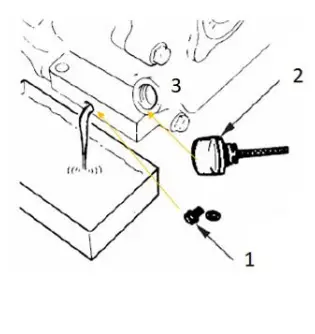 | 1. Remove the oil drain plug (1) from the engine. 2. Open the oil tank cap (2). Collect the draining oil in a collection container and dispose of it properly. 3. Retighten the oil drain plug after draining. 4. Fill in fresh oil through the filling opening (3) (see section Checking the engine oil level). 5. Use only high-quality engine oil, e.g: SAE30, 15W40, or similar! |
| NOTICE | |
| Drain the used oil when the engine is warm. Warm oil drains quickly and completely. |
29.4 Clutch
As the clutch wears out, the same lever could have a wider opening, being so uneasy to use. To enable proper operation, the clutch cable must be adjusted:
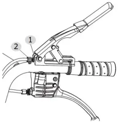 | 1. Loosen the jam nut (1) by turning it counterclockwise with a 10 mm wrench. 2. The clutch lever is set to the original position with the adjusting nut (2). 3. Then retighten the locknut (1). |
29.5 Steering
If you have difficulty steering the unit, you will need to adjust the steering levers with the special adjusters.
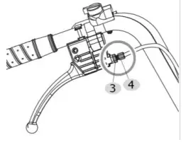 | 1. Loosen the jam nut (3) by turning it counterclockwise with 10 mm wrench. 2. Unscrew the adjusting nut (4) to eliminate the play in the cable, which can occur after initial use or normal wear. Be very careful not to unscrew the adjust nut too much because this can create another problem: the loss of traction. 3. Then retighten the locknut (3). |
If the above adjustment does not create enough cable tension, follow the steps below:
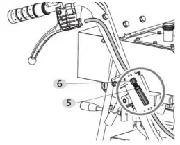 | 1. Loosen the jam nut (5) by turning it counterclockwise with a 10 mm wrench. 2. Unscrew the adjustment nut (6) to eliminate the play in the cable. (do not unscrew the adjust nut too much because this can create another problem: the loss of traction). 3. Retighten the locknut (5). |
29.6 Tires
Check the pressure of tires periodically to make sure they are properly inflated. Recommended pressure is: 2,1 bar (0,21Mpa)
29.7 Gearbox
29.7.1 Check gearbox oil
The gearbox is pre-lubricated and sealed at the factory. Unless there is evidence of leakage or service has been performed on the gearbox, no additional lubricate should be required until 50 hours of use. For future use, check the oil level after every 50 hours of use.
| NOTICE |
| Waste oils are toxic and must not be released into the environment! Contact your local authorities for information on proper disposal. |
If you remove the oil level plug and no oil flows out, please add oil and then screw the oil level plug.
NOTICE: recommended motor oil: GL-5, GL-6, SAE80W-90. Do not use synthetic oil! If you want to replace oil, place the machine on level ground. The machine must be stopped and still warm. Unscrew the filter cap and the drain plug. When the oil is drained, replace the drain plug, fill up with fresh oil and then replace the filter cap.
29.8 Storage
If the machine is stored for longer than 30 days:
- Let the machine cool down
- Clean the machine and dry
- Empty Tank and carburetor completely, avoid fuel spillage
- Store in a dry, reach of children’s place, well packaged
29.9 Disposal![]() Do not dispose of the machine, machine components fuel, and oil in residual waste. Contact your local authorities for information regarding the available disposal options. When you buy at your local dealer for a replacement unit, the latter is obliged to exchange your old one.
Do not dispose of the machine, machine components fuel, and oil in residual waste. Contact your local authorities for information regarding the available disposal options. When you buy at your local dealer for a replacement unit, the latter is obliged to exchange your old one.
TROUBLESHOOTING
| Trouble | Possible cause | Trouble |
| Engine will not start | Incorrect starting sequence | Observe the correct starting sequence |
| Dirty air filter | Clean/replace the air filter | |
| No fuel supply | Refuel | |
| Fault in the fuel line | Check the fuel line for kinks or damages | |
| Engine flooded. | Screw off, clean, and dry the spark plug. Then pull the cranking rope several times and reinstall the spark plug | |
| Spark plug connector not placed on. | Place on the spark plug connector | |
| No ignition spark | Clean/replace the spark plug Check ignition cable | |
| The engine starts and is stalled immediately | Incorrect idle adjustment | Contact customer service |
| The machine works with interruptions | Carburetor incorrectly adjusted | Contact customer service |
| Spark plug fouled | Clean/replace the spark plug Check spark plug connector | |
| The machine does not work with full performance | Machine overloaded | Too much pressure soil too tough |
| Dirty air filter | Clean/replace air filter | |
| Carburetor incorrectly adjusted | Contact customer service | |
| Machine does not run while the engine is running | The gear is not engaged properly | Shift lever in right position switch |
| NOTICE |
| Should you in necessary repairs not able to properly to perform or you have not the prescribed training for it always attract a workshop to fix the problem. |
SPARE PARTS
64.1 spare parts order
With original ZIPPER spare parts, you use parts that are attuned to each other to shorten the installation time and elongate the lifespan of your machine.
IMPORTANT
The installation of other than original spare parts voids the warranty!
So you always have to use original spare parts
When you place a spare parts order please use the service formula you can find in the last chapter of this manual. Always take a note of the machine type, spare parts number, and part name. We recommend copying the spare parts diagram and marking the spare part you need. You find the order address in the preface of this operation manual.
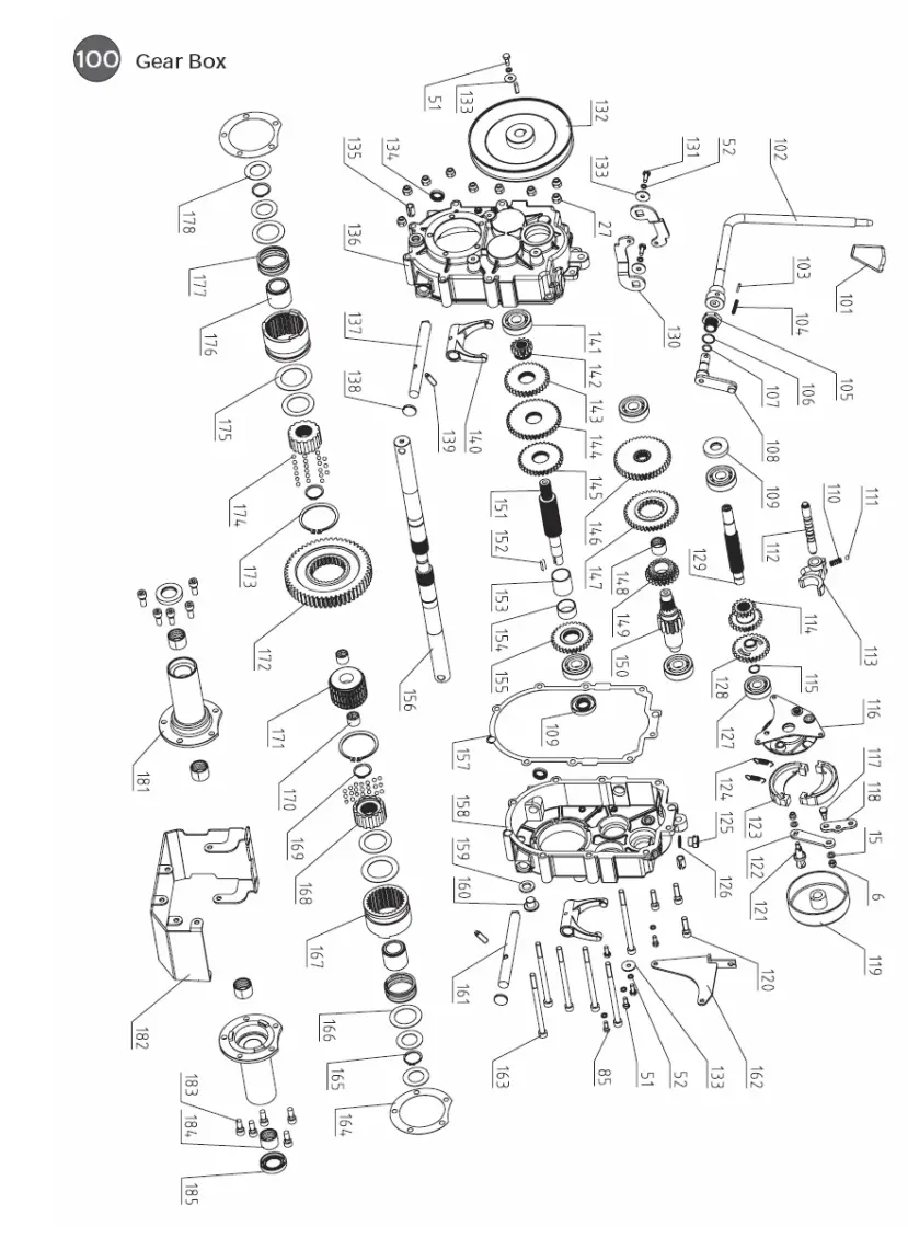
64.2 explosion drawing
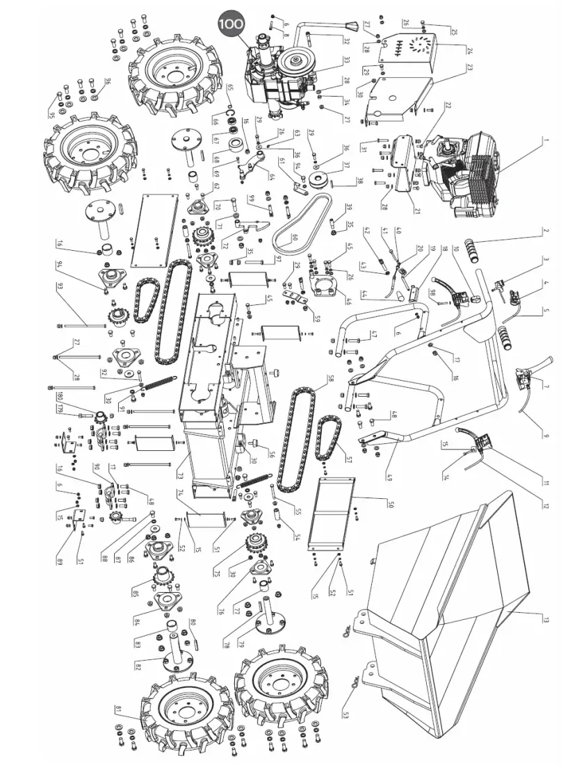
SPARE PARTS
| No | Description | Qty | No | Description | Qty |
| 1 | Engine | 1 | 52 | Spring Washer 6 | 18 |
| 2 | Handle Sleeve | 2 | 53 | Pin ∮4 | 2 |
| 3 | ON/OFF Switch | 1 | 54 | Chain Guide Posts | 2 |
| 4 | Throttle Lever | 1 | 55 | Bolt M8X70 | 2 |
| 5 | Throttle Cable | 1 | 56 | Screw M8X25 rubber pad screw | 2 |
| 6 | Locknut M6 | 12 | 57 | Chain 2 | 2 |
| 7 | Clutch Control Lever | 1 | 58 | Chain 1 | 2 |
| 8 | Bolt M6x20 | 2 | 59 | Pull Plate | 1 |
| 9 | Clutch Control Cable | 1 | 60 | B-Belt | 1 |
| 10 | Hoop | 2 | 61 | Belt Guide Weldment | 1 |
| 11 | Down Lever | 2 | 62 | Bolt M8X20 | 6 |
| 12 | Right/Left Steering Cable | 2 | 63 | Oil Nipple M6 | 1 |
| 13 | Box | 1 | 64 | Tensioner Pulley Bracket | 1 |
| 14 | Screw M6x55 | 1 | 65 | Circlip 15 | 1 |
| 15 | Washer 6 | 26 | 66 | Circlip 35 | 1 |
| 16 | Locknut M10 | 52 | 67 | Bearing 6202 | 2 |
| 17 | Washer 10 | 63 | 68 | Tensioner Pulley | 1 |
| 18 | Cable Plate | 1 | 69 | Bolt M6X25 | 1 |
| 19 | Rocker Lever | 1 | 70 | Bolt M12X65 | 1 |
| 20 | Dumper Box Cable | 1 | 71 | Flange Nut M12 | 1 |
| 21 | Mounting Base for Engine | 1 | 72 | Limiting Plate | 1 |
| 22 | Square Neck Bolt | 4 | 73 | Chassis | 1 |
| 23 | Pulley Front Cover | 1 | 74 | Fender | 4 |
| 24 | Pulley Back Cover | 1 | 75 | Rear Chain wheel | 2 |
| 25 | bolt M8X16 | 1 | 76 | Bearing 205 | 4 |
| 26 | Spring Washer 8 | 7 | 77 | Bush 2 | 2 |
| 27 | Lock Nut M8 | 36 | 78 | Flat Key A8X60 | 2 |
| 28 | Washer 8 | 49 | 79 | Rear Rim | 2 |
| 29 | Bolt M8X20 | 6 | 80 | Flat Key A10X60 | 2 |
| 30 | Flange Nut M8 | 6 | 81 | Wheel | 4 |
| 31 | Bolt M8X40 | 4 | 82 | Front Rim | 2 |
| 32 | Bolt M8X60 | 1 | 83 | Bush 1 | 4 |
| 33 | Gear Box | 1 | 84 | Bearing 305 | 4 |
| 34 | Bush | 1 | 85 | Front Rim | 2 |
| 35 | Flange Nut M10 | 3 | 86 | Washer 40×13.5×4 | 4 |
| 36 | Plain washers-large | 2 | 87 | Spring Washer 12 | 20 |
| 37 | Belt Pulley | 1 | 88 | Bolt M12X20 | 4 |
| 38 | Flat Key B5x40 | 1 | 89 | Small Connecting Plate | 2 |
| 39 | Belt Shaft | 1 | 90 | Wheel Axle Press Board | 2 |
| 40 | Circlip 8 | 1 | 91 | Spring | 2 |
| 41 | Rockshaft | 1 | 92 | Bolt M8X50 | 2 |
| 42 | Cable Fixed Pin 1 | 2 | 93 | Bolt M8X175 | 6 |
| 43 | Thin Nut M10 | 3 | 94 | Bolt M10X25 | 12 |
| 44 | Taper Knob | 1 | 95 | Bolt M12X30 | 16 |
| 45 | Bolt M8X25 | 5 | 96 | Washer 12 | 16 |
| 46 | Fixed Bracket | 1 | 97 | Bolt M10X70 | 1 |
| 47 | Bolt M10X45 | 4 | 98 | Screw M6X35 | 1 |
| 48 | Bolt M10X25 | 12 | 99 | Cable Fixed Pin 2 | 3 |
| 49 | Handle Frame Assembly | 1 | 179 | Screw M10x50 | 2 |
| 50 | Cover Weldment | 2 | 180 | Driving Wheel | 2 |
| 51 | Bolt M6X16 | 24 | |||
SPARE PARTS
SPARE PARTS
| No. | Description | Qty | No. | Description | Qty |
| 101 | Lever Knod | 1 | 143 | Gear Ⅱ-4 | 1 |
| 102 | Lever | 1 | 144 | Gear Ⅱ-3 | 1 |
| 103 | Pin 3X30 | 1 | 145 | Gear Ⅱ-2 | 1 |
| 104 | Pin 5×30 | 1 | 146 | Gear -Ⅲ-4 | 1 |
| 105 | Orientation Nut | 1 | 147 | Gear -Ⅲ-3 | 1 |
| 106 | O-Ring 17×1.8 | 1 | 148 | Gear Ⅲ-2 Bush | 1 |
| 107 | O-Ring 11.2×1.8 | 1 | 149 | Gear -Ⅲ-2 | 1 |
| 108 | Lever Mount Bracket | 1 | 150 | Gear Shaft Ⅲ | 1 |
| 109 | Seal FB17X47X7 | 1 | 151 | ShaftⅡ | 1 |
| 110 | Spring | 1 | 152 | Key C5x20 | 2 |
| 111 | Steel Ball 6 | 1 | 153 | Bush 1 | 1 |
| 112 | Gearshift Fork Shaft | 1 | 154 | Bush 2 | 1 |
| 113 | Gearshift Fork | 1 | 155 | Gear Ⅱ-1 | 1 |
| 114 | Slip Duplex Pulley | 1 | 156 | Output Shaft | 2 |
| 115 | Ciclip 15 | 1 | 157 | Output Gear Bush Gasket | 1 |
| 116 | Rivet Assembly | 1 | 158 | Gear Box Case ( L) | 1 |
| 117 | Joint Bolt | 1 | 159 | Washer Groupware 14 | 1 |
| 118 | Plate | 1 | 160 | Plug M14X1.5 | 1 |
| 119 | Expansion Brake Cover | 1 | 161 | Clutch Fork Shaft (L) | 1 |
| 120 | Bolt M8X30 | 3 | 162 | Cable Connecting Plate Weldment | 1 |
| 121 | Bolt | 1 | 163 | Bolt M8X130 | 6 |
| 122 | Brake Pull Plate | 1 | 164 | Output Gear Bush Gasket | 2 |
| 123 | Brake Disk | 2 | 165 | Clip 25 | 2 |
| 124 | Spring | 2 | 166 | Spring Gasket | 4 |
| 125 | Vent-Plug | 1 | 167 | Clutch Bush | 2 |
| 126 | Gasket | 1 | 168 | Joint Bush | 2 |
| 127 | Bearing 6302 | 1 | 169 | Clip 26 | 2 |
| 128 | Pulley | 1 | 170 | Joint Bush Composite Bushing | 2 |
| 129 | ShaftⅠ | 1 | 171 | Joint Bush | 1 |
| 130 | Swing Plate | 2 | 172 | Output Gear | 1 |
| 131 | Bolt M6x20 | 2 | 173 | Clip 58 | 2 |
| 132 | Pulley | 1 | 174 | Steel Ball 5 | 42 |
| 133 | 4 | 175 | Spring Gasket | 2 | |
| 134 | Seal FB16X22X4 | 2 | 176 | Spring Guide bush | 2 |
| 135 | Pin 12×20 | 2 | 177 | Clutch Spring | 2 |
| 136 | Gear Box Case ( R) | 1 | 178 | Gasket 1 | 4 |
| 137 | Clutch Fork Shaft ( R) | 1 | 181 | Output Shaft House | 2 |
| 138 | Plug | 2 | 182 | Guard Cover | 1 |
| 139 | Screw M8x25 | 2 | 183 | Bolt M8X20 | 10 |
| 140 | Clutch Fork Shaf | 2 | 184 | Output Shaft Composite Bushing | 4 |
| 141 | Bearing 6303 | 5 | 185 | Seal FB42X25X7 | 2 |
| 142 | Gear Ⅱ-5 | 1 |
WARRANTY GUIDELINES
- Warranty:
Company ZIPPER Maschinen GmbH grants mechanical and electrical components a warranty period of 2 years for amateur use; and a warranty period of 1 year for professional use, starting with the purchase of the final consumer. In case of defects during this period, which are not excluded by paragraph 3, ZIPPER will repair or replace the machine at its own discretion. - Report:
In order to check the legitimacy of warranty claims, the final consumer must contact his dealer. The dealer has to report in written form the occurred defect to ZIPPER. If the warranty claim is legitimate, ZIPPER will pick up the defective machine from the dealer. Returned shipping by dealers which have not been coordinated with ZIPPER, will not be accepted and refused. - Regulations:
a) Warranty claims will only be accepted, when a copy of the original invoice or cash voucher from the trading partner of ZIPPER is enclosed to the machine. The warranty claim expires if the accessories belonging to the machine are missing.
b) The warranty does not include free checking, maintenance, inspection or service works on the machine. Defects due to incorrect usage of the final consumer or his dealer will not be accepted as warranty claims either. Some examples: usage of wrong fuel, frost damage in water tanks, leaving fuel in the tank during the winter, etc.
c) Defects on wear parts are excluded, e.g. carbon brushes, collection bags, knives, cylinders, cutting blades, clutches, sealings, wheels, saw blades, splitting crosses, riving knives, riving knife extensions, hydraulic oils, oil/air/fuel filters, chains, spark plugs, sliding blocks, etc.
d) Also excluded are damages on the machine caused by incorrect or inappropriate usage, if it was used for a purpose which the machine is not supposed to, ignoring the user manual, force majeure, repairs or technical manipulations by not authorized workshops or by the customer himself, usage of non-original ZIPPER spare parts or accessories.
e) After inspection by our qualified personnel, resulting costs (like freight charges) and expenses for not legitimated warranty claims will be charged to the final customer or dealer.
f) In case of defective machines outside the warranty period, we will only repair them after advance payment or dealer’s invoice according to the cost estimate (incl. freight costs) of ZIPPER.
g) Warranty claims can only be granted for customers of an authorized ZIPPER dealer who directly purchased the machine from ZIPPER. These claims are not transferable in the case of multiple sales of the machine. - Claims for compensation and other liabilities:
The liability of company ZIPPER is limited to the value of goods in all cases. Claims for compensation because of poor performance, lack, damages or loss of earnings due to defects during the warranty period will not be accepted. ZIPPER insists on its right to the subsequent improvement of the machine.
Product experience form
We observe the quality of our delivered products in the frame of a Quality Management policy. Your opinion is essential for further product development and product choice. Please let us know about your:
- Impressions and suggestions for improvement.
- experiences that may be useful for other users and for product design
- Experiences with malfunctions that occur in specific operation modes
We would like to ask you to note down your experiences and observations and send them to us via FAX, E-Mail or by post:
My experiences:
| name : product : purchase date : purchased from : e-mail: Thank you for your kind cooperation! |
| CONTACT: Z.I.P.P.E.R MASCHINEN GmbH 4707 Schlüsslberg, Gewerbepark 8 AUSTRIA Tel :+43 7248 61116 700 Fax:+43 7248 61116 720 [email protected] |
SERVICE FORM
Please tick one box from below:
service inquiry
spare part inquiry
guarantee claim
1. senders information (* required)
- first name, family name………………………..
- street, house number……………………..
- ZIP code, place……………………………….
- country………………………………….
- (mobile) phone……………………..
- International numbers with country code…………………………………
- E-Mail………………………………….
- Fax……………………………………..
2. tool information
!serial number:……………………………..
‘machine type:…………………………………….
2.1 required spare parts
| Part No° | description | number |
problem description
Please describe amongst others the problem: What has caused the problem/defect, what was the last activity before you noticed the problem/defect?
For electrical problems: Have you had checked your electric supply and the machine already by a certified electrician?
Additional information
INCOMPLETELY FILLED SERVICE FORMS CAN NOT BE PROCESSED! FOR GUARANTEE CLAIMS PLEASE ADD A COPY OF YOUR ORIGINAL SALES / DELIVERY RECEIPT OTHERWISE IT CAN NOT BE ACCEPTED. FOR SPARE PART ORDERS PLEASE ADD TO THIS SERVICE FORM A COPY OF THE RESPECTIVE EXPLODED DRAWING WITH THE REQUIRED SPARE PARTS BEING MARKED CLEARLY AND UNMISTAKABLE. THIS HELPS US TO IDENTIFY THE REQUIRED SPARE PARTS FASTLY AND ACCEL-LERATES THE HANDLING OF YOUR INQUIRY.
THANK YOU FOR YOUR COOPERATION!
ZIPPER MASCHINEN GmbH
Gewerbepark 8
4707 SchlUsslberg I AUSTRIA
+43 (0) 7248 61116-700 1 FAX 7248 61116-720
[email protected] /www.zipper-maschinen.at


