HANSONG BM240 Amplifier Box User Manual
INTRODUCTION
General Product Description
The “BM240” is an amplifier box for built-in power supply ,It Can play optical source , bluetooth source and Aux source music. It includes a left and a right channel for stereo.There is a pair button and an indication of RGB lights.and a dial switch for selecting a different EQ .
Definitions, Acronyms, Symbols and Abbreviations
Abbreviation | Comment | Abbreviation | Comment |
| CRS | Customer requirements Specifications | dB | Decibel: Unit of Sound Level |
| EMC | Electro Magnetic Compatibility | Hz | Hertz: Unit of Frequency |
| LED | Light Emitting Diode | BSMI | Bureau of Standards, Metrology and Inspection |
| N/A | Not Applicable | SASO | Saudi Arabian Standards Organization |
| Oct | octave | NOM | Norma’s Officials Mexicans |
| TA | Type Approval | PC | Polycarbonate |
| TBC | To be confirmed | ABS | Acrylonitrile Butadiene Styrene |
| TBD | To be defined | POM | Polyoxymethylene |
| ID | Industrial Design | CE | Conformité Européenne |
| DV or DVT | Design Verification Test | FCC | Federal Communications Commission |
| DM or DMT | Design Maturity Test | ODM | Original Design Manufacturer |
| FM | Frequency Modulation | PSS&L | Product Safety, Security & Liability |
| RMS | Root Mean Square | 50N | 50 Newton |
| PHC | Power Handling Capacity | TR | Trial Run |
| RH | Relative Humidity | TCMF | Test Case Management File |
| ESD | Electro Static Discharge | PMPO | Peak Music Power Output |
| S/N | Signal to Noise Ratio | IEC | Intern. Electro technical Commission |
| THD | Total Harmonic Distortion | Fo | Resonance Frequency |
| EUT | Equipment Under Test | TPU | Thermo Plastic Urethane |
| SoC | Statement of Conformance | SPL | Sound Pressure Level |
| FR | Flame Retardants | HDMI | High-Definition Multimedia Interface |
| OEM | Original Equipment Manu fact. | HDCP | High-bandwidth Digital Content Protect. |
| & | Important remark | CEC | Consumer Electronics Control |
| FRS | Functional Requirement Specification |
Table 1 Definitions
General Product Overview
Front Panel:
- AUX input
- Optical input
- Service (softwear updata)
- BT/Pair button
- 100-240V~50/60Hz,80W (Power in)
Rear Panel:
- Dial switch(choose a different EQ)
- Output terminal( left and right)
Remote
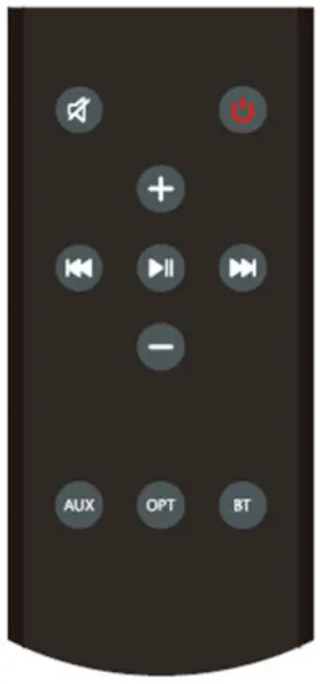
- Mute
- Power
- Volume up
- Last
- Pause
- Next
- Volume down
- Aux source
- Optical sourse
- BT source
- When pushing |<< on the remote for 2s BT pairing is turned OFF
- When pushing >>| on the remote for 2s BT pairing is turned ON
- When pushing the BT button on remote for 2s the device is disconnected from the phone currently paired with the BM240, this allows a change in who is connected via remote
Key Features and Performance
- Bluetooth input source, requires Distance greater than 10m in open distance.
- The pair bottom can set the bluetooth .
- The RGB LED indicate different states .
- Remote control. requires Distance greater than 10m in open distance.
Special connectors & modes.
Debug/Tuning connector
A 6 pin connector will be present on the PCBA to allow the connection to the MCU for Debug and Tuning purpose.
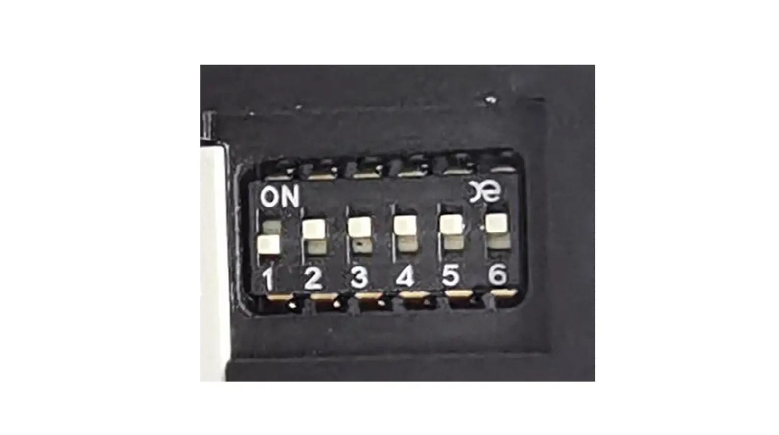
Factory test mode
Set the dial switch as below picture.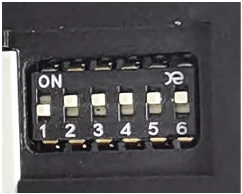
System Structure
Digital-in
Optical input can support a rate of 192Khz . Don’t support Dolby and DTS . only PCM 2.0.
Analog-in
Aux input max 1.25V rms input, standby mode by audio signal detector .
BT-in
ATS2819 moudle, Can support BT5.0 .
| Operating Frequency Band | 2.4GHz — 2.48GHz unlicensed ISM band |
| Bluetooth Specification | V2.1+EDR /V4.2 |
| Bluetooth Protocol | A2DP,AVRCP,HFP,SPP BAS,DIS,FMP,HRP,HRS,HTP,HTS,IAS.1_,LS |
| Output Power Class | Class 2 |
| Operating Voltage | Core: 1.2V, I0:3.1 V, BAT:3.3V-4.5V |
| Operating temperate range | -10°C — +70°C |
| External Interface | UART,SPI,TW1,12S,IR,SD Card,USB,DMIC |
DSP-functionality
The DSP(ADAU1761) – functionality consists of the following features:
- Volume control
- EQ
Amplification
The AMP(TPA3116) is class D – type, driving 4 ohms speakers.
User Interface
- output terminal (4 ohm loads can be connected and output 2X25W)
- AC in (100-240V~50/60Hz,80W )
- pair button (the remote control pair and reboot the BT)
- indication LED
- optical terminal
- Dial switch (set different EQ)
Bottom
- pair bottom : the remote control pair and factroy reset.
- Press and hold on till blink red: factroy reset.
indication LED
| LED | 1x RGB LED |
| Bluetooth mode | Blue |
| Optical | ORANGE |
| AUX | GREEN |
The buttons’ feature and led features.
Buttons:
| Button name | Button operation | Feature |
| pair button | Short Press | Enter the remote control pairing mode |
| Press hold on till blink red | factroy reset |
Led | Behavior | The meaning |
| RGB | Solid Red | Standby mode |
| Solid Green | AUX source | |
| Solid Orange | OPT source | |
| Solid Blue | BT source | |
| Blink Red fast | Factory data reset |
Performance specifications
Audio Specifications
Test conditions: BM240 coneccted with 4 ohm load .
Power AMP Section (Test mode)
| PARAMETER(aux in) | SPECS | |||
| Continuous Average Power | 4 ohms | 1kHz | ≥25W | |
| THD | 4 ohms | 25W | 1kHz | ≤1% |
| S/N | 25W | 1kHz | ≥80dB( A-weighted) | |
| Frequency Response | 20Hz – 20 kHz | +/-0.5dB | ||
| CHANNEL SEPARATION | ≥60db | |||
| Sensitivity | 800mv | |||
| PARAMETER(optical in) | SPECS | |||
| Continuous Average Power | 4 ohms | 1kHz | ≥25W | |
| THD | 4 ohms | 25W | 1kHz | ≤1% |
| S/N | 25W | 1kHz | ≥80dB( A-weighted) | |
| Frequency Response | 20Hz – 20 kHz | +/-0.5dB | ||
| CHANNEL SEPARATION | ≥60db | |||
| Sensitivity | 800mv | |||
| PARAMETER(BT in) | SPECS | |||
| Continuous Average Power | 4 ohms | 1kHz | ≥25W | |
| THD | 4 ohms | 25W | 1kHz | ≤1% |
FCC regulatory conformance
This device complies with Part 15 of the FCC Rules. Operation is Subject to the following two conditions:
- This device may not cause harmful interference.
- This device must accept any interference received, including interference that may cause undesired operation.
NOTE: This equipment has been tested and found to comply with the limits for a Class B digital device, pursuant to part 15 of the FCC Rules. These limits are designed to provide reasonable protection against harmful interference in a residential installation.
This equipment generates uses and can radiate radio frequency energy and, if not installed and used in accordance with the instructions, may cause harmful interference to radio communications. However, there is no guarantee that interference will not occur in a particular installation. If this equipment does cause harmful interference to radio or television reception, which can be determined by turning the equipment off and on, the user is encouraged to try to correct the interference by one or more of the following measures:
- Reorient or relocate the receiving antenna.
- Increase the separation between the equipment and receiver.
- Connect the equipment into an outlet on a circuit different from that to which the receiver is connected.
- Consult the dealer or an experienced radio/TV technician for help
NOTE: The manufacturer is not responsible for any radio or TV interference caused by unauthorized modifications to this equipment. Such modifications could void the user’s authority to operate the equipment.
RF Exposure
This equipment complies with FCC radiation exposure limits set forth for an uncontrolled environment.
IC regulatory conformance
This device complies with CAN ICES-003 (B)/NMB-003(B).
This device contains licence-exempt transmitter(s)/receiver(s) that comply with Innovation, Science and Economic Development Canada’s licence-exempt RSS(s). Operation is subject to the following two conditions:
- This device may not cause interference.
- This device must accept any interference, including interference that may cause undesired operation of the device.


