![]()
Installation
Instructions
Part # 12316510
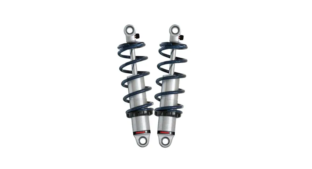
1965-1979 Ford F100 HQ Rear CoilOvers
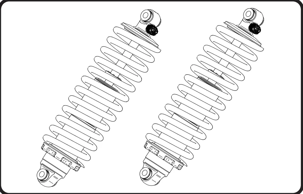
12316510 Rear HQ Coil-Overs for 4-Link
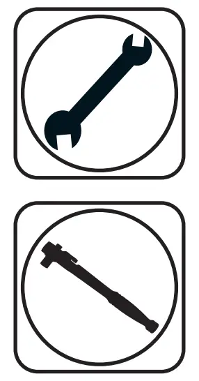
Recommended Tools
1965-1979 Ford F100 HQ Series Rear CoilOvers
Installation Instructions
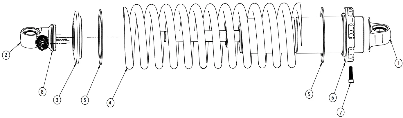
Major Components …..In the box
| Item # | Part # | Description | QTY |
| 1 | 982-10-805 | 5.2” Stroke HQ Series Shock | 2 |
| 2 | 815-05-022-KIT | Shock Eyelet | 2 |
| 3 | 803-00-109(kit) | Upper CoilSpring Retaining Plate (803-00-109 kit) | |
| 4 | 59120200 | Coilspring 12” 200lb | 2 |
| 5 | 70010828 | Delrin Spring Washer | 4 |
| 6 | 803-00-109(kit) | Lower Spring Adjuster Nut (803-00-109 kit) | 2 |
| 7 | 803-00-109(kit) | Adjuster Nut Locking Screw (803-00-109 kit) | 2 |
| 8 | 803-00-109(kit) | Retaining Ring (803-00-109 kit) | 2 |
| 90001994 | 5/8” ID Bearing (installed in shock and eyelet) | 4 | |
| 90001995 | Bearing Snap Ring (installed in shock and eyelet) | 8 | |
CoilOver Assembly…
First, using the supplied lower adjuster nut (80300-199) thread the nut onto the shock from the bottom side as seen in fi gure 1. Remove the plastic pellet that is in the split of the adjuster nut.
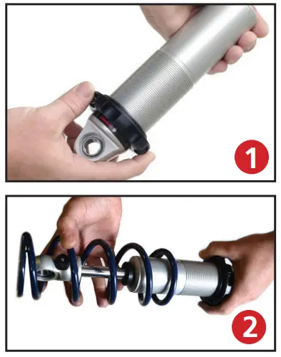
Next, install a delrin washer then coil spring over the top of the shock as seen in figure 2.
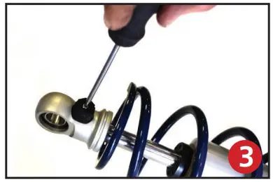
Before the upper spring mount can be installed screw the adjuster knob on the upper eye mount to the fi rmest setting (clockwise) as seen in fi gure 3. Then remove the Knob by holding it while removing the center screw.
Once the knob is removed slide a Delrin washer over the eyelet. Next, slide the upper spring mount (80300-199) over eyelet as seen in figure 4.
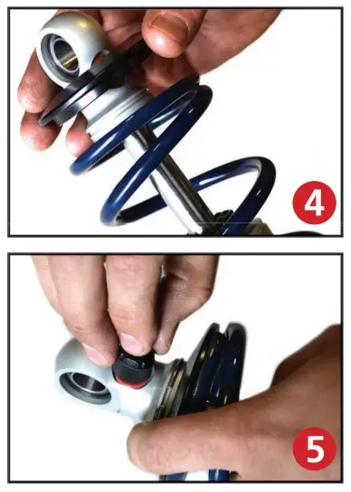
Install upper spring mount retainer clip (803-00-199) into the groove on the upper eyelet as seen in figure 5. Then, reinstall adjuster to complete assembly.
Install the locking screw in the adjuster nut before setting spring preload, but DO NOT tighten until the spring preload has been set.
NOTE: Remember to adjust the shock valving before driving, the shock is currently set to full stiff.
CoilSpring Adjustment
6. Preload the springs of the CoilOver 1” to start. Steps 6a – 6e will assist you with preloading the coilspring. You may need to adjust the amount of preload in the spring, but this will be determined after the vehicle has been sat on the ground.
6a. Verify the adjuster nut locking screw is installed in the adjuster nut, but not tight.
6b. Thread the spring adjuster nut up the shock body until it is snug against the spring. You should
NOT be able to move the spring up and down on the shock (0 preload). Verify the upper coilspring cap is seated correctly on the upper shock stud.
6c. Measure from the bottom of the adjuster nut to the flat of the shock. You may want to write the measurement down.
6d. Using a spanner wrench, thread the adjuster up the shock an additional 1” (from the measurement you took in step 2) to preload the spring.
6e. Lock the adjusting nut in place by tightening the adjuster nut locking screw.
7. Reinstall the rear wheels and tires and set the rear of the vehicle back on the ground.
8. After entire weight of vehicle is on the wheels, jounce the suspension and roll the car forward and backward to alleviate suspension bind. THIS IS NECESSARY BEFORE MEASURING RIDE HEIGHT.
9. If you determine you need to adjust the ride height of the rear suspension after getting the vehicle on the ground, Steps 9a – 9e will assist you in adjusting the ride height.
9a. Raise the vehicle and support it by the frame, allowing the suspension to hang freely. You do NOT need to remove the rear wheels.
9b. Loosen the locking screw in the adjuster nut, but do not remove the locking screw.
9c. Measure from the bottom of the adjuster nut to the flat of the shock. You may want to write the measurement down.
9d. Using a spanner wrench, thread the adjuster up or down the shock to obtain the correct ride height. One complete revolution of the adjuster nut is approximately 1/16” at the wheel. Threading the adjuster nut up the shock will raise the ride height, threading it down will lower the ride height.
9e. Lock the adjusting nut in place by tightening the adjuster nut locking screw.
10. After entire weight of vehicle is on the wheels, jounce the suspension and roll the vehicle forward and backward to alleviate suspension bind. THIS IS NECESSARY BEFORE MEASURING RIDE HEIGHT.
11. Recheck your ride height. If you need to readjust, repeat Steps 9-10.
Shock Adjustment 101- Single Adjustable
Rebound Adjustment:
How to adjust your new shocks.
The rebound adjustment knob is located on the top of the shock absorber protruding from the eyelet.
You must fi rst begin at the ZERO setting, then set the shock to a soft setting of 20.

-Begin with the shocks adjusted to the ZERO rebound position (full stiff). Do this by rotating the rebound adjuster knob clockwise until it stops.
-Now turn the rebound adjuster knob counter clock wise 20 clicks. This sets the shock at 20. (settings 21-24 are typically too soft for street use).
Take the vehicle for a test drive.

Take the vehicle for another test drive.

-if the vehicle is too soft increase the damping effect by rotating the rebound knob clock wise 3 additional clicks.
-If the vehicle is too stiff rotate the rebound adjustment knob counter clock wise 2 clicks and you are set!
Take the vehicle for another test drive and repeat the above steps until the ride quality is satisfactory.
Note: One end of the vehicle will likely reach the desired setting before the other end. If this happens stop adjusting the satisfi ed end and keep adjusting the unsatisfied end until the overall ride quality is satisfactory.
CoilOver Dimensions:
Center of bearing to Center of bearing:
Compressed: 11.23”
Ride Height: 14.50”
Extended: 16.43”
www.ridetech.com


