![]()
INSTALLATION INSTRUCTIONS

2013-2018 DODGE 3500 4WD
5” 4-LINK KIT W/ COILS
FTS23101/FTS23102/FTS23103 – 4-LINK KITS
FT23100i
K3089 5″ 4 Link System w/ Coil Springs & Performance Shocks
| FTS23085 | 5″ 4-LINK KIT W/ COILS | |
| 1 | FT44172 | DODGE PITMAN ARM |
| 1 | FT44236BK | TRACK BAR BRACKET |
| 1 | FT44298BK | LOWER SPRING PERCH (DRIVER) |
| 1 | FT44299BK | LOWER SPRING PERCH (PASSENGER) |
| 2 | FT44316BK | FRONT COIL SPRING |
| 1 | FT44300BK | 4 LINK BRACKET DRIVER |
| 1 | FT44301BK | 4 LINK BRACKET PASSENGER |
| 2 | FT44318BK | CROSSMEMBER BACK PLATE |
| 2 | FT44356BK | COIL RETAINER |
| FTS23100 | COMPONENT BOX 2 | |
| 1 | FT44518 | BUMP STOP MOUNT DRIVER |
| 1 | FT44519 | BUMP STOP MOUNT PASSENGER |
| 2 | FT44242BK | BUMPSTOP SPACER |
| 1 | FT44462 | HARDWARE KIT |
| 1 | FT44303BK | 4 LINK UPPER DRIVER |
| 1 | FT44304BK | 4 LINK UPPER PASSENGER |
| 1 | FT44305BK | 4 LINK LOWER DRIVER |
| 1 | FT44306BK | 4 LINK LOWER PASSENGER |
| FTS23101 | COMPONENT BOX 3 W/PERFORMANCE SHOCKS | |
| 2 | FTBK21 | 2.0” BLOCK |
| 4 | FT738U | UBOLTS |
| 1 | FT44367 | HARDWARE SUBASSEMBLY |
| 2 | FTS7343 | PERFORMANCE SHOCK (FRONT) |
| 2 | FTS7335 | PERFORMANCE SHOCK (REAR) |
| FTS23102 | COMPONENT BOX 3 W/STEALTH SHOCKS | |
| 2 | FTBK21 | 2.0 BLOCK |
| 4 | FT738U | UBOLTS |
| 1 | FT44367 | HARDWARE SUBASSEMBLY |
| 2 | FTS6343 | STEALTH MONOTUBE (FRONT) |
| 2 | FTS6335 | STEALTH MONOTUBE (REAR) |
| FTS23089 | COMPONENT BOX 3 W/DIRT LOGIC SS SHOCKS | |
| 2 | FTBK21 | 2.0 BLOCK |
| 4 | FT738U | UBOLTS |
| 1 | FT44368 | HARDWARE SUBASSEMBLY |
| 2 | FT801032 | 2.25 DIRT LOGIC SS RESI (FRONT) |
| 2 | FT810362 | 2.25 DIRT LOGIC SS NON RESI (REAR) |
| FT44462 – HARDWARE KIT | LOCATION | |
| FT44369 | ||
| BAG 1 | ||
| 1 | M18-2.5 X 90MM HEX BOLT | TRACK BAR DROP BRACKET |
| 2 | M18 WASHERS | |
| 1 | NUT C-LOCK 18MM G10.9 ZINC | |
| 2 | 1/2-13 X 1-1/2 HEX BOLT G8 ZINC | TRACK BAR BRACKET |
| 4 | 1/2” WASHERS | |
| 2 | 1/2 -13 C-LOCK NUT ZINC | |
| 2 | 1/2-13 X 4” HEX BOLT G8 | COIL RETAINER |
| 4 | 1/2 SAE WASHER G8 ZINC | |
| 2 | 1/2 -13 C-LOCK NUT ZINC | |
| BAG 2 | ||
| 4 | 1/4 SAE WASHER | |
| 2 | 1/4-20 C-LOCK NUTS | BUMP STOP |
| 2 | 1/4-20 X 1 HEX BOLT | |
| 4 | 1/2-13 1-1/4 HEX BOLT ZINC | |
| 8 | 1/2 SAE WASHER ZINC | |
| 2 | 5/16-18 X 2-1/2 HEX BOLT ZINC | |
| 10 | 5/16 SAE WASHER G8 ZINC | |
| 4 | 5/16-18 C-LOCK NUT ZINC | |
| 4 | 5/16-18 X 1-1/2 HEX BOLT | |
| BAG 3 | ||
| 4 | 7/16-14 X 1-1/4 HEX BOLT ZINC | REAR BUMP STOP |
| 8 | 7/16 SAE WASHER G8 ZINC | |
| 4 | 7/16-14 C-LOCK NUT ZINC | |
| 8 | 9/16” SAE WASHER | UBOLTS |
| 8 | 9/16-18 NYLOCK NUT | |
| BAG 4 | ||
| 2 | 7/16-14 X 1-1/4 HEX BOLT G8 ZC | |
| 2 | 7/16 SAE WASHER G8 ZINC | |
| 2 | 7/16 LOCK WASHER | |
| 4 | 1/2-13 X 1-1/2 HEX BOLT G8 ZNC | |
| 4 | 1/2-13 C-LOCK NUT G8 | |
| 6 | 1/2 SAE WASHER G8 ZINC | |
| 10 | 5/8-11 X 1-3/4 HEX BOLT | |
| 20 | 5/8 SAE WASHER | |
| 10 | 5/8-11 C-LOCK NUT | |
| 2 | 3/4-10 X 1-1/4 HEX BOLT | |
| 2 | 3/4-10 X 2” HEX BOLT | |
| 20 | 3/4 SAE WASHER | |
| 4 | 3/4-10 X 5” HEX BOLT | |
| 8 | 3/4-10 C-LOCK NUT |
| FT44367 | HARDWARE SUBASSEMBLY | |
| 2 | FT44317 | LOWER SPRING PERCH NUT TAB |
| 2 | FT44135 | BUMP STOP MOUNT TAB |
| 2 | FT44245 | BRAKE LINE EXT |
| 1 | FT44246 | TRACK BAR SUPPORT SPACER |
| 2 | FT44258 | 1/4 NUT TAB |
| 1 | FT50184 | TRAC BAR SUPPORT NUT TAB |
| 1 | FT23100i | INSTRUCTIONS |
| 1 | FT44359 | COIL RETAINER WASHER |
| 1 | FT44239 | WASHER 4.250 X .510 X .250 |
| 4 | FT44302 | MISALIGNMENT |
| 4 | FT103 | MISALIGNMENT SPACER CLEAR ZINC |
| 4 | FT404739 | SLEEVE OD 0.62, ID 12MM, L1.48 |
| 2 | FT44324 | NUT TAB |
| 1 | FT44223 | NUT TAB |
| 1 | FT30182 | NUT TAB |
| 1 | FTAS16 | DRIVER WARNING DECAL |
| 1 | FTAS12 | STICKER FT BLUE 10X4 |
| 1 | FIREGUARD | REGISTRATION CARD |
| FT44368 | HARDWARE SUBASSEMBLY | |
| 2 | FTSP01029 | HARDWARE PACK STEM BUSHING |
| 2 | FT86021 | HARDWARE & BUSHING KIT 21 |
| 4 | FT83076 | 1.5/1.75-2.25/2.5 RESI URETHANE |
| 4 | FT89016 | #64 HOSE CLAMP |
| 2 | FT44317 | LOWER SPRING PERCH NUT TAB |
| 2 | FT44135 | BUMP STOP MOUNT TAB |
| 2 | FT44245 | BRAKE LINE EXT |
| 1 | FT44246 | TRACK BAR SUPPORT SPACER |
| 2 | FT44258 | 1/4 NUT TAB |
| 1 | FT50184 | TRAC BAR SUPPORT NUT TAB |
| 1 | FTAS16 | DRIVER WARNING DECAL |
| 1 | FTAS12 | STICKER FT BLUE 10X4 |
| 1 | FTREGCARD | REGISTRATION CARD |
| 1 | FT23100i | INSTRUCTIONS |
| 1 | FT44359 | COIL RETAINER WASHER |
| 1 | FT44239 | WASHER 4.250 X .510 X .250 |
| 4 | FT44302 | MISALIGNMENT |
| 4 | FT103 | MISALIGNMENT SPACER CLEAR ZINC |
| 1 | FT30182 | NUT TAB |
| 2 | FT44324 | NUT TAB |
| 2 | FT86008 | HARDWARE & BUSHING KIT 8 |
| 1 | FT44223 | NUT TAB |
TOOL LIST
Required Tools (Not Included)
– Basic Hand Tools
– Floor Jack
– Jack Stands
– Assorted Metric and S.A.E sockets, and Allen wrenches
– Torque Wrench
– Die Grinder w/ Cutoff Wheel or Sawzall
PRE-INSTALLATION NOTES
For technical assistance call: 909-597-7800 or e-mail: [email protected]
Read this before you begin installation-
Check all parts to the parts list above before beginning installation. If any parts are missing contact Fabtech at 909-597-7800 and a replacement part will be sent to you immediately.
This suspension and shocks has been designed to be installed on a stock vehicle.
Read all instructions thoroughly from start to finish before beginning the installation. If these instructions are not properly followed severe frame, driveline, and/or suspension damage may occur. Check your local city and state laws prior to the installation of this system for legality. Do not install if not legal in your area. Prior to the installation of this suspension system perform a front-end alignment and record. Do not install this system if the vehicle alignment is not within factory specifications. Check for frame and suspension damage prior to installation. The installation of this suspension system should be performed by two professional mechanics.
This suspension must be installed with Fabtech shock absorbers. Use the provided thread-locking compound on all hardware.
WARNING- Installation of this system will alter the center of gravity of the vehicle and may increase rollover as compared to stock. Vehicles that receive oversized tires should check ball joints, uni balls, tie rod ends, pitman’s arm, and idler arm every 2500- 5000 miles for wear and replacement as needed. Verify differential fluid is at the manufactures recommended level prior to kit installation. Installation of the kit will reposition the differential and the fill plug hole may be in a different position. (For example, if the manufacturer recommends 3 quarts of fluid, make sure the diff has 3 quarts of fluid). Check your specific manual for the correct amount of fluid.
FOOTNOTES-
Will not fit gas motors.
– Does not fit power wagon models.
– Does not fit dually models.
– For vehicles equipped with automatic transmissions only
RECOMMENDED TIRE/WHEEL SIZES –
– 37×12.50/R17 tire w/ 17×9 wheels w/ 5” BS w/ minor trimming
– 37×12.50/R18 tire w/ 18×9 wheels w/ 5” BS w/ minor trimming
– 37×13.50/R20 tire w/ 20×9.5 wheels w/ 5” BS w/ minor trimming
– 37×13.50/R22 tire w/ 22×9.5 wheels w/ 5” BS w/ minor trimming
INSTRUCTIONS
FRONT SUSPENSION
- Disconnect the negative terminal on the battery. Jack up the front end of the truck and support the frame rails with jack stands. NEVER WORK UNDER AN UNSUPPORTED VEHICLE! Remove the front tires.
- DRIVER SIDE ONLY – Starting on the driver side, remove the driver-side fender liner.
- Remove the factory shock and discard. Retain factory lower hardware.
- Disconnect factory sway bar links.
- Remove the factory coil spring and rubber isolator. Retain these parts for later use.
- Remove the factory pitman arm and discard. Keep hardware.
- Locate the new FT44172 Fabtech pitman arm and install it. Do not reconnect the factory drag link at this time. Reinstall the factory lock washer plus thread locker. Torque to 220ft-lbs.
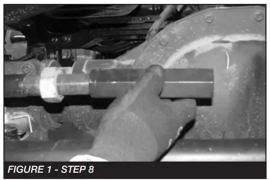
- Unthread the factory drag link at the adjuster sleeve and remove the adjuster sleeve. SEE FIGURE 1

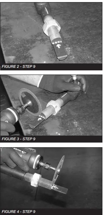
- Using a die grinder remove the flat nonthreaded section from both ends of the drag link. This will allow you to rotate the drag link and line it up with the pitman arm.
SEE FIGURES 2-4
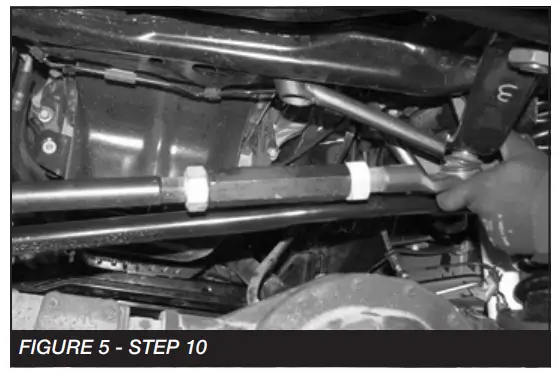
- Reassemble the drag link and connect it to the new pitman arm. SEE FIGURE 5

- Torque the drag link to 83 ft-lbs.
- Remove the track bar from the frame side of the vehicle.
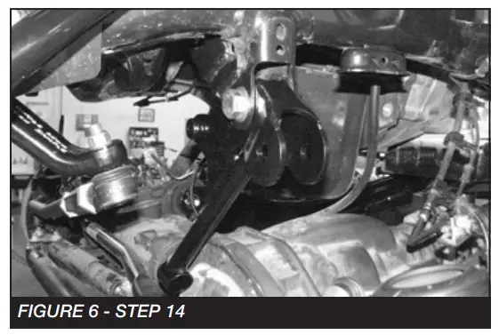
- Locate the FT44236BK track bar bracket and M18–2.5 x 90mm bolt.
- Slide the track bar bracket into the factory mount and insert the M18 bolt into the factory pivot hole. SEE FIGURE 6

- Rotate the bracket up until the end of the bracket is flush with the cross member under the motor.
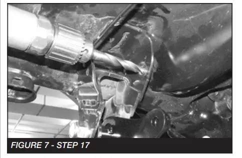
- Using the Fabtech bracket as a guide, mark the factory mount for the upper driver-side mounting hole.
- Swing the bracket back out of the way. Using a ½“ drill bit, drill out the marked hole. SEE FIGURE 7

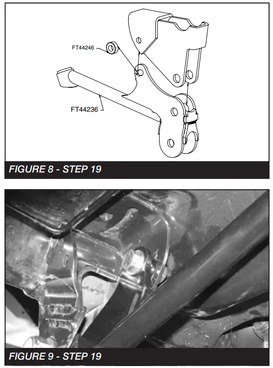
- Locate one FT44246 sleeve and two 1/2”-13 x 1-1/2” bolts, nuts, and washers.
- Rotate the track bar bracket back into place and bolt together using a 1/2”-13 x 1-1/2” bolt and the sleeve. SEE FIGURES 8-9

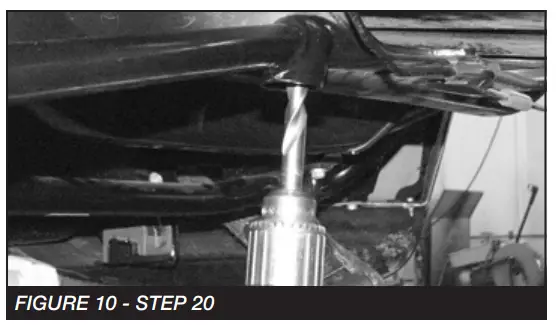
- Using the Fabtech bracket as a guide, drill a 1/2’’ hole in the cross member under the motor. Next, mount using 1/2”-13×1.5” and washer. SEE FIGURE 10

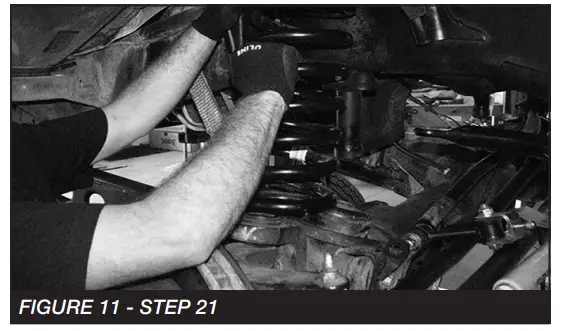
- Remove the factory coil springs and lower rubber isolators. SEE FIGURE 11

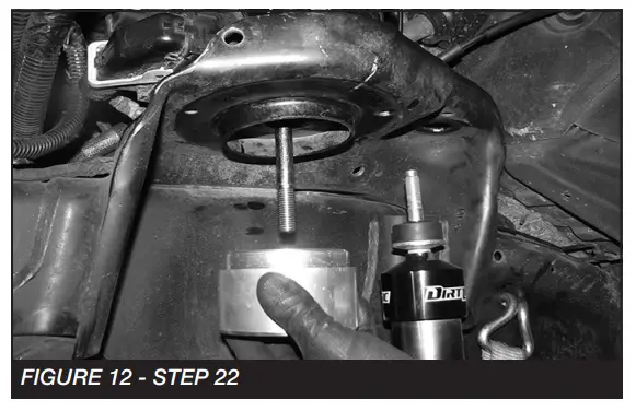
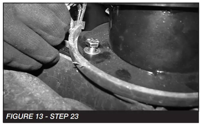
- (DRIVER SIDE) Locate FT44356BK ( Coil Retainer), FT44359 (Washer), 1/2”-13 X 4” Bolt, nut and washer. (Driver side) Remove the bolts attaching the ABS module to the spring perch and install the 1/2” bolt and FT44359. Install the FT44356BK (Retainer) and 1/2” washer and nut. Torque to 100 ft-lbs. SEE FIGURE 12 (PASSENGER SIDE) Repeat the same process using FT44239 (Washer). SEE FIGURE 13
NOTE: IF INSTALLING DUAL SHOCKS DO SO NOW WITH THE INSTRUCTIONS PROVIDED

- Locate FT44298BK (lower spring perch spacer), FT44317 (lower spring perch nut tab) and 5/16” hardware. Install the new spring spacer by lining up the existing rear hole.
Use the 5/16” hardware and FT44317 nut tab. SEE FIGURE 13
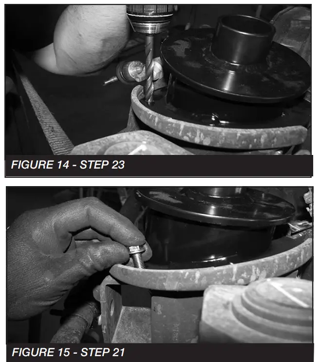
- Using the existing spacer hole as a guide, drill through the factory spring perch using an 11/32” drill bit and install the 5/16” hardware to 29 ft-lbs. SEE FIGURES 14-15

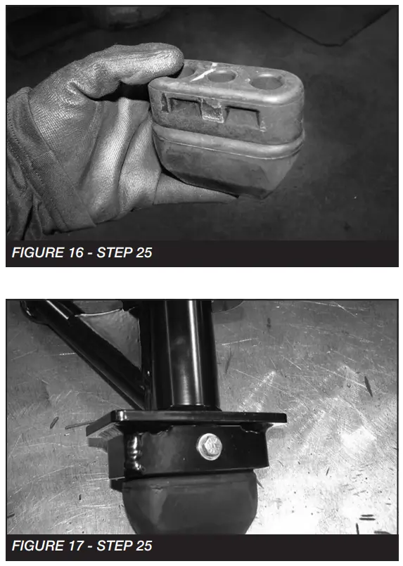
- Remove and save the factory rubber bump stop. SEE FIGURE 16. Insert the factory rubber bump stop into the new Fabtech bump stop bracket (FT44518). Using a 1/4” drill, drill a hole through the factory rubber bump and stop using the new bracket as a guide. Then install the supplied 1/4” X 2-1/2” hardware. Torque to 14 ft-lbs. SEE FIGURE 17

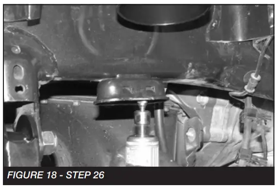
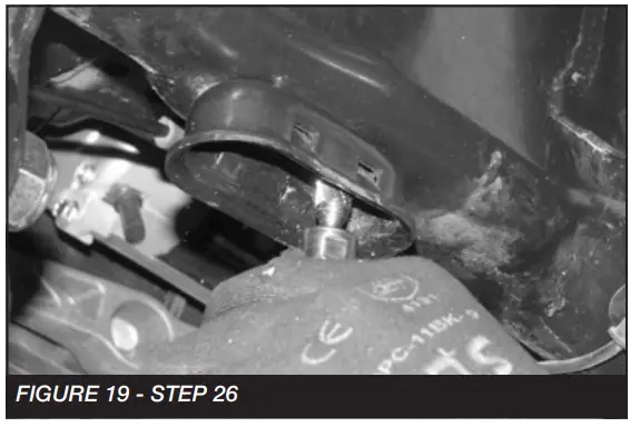
- Using a die grinder, grind out the stamped-in tabs on the inside of the bump stop housing. SEE FIGURES 18-19


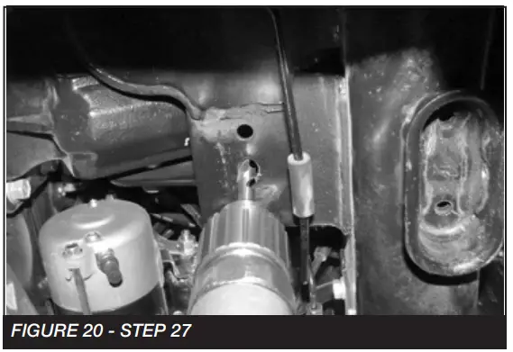
- Using a 1/2” drill bit, drill out the hole in the factory cross member inline with the factory bump stop mount. SEE FIGURE 20

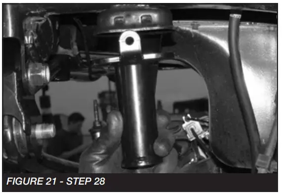
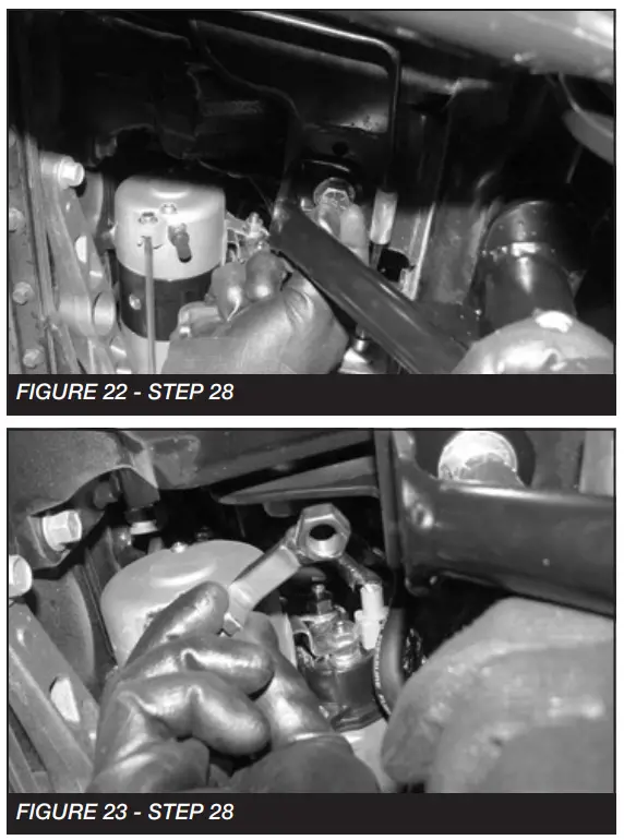
- Slide the bump stop into the factory bump stop mount. Using a 1/2”-13 x 1-1/4” bolt and the FT44135 (nut tab), bolt the bump stop to the cross member. Torque the 1/2” bolt to 90 ft-lbs. SEE FIGURES 21-23


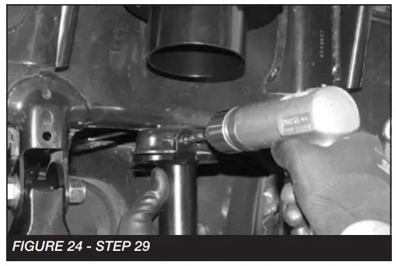
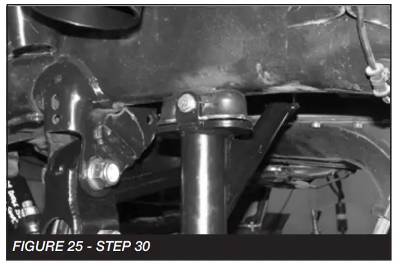
- Using the outer tab on the bump stop as a drill guide, drill a 5/16” hole all the way through the factory bump stop mount. SEE FIGURE 24

- Locate a 1/4 x 2-1/2” bolt, nut, and washers. Using this bolt, secure the bump stop to the factory bump stop mount and torque to 29 ft-lbs. SEE FIGURE 25

- Repeat steps 2-30 on the passenger side.
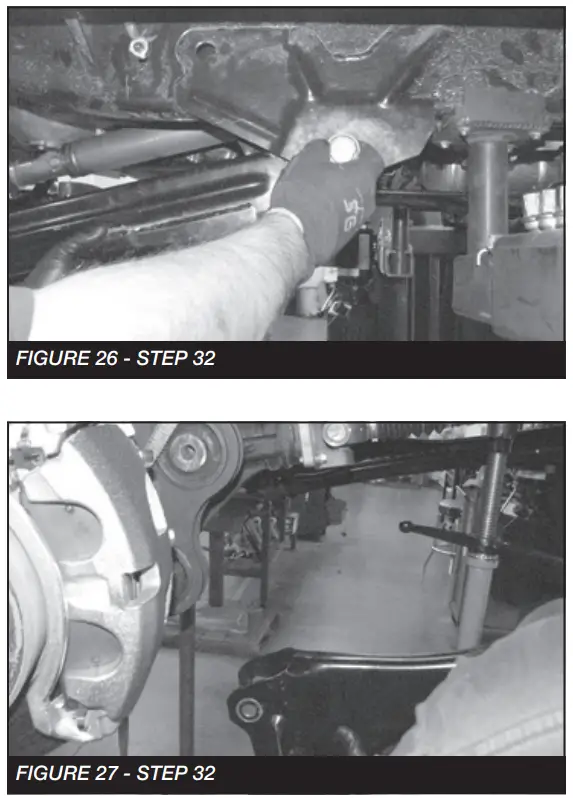
- Secure the front diff. Remove the factory driver and passenger side Radius arm. Retain Hardware. SEE FIGURES 26-27
 NOTE: SUPPORT THE TRANSFER CASE AT THIS TIME
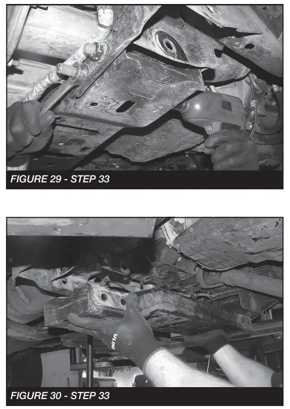
 - Remove the factory cross member and a skid plate that is mounted between the factory radius arm pockets. Retain Hardware. SEE FIGURES 28-30

 • NOTE: Trim a 2” radius off the inner front radius arm bracket. SEE FIGURE BELOW
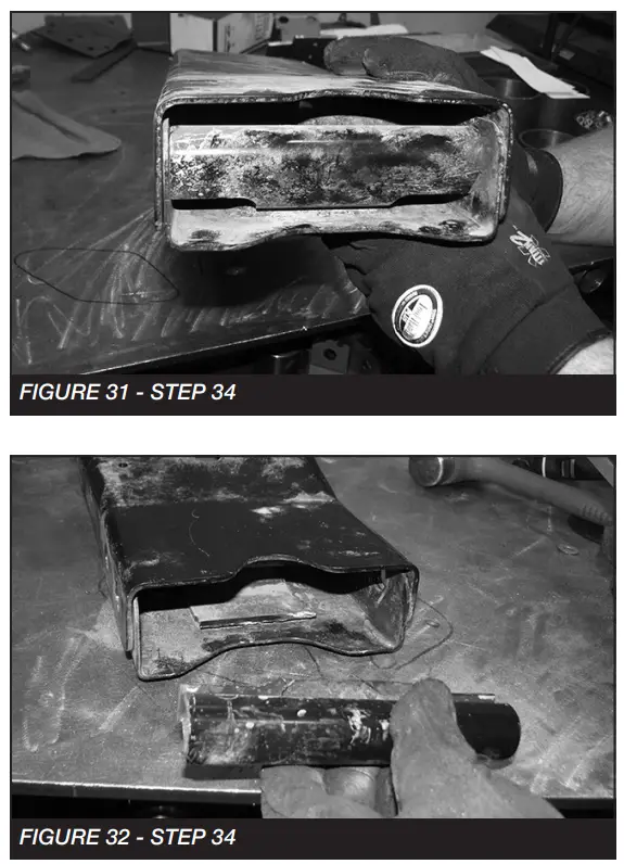
- Once the cross member is out. The inner support sleeve will need to be cut out on both sides. SEE FIGURES 3132

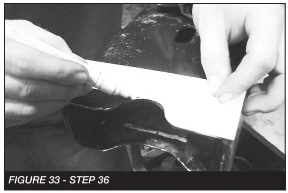
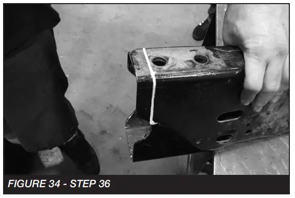
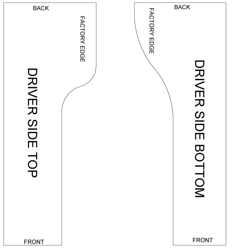
- Locate and cut out the 4-Link templates on the last pages.
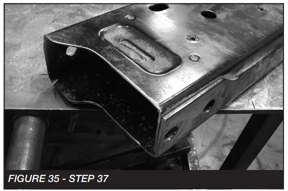
- Starting on the driver-side top of the cross member. Place the correct template on the cross member so the edge of the template lines up to the factory edge on the cross member. Mark for cutting. Do the same with the Driver side bottom. Follow the mark around the side and connect with the mark on the top. SEE FIGURES 33-34


- Carefully cut the cross member where you made the marks. Sand to a smooth edge. FIGURE 35 shows what the driver’s side should look like when complete.

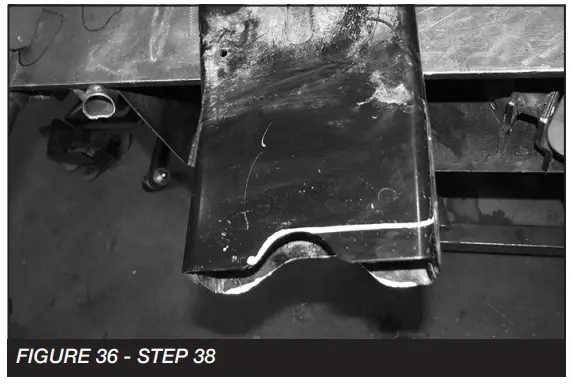
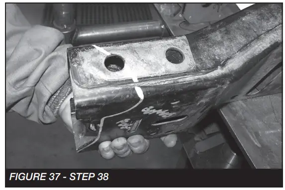
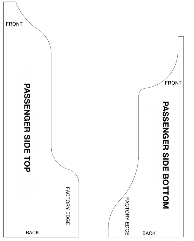
- Moving to the passenger side of the cross-member. Place the cutout templates on the cross member and mark them for cutting. SEE FIGURES 36-37

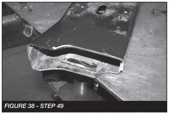
- Carefully cut the cross member where you made the marks. Sand to a smooth edge. FIGURE 38 shows what the passenger side should look like when complete. SEE FIGURE 38

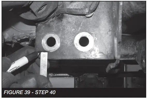
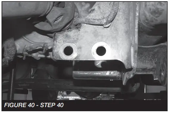
- Locate the factory driver-side cross-member frame mount. On the front side only trim 1/2” off the bottom as shown.SEE FIGURES 39-40


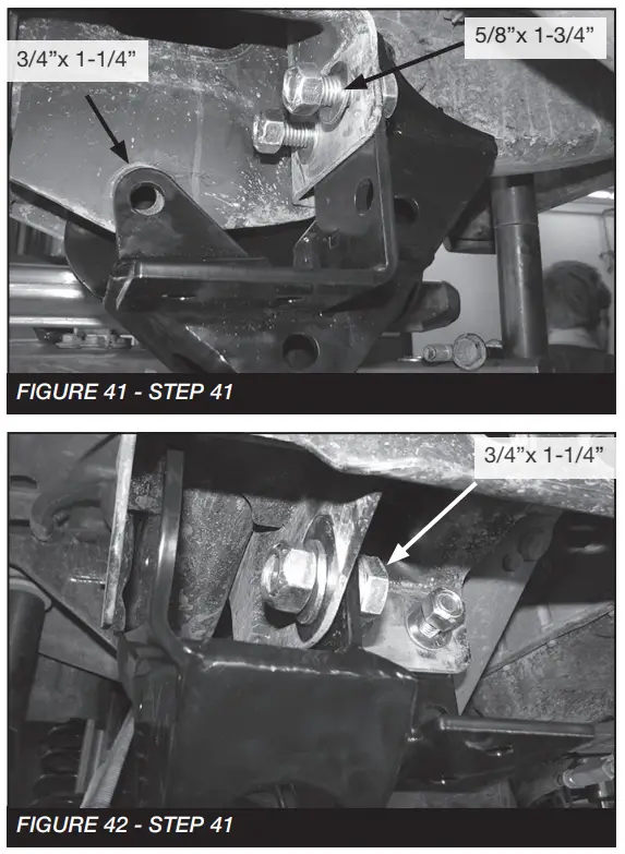
- Locate FT44300BK (4-Link Driver Bracket), starting on the driver’s side. Install the bracket as shown below using the 5/8”x 1-3/4” hardware and 3/4”x 1-1/4” hardware from Bag 5 in the hardware kit. Leave loose. SEE FIGURES 41-42

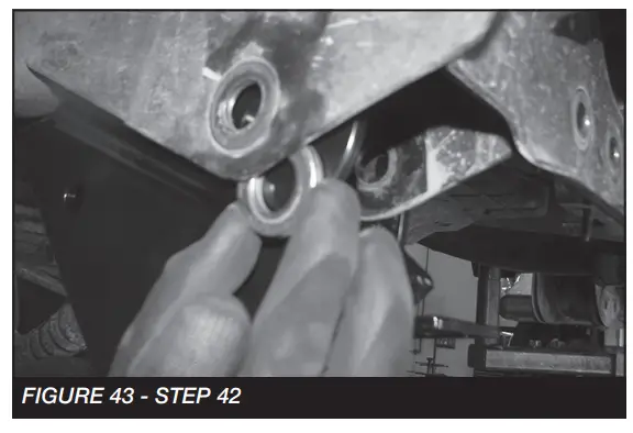
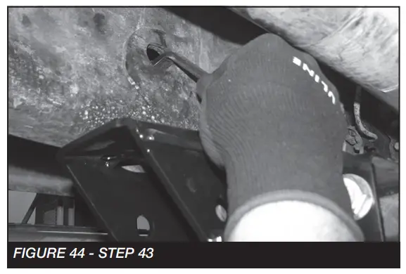
- From Bag 5, Locate the 3/4”-10 X 2” Bolt, 4 washers, and nut.
NOTE: When installing the 3/4” bolt insert 2 washers between the factory bracket and the new Fabtech 4-link bracket. Leave loose. SEE FIGURE 43
- Locate FT44324 (Nut Tab) and 7/16” X 1-3/4” bolts and washers. Insert the nut tab through the hole on the frame and install the 7/16” bolt and washers. Torque to 83 ft-lbs. Torque the hardware installed on the previous steps to the below specifications. SEE FIGURES 44
• 5/8”- 254 ft-lbs
• 3/4”- 450 ft-lbs • REPEAT STEPS 42-44 ON PASSENGER SIDE
 - Locate FT44318BK (Crossmember Back Plate) and 5/8” Hardware. Install the factory cross member like shown in FIGURES 45-47 using the FT44318BK bracket, 5/8”
hardware and 1 of the factory bolts. Torque to 254 ft-lbs.
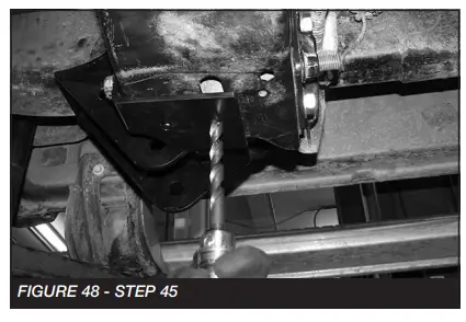
- Using a 17/32” drill bit. Drill 4 total holes, 2 on the driver side and 2 on the passenger side through the cross member using the holes in the brackets as guides. SEE FIGURE 48

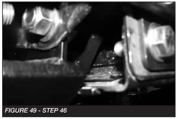
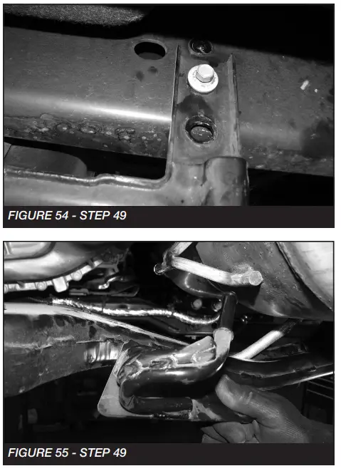
- Starting with the driver side locate FT44223 (nut tab) (2) 1/2-13 X 1-1/2”, washers and (1) 1/2” C-lock nut.
NOTE: The nut tab will be used towards the front of the vehicle. Torque to 90 ft-lbs. SEE FIGURE 49
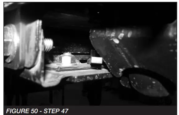
- Next for the passenger side locate FT30182 (nut tab) (2) 1/2-13 X 1-1/2”, washers and (1) 1/2” C-lock nut. Toque to 90 ft-lbs. SEE FIGURE 50

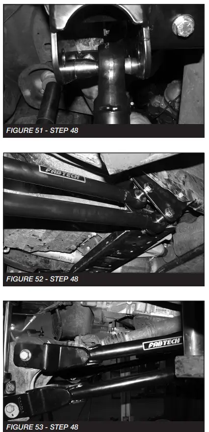
- Locate and install FT44302 (Outer misalignment spacer) and FT103 (Inner misalignment spacer) onto the new 4-link arms. Install the new arms with the provided 3/4” x
5” bolts and hardware. Re-use the factory hardware for the axle side. Torque to 317 ft-lbs. SEE FIGURES 51-53
- Locate the factory rear cross member. Remove and discard the exhaust rubber isolator and bracket from the cross member. Next, with assistance remove the 6 bolts that hold the cross member on the frame and lower the cross member to the bottom factory holes.
NOTE: Only 3 bolts will be used to re-attach the cross member. SEE FIGURE 54-55
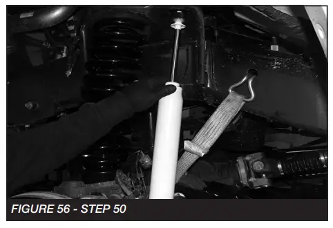
- Locate and install the new coil spring (FT44316BK) using the factory coil spring isolator. SEE FIGURE 56
 • REPEAT STEP 50 ON THE PASSENGER SIDE
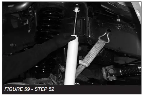
 - Locate the FT44245 Brake line extension, FT44258 nut tab, and two 1/4”-20 x 1” bolts. Attach the brake line extension to the axle using one bolt and the nut tab. Attach the factory brake line bracket to the Fabtech extension. Torque to 10 ft-lbs. Repeat this step on the passenger side. SEE FIGURES 57-58

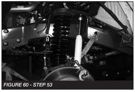
- Locate FTS7343 (Performance), FTS6343 (Stealth) or FTS811031 (Dirt Logic shock) and install into the factory shock mounts. Torque the upper mount to 14 ft-lbs and the lower 37 ft-lbs. SEE FIGURES 59

- Reconnect the factory sway bar. Torque to 29 ft-lbs. SEE FIGURE 60
 • REAR SUSPENSION
 - Jack up the rear end of the vehicle and support the frame rails with jack stands and remove wheels and tires. Remove the rear driver and passenger inner fender liners. SEE FIGURE 61

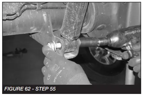
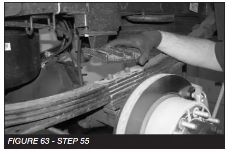
- Supporting the rear differential, remove and discard the rear shocks and u-bolts. Lower the axle down slowly. Use care not to over-extend the brake hoses. SEE FIGURES 62-63


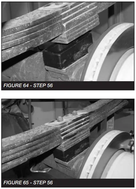
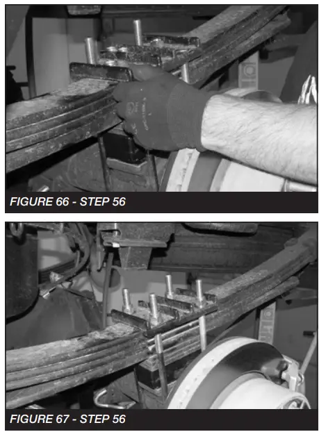
- Locate the supplied 2” blocks FTBK21, FT738U u-bolts, and 9/16” hardware. Install the block onto the axle with the small end of the taper to the front of the truck. Using the supplied u-bolts, nuts and washers, align the axle, lift block, and springs, and torque to u-bolts to 129 ft-lbs. SEE FIGURES 64-67


- Install new Fabtech Performance shocks (FTS7335), Stealth (FTS6335) or Dirt Logic 2.25” (FTS810362) with the factory hardware and torque upper and lower bolts to 29 ft-lbs.
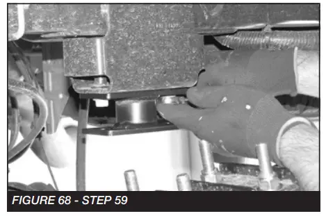
- Locate the FT44242BK bump stop extension. Remove driver and passenger factory bump stop. Retain Hardware.
- Install the bump stop extension to the factory mount using the factory hardware and torque to 65 ft-lbs. SEE FIGURE 68

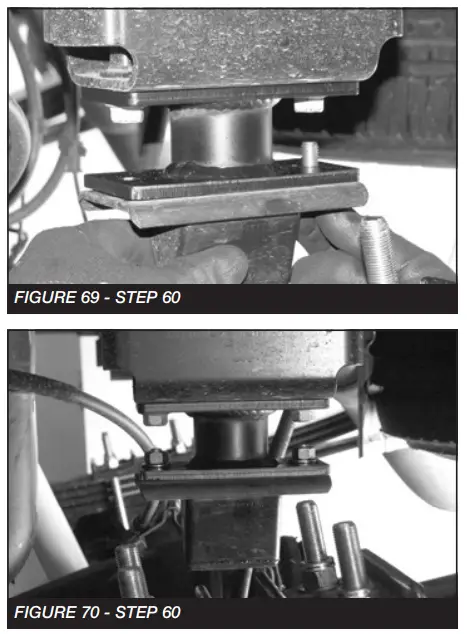
- Using a 7/16”-14 x 1-1/4” bolt, nuts, and washers, mount the factory bump stop to the extension. Torque to 59 ft-lbs. SEE FIGURES 69-70

- Re-Install both front and rear inner fender liners.
- Install tires and wheels and torque lug nuts to the wheel manufacturer’s specifications. Turn the front tires left to right and check for appropriate tire clearance. Note – Some
oversized tires may require trimming of the front bumper & valance. - Check front-end alignment and set it to factory specifications. Readjust headlights. Recheck all bolts for proper torque.
- Recheck brake hoses, ABS wires, and suspension parts for proper tire clearance while turning tires fully left to right.
- Install Driver Warning Decal. Complete the product registration card and mail it to Fabtech in order to receive the future safety and technical bulletins on this suspension.
 NOTE: SUPPORT THE TRANSFER CASE AT THIS TIME
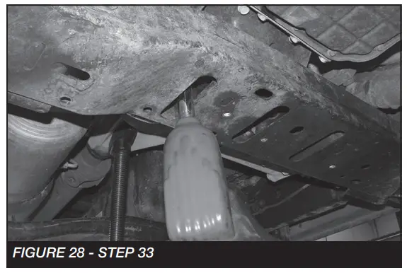
 • NOTE: Trim a 2” radius off the inner front radius arm bracket. SEE FIGURE BELOW
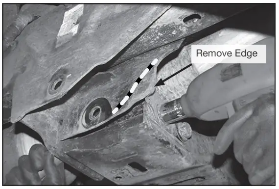
 • REPEAT STEPS 42-44 ON PASSENGER SIDE
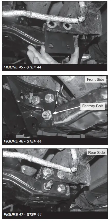
 • REPEAT STEP 50 ON THE PASSENGER SIDE
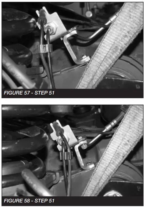
 • REAR SUSPENSION
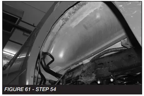
Vehicles that will receive oversized tires should check ball joints, uni balls, and all steering components every 2500-5000 miles for wear and replacement as required.
RE-TORQUE ALL NUTS, BOLTS, AND LUGS AFTER 50 MILES AND PERIODICALLY THEREAFTER.
For technical assistance call: 909-597-7800
Product Warranty and Warnings
Fabtech provides a Limited Lifetime Warranty to the original retail purchaser who owns the vehicle, on which the product was originally installed, for defects in workmanship and materials. The Limited Lifetime Warranty excludes the following Fabtech items; bushings, bump stops, ball joints, tie rod ends, limiting straps, cross shafts, Heim joints, and driveshafts. These parts are subject to wear and are not considered defective when worn. They are warranted for 60 days from the date of purchase for defects in workmanship. Dirt Logic and Performance Coilover take-apart shocks are considered serviceable shocks with a one-year warranty on leakage only. Service seal kits are available separately for future maintenance. All other shocks are covered under our Limited Lifetime Warranty. Fabtech does not warrant any product for finish, alterations, modifications, and/or installation contrary to Fabtech’s instructions. Alterations to the finish of the parts including but not limited to painting, powder coating, plating, and/or welding will void all warranties. Some finish damage may occur to parts during shipping, which is considered normal and is not covered under warranty. Fabtech products are not designed nor intended to be installed on vehicles used in race applications or for racing purposes or for similar activities. (A “RACE” is defined as any contest between two or more vehicles, or any contest of one or more vehicles against the clock, whether or not such contest is for a prize). This warranty does not include coverage for police or taxi vehicles, race vehicles, or vehicles used for government or commercial purposes. Also excluded from this warranty are sales outside of the United States of America. Installation of most suspension products will raise the center of gravity of the vehicle and will cause the vehicle to handle differently than stock. It may increase the vehicle’s susceptibility to a rollover, on-road and off-road, at all speeds. Extreme care should be taken to operate the vehicle safely at all times to prevent rollover or loss of control resulting in serious injury or death. Fabtech front-end Desert Guards may impair the deployment or operation of vehicles equipped with supplemental restraining systems/air bag systems and should not be installed if the vehicle is equipped as so. Fabtech makes every effort to ensure the suspension product compatibility with all vehicles listed on the website, but due to unknown auto manufacturer’s production changes and/or inconstancies by the auto manufacturer, Fabtech cannot be responsible for 100% compatibility, including the fitment of tire and wheel sizes listed. The Tire and Wheel sizes listed on Fabtech’s website are only a guideline for street driving with noted fender trimming. Fabtech is not responsible for damages to the vehicle’s body or tires. Fabtech is not responsible for premature wear of factory components due to the installation of oversized tires and wheels. Fabtech’s obligation under this warranty is limited to the repair or replacement, at the Fabtech option, of the defective product only. All costs of removal, installation or re-installation, freight charges, and incidental or consequential damages are expressly excluded from this warranty. Fabtech is not responsible for damages and/or warranty of other vehicle parts related or nonrelated to the installed Fabtech product. This warranty is expressly in lieu of all other warranties expressed or implied. This warranty shall not apply to any product that has been subject to accident, negligence, alteration, abuse, or misuse as determined by Fabtech. Fabtech suspension components must be installed as a complete system including shocks as shown on our website. All warranties will become void if Fabtech parts are combined and/or substituted with other aftermarket suspension products. Combination and/or substitution of other aftermarket suspension parts may cause premature wear and/or product failure resulting in an accident causing injury or death. Fabtech does not warrant products not manufactured by Fabtech. Depending on the condition of the factory suspension components retained after the installation of a Fabtech suspension, not all vehicles may have the same ride stance front to rear as described in the website. The blue color of suspension components shown in all Fabtech photographs is for display purposes only. The majority of all Fabtech components will be black specifically where noted with part numbers ending in BK. Installation of Fabtech products may void the vehicle’s factory warranty; it is the consumer’s responsibility to check with their local vehicle’s dealer for warranty disposition before the installation of the product. Some state laws may prohibit the modification of suspension to a vehicle in whole or in part. It is the responsibility of the installer and consumer to consult local laws prior to the installation of any Fabtech suspension product to comply with such written laws. It is the responsibility of the distributor and/or the retailer to review all warranties and warnings of Fabtech products with the consumer prior to purchase. Fabtech reserves the right to super cede, discontinue, or change the design, finish, part number, and/or application of parts when deemed necessary without written notice. Fabtech is not responsible for misprints or typographical errors within the website or price sheet. For the most recent Product Warranty and Warnings visit our website www.fabtechmotorsports.com
4-LINK TEMPLATE
PRINT AT 100% – DO NOT SCALE TO PAGE
4-LINK TEMPLATE
PRINT AT 100% – DO NOT SCALE TO PAGE
 Fabtech Motorsports
| 4331 Eucalyptus Ave. Chino, CA 91710
Tech Line: 909-597-7800
| Fax: 909-597-7185
| Web: www.fabtechmotorsports.com


