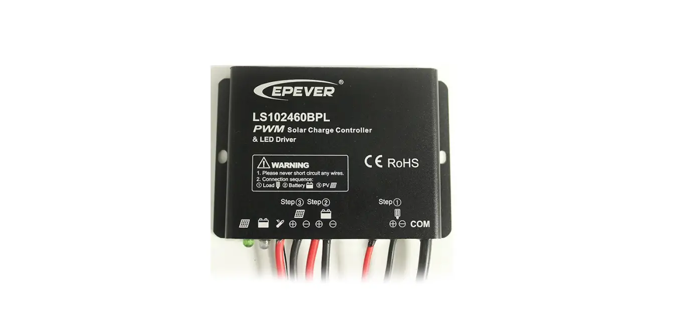
EPEVER LS-LPLI Series Charge Controller & LED Driver
Overview
The LS LPLI series controller combines the solar charge controller and LED constant current driver in one unit. It is ideal for solar LED lighting, especially for the LED lamp application, which requires dimmer function. The advanced pulse width modulation charging methods enables system charging and discharging management to obtain the most radical optimization. Make the system cost reduce and increase system flexibility.
Features:
- Apply to lead-acid battery and lithium battery
- Lithium battery self-activating function
- Lithium battery low-temperature protection function
- Intelligent power mode with 365-day lighting control technology
- Load power reduction automatically
- Load power limitation function
- Maximum output efficiency of 96%
- Digital precision constant current control and the control accuracy are less than±2%
- Discharging power calculation and real-time energy statistics recording function
- Configurable multiple load control modes, LED rated current, and the current percentage
- Load test function for detecting the system
- Extensive electronic protections
- Without any button, parameter setting via RC-10 and FC-01 with IR function.
- Fully encapsulated PCB, IP68 protection
- Aluminum housing for better cooling
Product Features
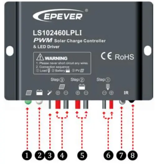
- Charging Status LED indicator
- Battery Status LED indicato
- Temperature Sensor ※
- PV Positive and Negative Wires
- Battery Positive and Negative Wires
- Load Positive and Negative Wires
- Infrared Receiver Module
- Infrared LED
If the temperature sensor connection is short-circuited or open-circuit, the controller charges or discharges the battery at 25℃ and no temperature compensation.
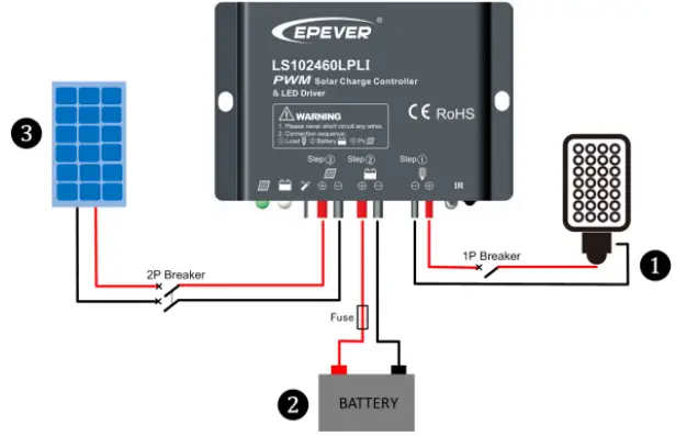
Wiring
Reference for Serial connection of LED
Connection Order
- Connect components to the charge controller in the sequence, as shown in Figure 2 Wiring, and pay much attention to the “+” and “-.” Please don’t insert the fuse or turn on the breaker during the installation. When disconnecting the system, reverse the order.
- After powering on the controller, check the controller’s battery LED indicator; it usually is green. Otherwise, please refer to chapter 8.
- Connect a fuse in series through battery positive (+) in the circuit. The battery circuit fuse must be 1.25 to 2 times the rated current. The installed distance is within 150mm.
Load self-test function
The load is ON when the controller power on for 10 seconds. After 10 seconds, it restores the working mode setting.
LED Indicators
| Indicator | Color | Status | Instruction |
 | Green | On Solid | PV connection normal but low voltage(irradiance) from PV, no charging |
| Green | Slowly Flashing(1Hz) | In charging | |
| Green | Fast Flashing(4Hz) | PV reverse polarity | |
| Green | OFF | No PV voltage(night time) or PV connection problem | |
 | Green | On Solid | Normal |
| Green | Slowly Flashing(1Hz) | Full | |
| Green | Fast Flashing(4Hz) | Over voltage | |
| Orange | On Solid | Under voltage | |
| Red | On Solid | Over discharged | |
| Red | Slowly Flashing(1Hz) | Battery Overheating | |
| All indicators | Green and orange | Flashing two times | Set parameters successfully |
Load Working Mode
- Manual Mode
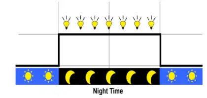
- Light ON/OFF(default)

- Turn-On voltage (Adjustable): 5V(12Vsystem), delay10min.
- Turn-Off voltage (Adjustable): 6V(12Vsystem), delay10min.
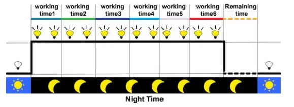
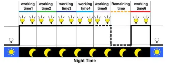
- Light ON + Timer
Light ON + Timer1
Light ON + Timer2
Light ON + Timer3
Item Default※ Range Mode1 Mode2/3 0-2.6A(LS101240LPLI) LED Rated Current 0.35A 0-2.0A(LS102460LPLI) 0-4.0A(LS101260/2024120LPLI) Timer1 2H 1H 00:00—23:59H LED Rated Current Percentage 100% 100% 0—100% Timer2 2H 1H 00:00—23:59H LED Rated Current Percentage 80% 50% 0—100% Timer3 LED Rated Current Percentage 2H 50%
0H 0%
00:00—23:59H 0—100%
Timer4/5 LED Rated Current Percentage 0H 0%
0H 0%
00:00—23:59H 0—100%
Timer6 LED Rated Current Percentage 0H 0%
2H 100%
00:00—23:59H 0—100%
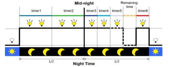
- Time Control
Control the load on/off time by setting the real-time clock. - Intelligent Power Mode
When the battery voltage goes lower than the “Reduce Power Start Voltage (adjustable),” the intelligent power reduction mode is enabled. The LED output current is automatically reduced in linear with the battery’s voltage drop. When the battery voltage goes lower than the “Reduce Power End Voltage (adjustable),” the LED output current is 2% of the rated load current. The minimum percentage can be set to 1%). Also, when the battery voltage is higher than “Reduce Power Start Voltage,” the controller exits the intelligent power reduction mode.
Setting Operation
There are two methods to check and set the controller’s parameters:

- IR Remote Controller—RC-10
- Super Parameter Programmer—FC-01
This method can realize one-key setting operation which is suitable for bulk quantity products setting or applied in the projects.
NOTE: Please refer to the user manual of handheld device.
Protection
| Protection | Conditions | Status |
| PV Reverse Polarity | When the battery is correctly connecting, the PV can be reversed. | The controller is no damage |
| Battery Reverse Polarity | When the PV is not connected, or the connection is reversed, the battery can be reversed. WARNING: Controller is damaged when the PV connection is correct, and the battery connection is reversed! | |
| Battery Over Voltage | The battery voltage reaches the OVD | Stop charging |
| Battery Over Discharge | The battery voltage reaches the LVD | Stop discharging |
| Battery Overheating | The temperature sensor is higher than 65℃ | Output is OFF |
| The temperature sensor is less than 55℃ | Output is ON | |
| Li-battery Low Temperature★ | The temperature sensor is less than the low-temperature value | Stop charging or discharge |
| The temperature sensor is higher than the low-temperature value | Begin charging or discharge | |
| Load Short Circuit | Load current ≥2.5 times rated current In one short circuit, the output is OFF 5s; Two short circuits, the output is OFF 10s; Three short circuits, the output is OFF 15s; Four short circuits, the output is OFF 20s; Five short circuits, the output is OFF 25s; Six short circuits, the output is OFF | Output is OFF Clear the fault: Restart the controller or wait for one night-day cycle (night time>3 hours). |
| Load Open Circuit(Load over voltage) | Max. load voltage≥68V One open circuit, the output is OFF 5s; Two open circuits, the output is OFF 10s; Three open circuits, the output is OFF 15s; Four open circuits, the output is OFF 20s; Five open circuits, the output is OFF 25s; Six open circuits, the output is OFF 5s; Seven open circuits, the output is OFF 5s | Output is OFF (Cycle to perform) |
If selecting a lithium battery, set the low-temperature value(LTV) according to the specification; otherwise, the lithium battery is damaged.
Troubleshooting
| Faults | Possible reasons | Troubleshooting |
| Charging LED indicator off during daytime when sunshine falls on PV modules properly | PV array disconnection | Confirm that PV and battery wire connections are correct and tight |
| No LED indicator | Min.9V can start up the controller. | Measure the battery voltage with a multi-meter. Min.9V can start up the controller. |
| Battery LED indicator green Fast Flashing | Battery over voltage | ①Disconnect the solar array and measure the battery voltage; ② Change the controller; ③ Change the battery |
| Battery LED indicator red | ①Battery over discharged | When the battery voltage is restored to or above setpoint (low voltage reconnect voltage), the load work |
| Battery Status LED red indicator flashing | Battery Overheating | The controller automatically stops working. When the temperature is below 50 ºC, the controller resumes |
| All the LED indicator flashing(battery red | System voltage error | Check whether the battery voltage matches the controller’s working |
| indicator flashing) | voltage. Please change to a suitable battery or reset the working voltage | |
| Powering on normally, the load is off | ①The connecting wires are error or virtual connection ②Load mode is wrong ③The controller does not match with the LED light. ④Output short circuit | ①Check the connecting cables ②Check the load mode and parameter ③The voltage of the LED light source is not in the output voltage range of the controller ④Check the connecting cables and LED light source |
| The dimming function is invalid | The controller does not match with the LED light source. This product is a step-up current control; if the input voltage is lower than the rated voltage, it is not working. | ① Relace the LED light ②Reduce system rated voltage grade, and replace the product model For example, switch the 24V system to the 12V system, and replace the corresponding controller. |
① When the battery is over discharged, the battery indicator will be red. The load will be off all the time before the voltage is more than the Low Voltage Reconnect Voltage (LVRV). To judge the system is normal or not, firstly measuring the battery voltage, whether it is more than LVRV; if not, restarting the controller to detect the load.
Technical Specifications
| Models Item | LS101240LPLI | LS101260LPLI | LS102460LPLI | LS2024120LPLI | ||||
| Nominal system voltage | 12VDC | 12/24VDC◆ | ||||||
| Rated charge current | 10A | 10A | 10A | 20A | ||||
| Max. PV open circuit voltage | 30V | 50V | ||||||
| Battery input voltage range | 9~16V | 9~32V | ||||||
| Max. output power | 40W/12V | 60W/12V | 30W/12V 60W/24V | 60W/12V 120W/24V | ||||
| Max. output Current | 2.6A | 4.0A | 2.0A | 4.0A | ||||
| Output voltage range | (Max. Battery Voltage +2V)~60V | |||||||
| Load open circuit voltage | 60V | |||||||
| Maximum output efficiency | 96% | |||||||
| Output current control accuracy | ≤2% | |||||||
| Battery Type | Lead-acid battery: Sealed(default)/Gel/Flooded/User | |||||||
| Lithium battery:LiFePO4/Li-NiCoMn/User | ||||||||
| Lead-acid battery | Equalization Voltage▼ | Sealed:14.6V; Flooded:14.8V;User:9-17V | ||||||
| Boost Voltage▼ | Sealed:14.4V;Gel:14.2V;Flooded:14.6V;User:9-17V | |||||||
| Float Voltage▼ | Sealed/Gel/Flooded:13.8V; User:9-17V | |||||||
| Reduce Power Start Voltage ▼ | Sealed/Gel/Flooded:12.2V; User:9-17V | |||||||
| Reduce Power End Voltage ▼ | Sealed/Gel/Flooded:12.0V; User:9-17V | |||||||
| Low Voltage Reconnect Voltage▼ | Sealed/Gel/Flooded:12.6V; User:9-17V | |||||||
| Low Voltage Disconnect Voltage▼ | Sealed/Gel/Flooded:11.1V; User:9-17V | |||||||
| Lithium battery | Boost Voltage▼ | LiFePO4(4s):14.5V/Li-NiCoMn(3s):12.5V/User:9-17V | ||||||
| Reduce Power Start Voltage ▼ | LiFePO4(4s):12.8V/Li-NiCoMn(3s):12.2V/User:9-17V | |||||||
| Reduce Power End Voltage ▼ | LiFePO4(4s):12.0V/Li-NiCoMn(3s):10.5V/User:9-17V | |||||||
| Low Voltage Reconnect Voltage▼ | LiFePO4(4s):12.8V/Li-NiCoMn(3s):10.5V/User:9-17V | |||||||
| Low Voltage Disconnect Voltage▼ | LiFePO4(4s):11.1V/Li-NiCoMn(3s):9.3V/User:9-17V | |||||||
| Self-consumption | ≤18mA(12V);≤23mA(24V) | |||||||
| Charge Circuit Voltage Drop | ≤0.14V | |||||||
| Com. way | IR | |||||||
| Com. distance of IR | <6m | |||||||
| Working environment temperature | -40℃~+55℃ | |||||||
| Enclosure | IP68(1.5m,72h) | |||||||
| Overall dimension(mm) | 87x60x22.8 | 87x63x24.8 | 87x63x24.8 | 108.5x88x25.6 | ||||
| Mounting dimension(mm) | 80 | 80 | 80 | 100.5 | ||||
| Mounting hole size(mm) | Φ4 | Φ4 | Φ4 | Φ5 | ||||
| Power cable | PV/BAT:14AWG/2.5mm2 LOAD: 18AWG/1.0mm2 | PV/BAT: 12AWG/4.0mm2LOAD:18AWG/1.0mm2 | ||||||
| Net weight | 0.18kg | 0.21kg | 0.21kg | 0.40kg | ||||
- When selecting a lithium battery, the controller cannot automatically recognize the nominal system voltage and has no temperature compensation.
- The parameters are the 12V system at 25 ºC, double the values in the 24V system.
Disclaimer
This warranty does not apply under the following conditions:
- Damage from improper use or use in an unsuitable environment.
- PV or load current, voltage, or power is exceeding the rated value of the controller.
- The controller’s working temperature exceeds the limit working temperature.
- User disassembly or attempted to repair the controller without permission.
- The controller is damaged due to natural elements such as lighting.
- The controller is damaged during transportation and shipment.
Tel: +86-10-82894896/82894112/+86-752-3889706
Website: www.epever.com


