![]()
INSTALLATION INSTRUCTIONS FOR THE
HALL-EFFECT ROTARY POSITION SENSORS,
RTP SERIES
GENERAL INFORMATION
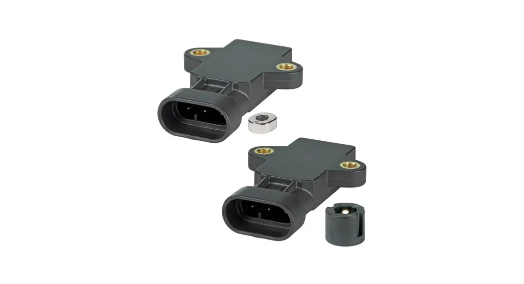
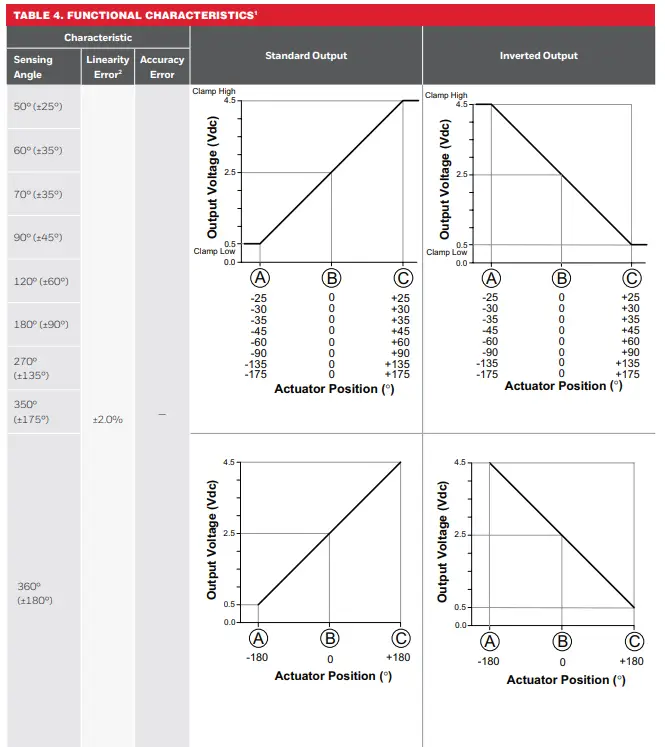
The RTP Series Hall-effect Rotary Position Sensors provide non-contact sensing in harsh transportation and industrial applications at a competitive cost. These products use a magnetically biased, Hall-effect integrated circuit (IC) to sense rotary movement of the actuator over a set operating range. Rotation of the actuator changes the magnet’s position relative to the IC. The resulting flux density change is converted to a linear output.
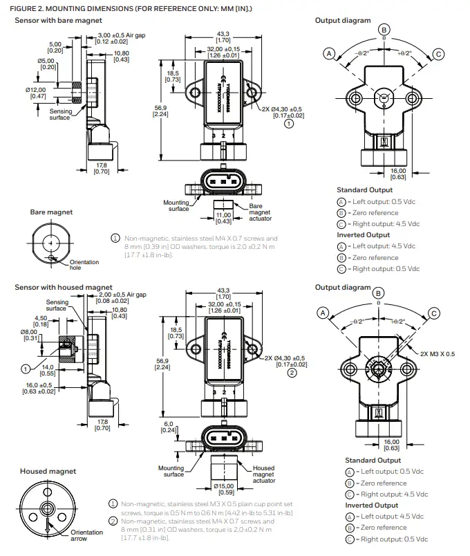
MOUNTING INFORMATION (see Figures 1 and 2)
Housed magnet actuator
- Locate the sensor and the magnet in the desired position. Ensure the air gap between the sensor and the magnet will not exceed that noted in Table 2.
- Clamp the sensor on the customer-provided mounting plate and place the magnet on the customer-provided mounting shaft. Ensure the orientation arrow on the magnet points toward the connector end of the sensor.
- Apply the supply voltage to the sensor and monitor the output voltage. When the output voltage is at the midpoint as shown in Table 4, tighten the set screws on the magnet. The sensor angle is 0°.
- If needed for harsh applications, apply a suitable thread locking compound to all screw threads.
Bare magnet actuator
- Locate the sensor and the magnet in the desired position. Ensure the air gap between sensor and magnet will not exceed that noted in Table 2.
- Clamp the sensor on the customer-provided mounting plate and place the magnet on the desired actuator. Ensure the orientation hole on the magnet points towards the connector end of the sensor.
- Apply the supply voltage to the sensor and monitor the output voltage. When the output voltage is at the midpoint as shown in Table 4, mount the magnet. The sensor angle is 0°.
- If needed for harsh applications, apply a suitable thread locking compound to all screw threads.
| TABLE 1. ELECTRICAL SPECIFICATIONS | ||
| Characteristic | LV (Low Voltage) | HV (High Voltage) |
| Supply voltage: | 5 ±0.5 Vdc | 10 Vdc to 30 Vdc |
| Supply current: normal during output to ground short | 20 mA max. 25 mA max. | 32 mA max. 47 mA max. |
| Output: standard inverted | 0.5 Vdc to 4.5 Vdc ratiometric 4.5 Vdc to 0.5 Vdc ratiometric | 0.5 Vdc to 4.5 Vdc non-ratiometric 4.5 Vdc to 0.5 Vdc non-ratiometric |
| Output signal delay | 4 ms typ. | |
| Overvoltage protection | 10 Vdc | — |
| Reverse polarity protection | -10 Vdc | -30 Vdc |
| Output to ground short circuit protection | continuous | |
| Resolution | 12 bit | |
| Output load resistance (pull down to ground) | 10 kOhm typ. | |
| EMI: radiated immunity | 100 V/m per ISO11452-2 from 200 MHz to 1000 MHz | |
| conducted immunity | 100 mA BCI per ISO11452-4 from 1 MHz to 200 MHz | 100 mA BCI per ISO11452-4 from 1 MHz to 400 MHz |
| EMC | exceeds CE, UKCA requirements | |
| TABLE 2. MECHANICAL SPECIFICATIONS | ||
| Characteristic | LV (Low Voltage) | HV (High Voltage) |
| Expected life | infinite rotation | |
| Air gap: bare magnet actuator housed magnet actuator misalignment | 3,00 mm ±0,5 mm [0.12 in ±0.02 in] 2,00 mm ±0,5 mm [0.08 in ±0.02 in] 2.002,00 in [0.08 in] | |
| Material: magnet sensor housing housed magnet overmold sensor/housed magnet bushing | NdFeB PBT plastic PPS plastic brass | |
| Mating connector | AMP Superseal 282087-1 | |
| Mechanical end stop | no | |
| Mounting screw sizes: sensor to mounting surface housed magnet actuator to customer-provided mounting pin | non-magnetic, stainless steel M4 X 0,7 screws and 8 mm [0.39 in] OD washers non-magnetic, stainless steel, M3 X 0.5 plain cup point set screws | |
| Approvals | CE, UKCA | |
| TABLE 3. ENVIRONMENTAL SPECIFICATIONS | ||
| Characteristic | LV (Low Voltage) | HV (High Voltage) |
| Operating temperature range | -40 °C to 125 °C [-40 °F to 257 °F] | |
| Ingress protection | IP69K | |
| Media compatibility | heavy transportation fluids | |
| Shock | 50 G peak | |
| Vibration | 20 G peak | |
| Salt fog | bare magnet: 96 hr for as per ASTM B117 housed magnet: 240 hr per ASTM B117 | |
NOTICE
Ferrous material or magnet material more than 300 Gauss within 10 mm [0.39 in] from sensor boundary may impact sensor performance.
FIGURE 1. SENSOR AND HOUSED MAGNET ACTUATOR MOUNTING INFORMATION (FOR REFERENCE ONLY: IN/[MM].)
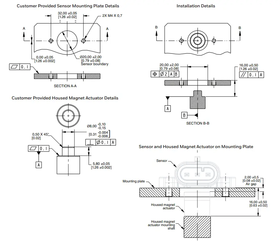
Notes:
- See Figure 2 for references to BAC.
- Linearity error is the deviation of the measured value from the best fit line and is the quotient of the measured output ratio deviation from the best fit line at the measured temperature to the best fit line output ratio span at the measured temperature.
![]() WARNING
WARNING
PERSONAL INJURY
DO NOT USE these products as safety or emergency stop devices or in any other application where failure of the product could result in personal injury.
Failure to comply with these instructions could result in death or serious injury.
![]() WARNING
WARNING
MISUSE OF
DOCUMENTATION
- The information presented in this product sheet is for reference only. Do not use this document as a product installation guide.
- Complete installation, operation, and maintenance information is provided in the instructions supplied with each product.
Failure to comply with these instructions could result in death or serious injury.
WARRANTY/REMEDY
Honeywell warrants goods of its manufacture as being free of defective materials and faulty workmanship during the applicable warranty period. Honeywell’s standard product warranty applies unless agreed to otherwise by Honeywell in writing; please refer to your order acknowledgment or consult your local sales office for specific warranty details. If warranted goods are returned to Honeywell during the period of coverage, Honeywell will repair or replace, at its option, without charge those items that Honeywell, in its sole discretion, finds defective. The foregoing is buyer’s sole remedy and is in lieu of all other warranties, expressed or implied, including those of merchantability and fitness for a particular purpose. In no event shall Honeywell be liable for consequential, special, or indirect damages.
While Honeywell may provide application assistance personally, through our literature and the Honeywell web site, it is buyer’s sole responsibility to determine the suitability of the product in the application.
Specifications may change without notice. The information we supply is believed to be accurate and reliable as of this writing. However, Honeywell assumes no responsibility for its use.
FOR MORE INFORMATION
Honeywell Advanced Sensing Technologies services its customers through a worldwide network of sales offices and distributors. For application assistance, current specifications, pricing or the nearest Authorized Distributor, visit our website or call:
USA/Canada +1 302 613 4491
Latin America +1 305 805 8188
Europe +44 1344 238258
Japan +81 (0) 3-6730-7152
Singapore +65 6355 2828
Greater China +86 4006396841
![]()
Honeywell
Advanced Sensing Technologies
830 East Arapaho Road
Richardson, TX 75081
sps.honeywell.com/ast
32307666-B-EN IL50 | B | 01/22
© 2022 Honeywell International Inc. All rights reserved.


