
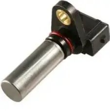
Honeywell SNDH-T4C-G0 Speed Sensor Hall
DESCRIPTION
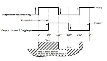
The SNDH-T Series is a dual differential Hall-effect sensor that provides speed and direction information using a quadrature output with signals 90° phase shifted from each other. Target direction is determined by output lead/lag phase shifting. This product is designed for applications where extremely high resolution is required at wide frequency ranges, 1 Hz to 15 kHz, and large air gaps. BiCMOS (bipolar complementary metal-oxide-semiconductor). Hall-effect technology, using advanced digital signal processing for dynamic off-set cancellation, provides enhanced air gap performance and phase shift accuracy over most conditions.
Unique patented (pending) IC (integrated circuit) packaging provides output phase shift tolerancing with enhanced accuracy. The robust package is automotive under-the-hood grade for most environmental conditions, as well as EMI (electromagentic interference) hardened. Multiple connection options are available. Package design includes an O-ring seal for pressure applications and a fixed mounting flange.
FEATURES
- Hall-effect magnetic sensing technology
- Dual differential Hall provides enhanced target resolution
- Advanced performance dynamic offset self-calibration
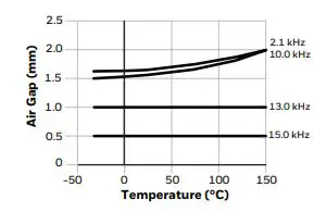
- Air gap up to 2 mm [0.08 in]
- Near zero speed
- Automotive under-the-hood packaging integrity
- EMI hardened
- High-frequency switching capability: 1 Hz to 15 kHz
- Wide operating temperature range: -40ºC to 150ºC [-40°F to 302°F]
- Multiple connector options
- Short circuit protection
- Reverse voltage protection
- Open collector output
- Low jitter output
- O-ring seal

POTENTIAL TRANSPORTATION APPLICATIONS
- Steering position
- Tachometers/counters
- Encoders
- Speed and direction of gears and shafts in transmissions, hydraulic motors, pumps and gearboxes

PORTFOLIO
The SNDH-T Series is part of a portfolio of electronic speed and position sensors that use a variety of technologies to detect speed, direction, or position of a moving ferrous metal or magnetic target.
QUADRATURE SPEED AND DIRECTION SENSORS SNDH-T SERIES
| TABLE 1. ELECTRICAL SPECIFICATIONS | ||
| Characteristic | Parameter | Comment |
| Voltage: supply max. continuous supply | 4.5 V to 18 V 18 V | — — |
| Output signal: type duty cycle1 phase shift high low load current rise time fall time frequency | square wave 50% ±10% 90° ±20° >Vs – 0.5 V <0.5 V 20 mA max. 10 us max. 1 us max. 1 Hz to 15 kHz | Two channel, phase shifted by 90° either channel, may lead or lag/push/pull. See Figures 2, 3, 4, 5 for recommended orientation. Using recommended target tooth/slot2. See Figures 2, 3, 4, 5 for recommended orientation. Applies to each output at all conditions. Dependent on load resistor. — Frequencies >10 kHz may be dependent on target geometry and air gap. |
| Short circuit protection | 80 mA max. | all conditions |
| Supply current: normal max. | 12 mA 18 mA | all conditions |
| Reverse voltage | -18 V max. | continuous |
- Duty cycle = Time high/time total.
- >Vpull – up – 0.5 V if not the same as Vs.
| TABLE 2. MECHANICAL SPECIFICATIONS | |
| Characteristic | Parameter |
| Sensing air gap | 0,0 mm to 2,0 mm [0.0 in to 0.08 in] |
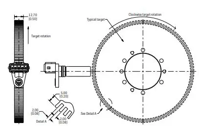
| Target: width1 slot width2 tooth width2 tooth height3 | >5,0 mm [0.20 in] recommended; 12,7 mm [0.5 in] typ. 2,0 mm [0.08 in] recommended 2,0 mm [0.08 in] recommended >3,0 mm [0.12 in] recommended; 5,0 mm [0.20 in] typ. |
| Sensor misposition to target | ±1.5 mm |
| Materials: insert housing bushing O-ring cable5 | plastic Valox® K4560 304 stainless steel brass fluorocarbon (Viton™) EVA, four conductor, 36 AWG, 28 strand, ø5,2 mm [ø0.20 in] jacket |
| Mounting: bore size4 torque | ø15,05 mm to ø15,15 mm [ø0.60 in to ø0.61 in] 10 Nm [88.5 in-lb] max. with M6 X 1.0 bolt |
- Narrower targets may limit axial offsets.
- Other geometry may be suitable.
- Shorter tooth heights may limit maximum air gap performance.
- Application is dependent.
QUADRATURE SPEED AND DIRECTION SENSORS SNDH-T SERIES
| TABLE 3. ENVIRONMENTAL SPECIFICATIONS | ||
| Characteristic | Condition | Parameter |
| EMI: radiated immunity bulk current injection ESD fast transient burst | 400 Hz to 2 GHz 20 MHz to 400 MHz against the connector (150 pF, 330 Ohm) EN 60947-5-2/A1:2012 | 100 V/m 60 mA 16 kV air and 8 kV contact EN61000-4-4 Level 4 |
| Operating temperature | continuous | -40°C to 150°C [-40°F to 302°F] |
| Thermal shock, air to air | 0.5 hr dwell, <105 transition | -40°C to 150°C [-40°F to 302°F] |
| Humidity | 95% humidity at 90°C [194°F] | 168 hr |
| Salt fog | DIN IEC 6872-11 | 96 hr |
| Thermal saline dunk | 105°C to 0°C [221°F to 32°F] air to liquid, 5% saline | 5 dunks |
| High temperature exposure with power | — | 1000 hr at 150°C [302°F] |
| Mechanical shock | — | 50 g |
| Vibration | — | 30 g, 10 Hz to 2 kHz |
| Sensor degree of protection | — | IP69K |
| Resistance to fluids | — | general under-the-hood automotive fluids |
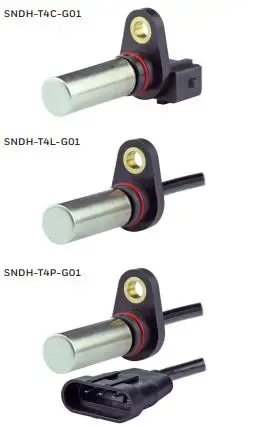
| TABLE 4. CATALOG LISTINGS | |
| Catalog Listing | Description |
| SNDH-T4C-G01 | SNDH-T Series, quadrature speed and direction sensor, stainless steel housing, 45 mm [1.77 in] housing length, integral connector, straight exit, |
| SNDH-T4L-G01 | SNDH-T Series, quadrature speed and direction sensor stainless steel housing, 45 mm [1.77 in] housing length, 555 mm [21.85 in] cable with leads, straight exit, |
| SNDH-T4P-G01 | SNDH-T Series, quadrature speed and direction sensor stainless steel housing, 45 mm [1.77 in] housing length, connector with 203,8 mm [8.02 in] cable, straight exit |
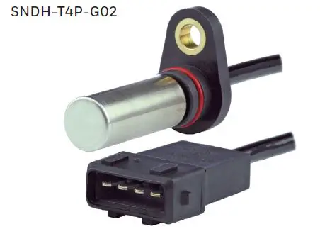
| SNDH-T4P-G02 | SNDH-T Series, quadrature speed and direction sensor, stainless steel housing, 45 mm [1.77 in] housing length, connector with 555 mm [21.85 in] cable, straight exit, |
- Figure 1. Sensor Output

- Figure 2. Temperature Air Gap Frequency Derating Curve

- Figure 3. SNDH-T4C-G01 Dimensional Drawings (For reference only: mm [in])


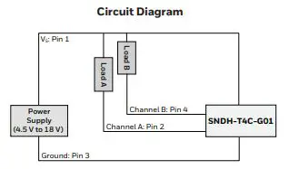
Note: The load resistor values should be such that the output current does not exceed the maximum load current of 20 mA. Use Ohm’s Law to calculate the load resistor based on the supply/load voltage used: Rload = Vs / 0.02 A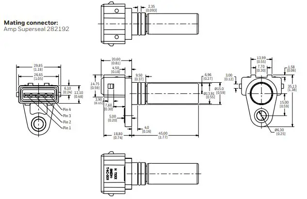
| PINOUT | |||
| Pin 1 | Pin 2 | Pin 3 | Pin 4 |
| (+) | Channel A | (-) | Channel B |
Figure 4. SNDH-T4L-G01 Dimensional Drawings (For reference only: mm [in])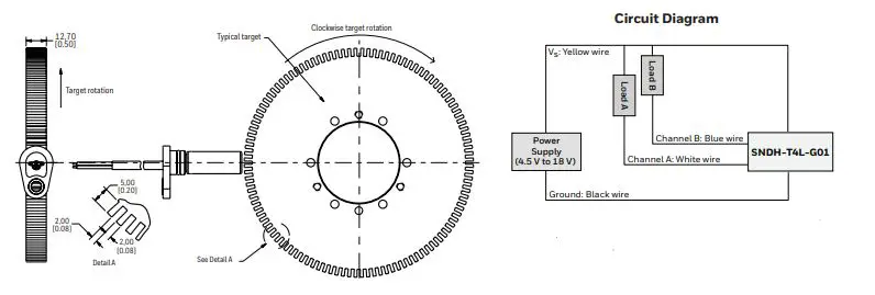
Note: The load resistor values should be such that the output current does not exceed the maximum load current of 20 mA. Use Ohm’s Law to calculate the load resistor based on the supply/load voltage used: Rload = Vs / 0.02 A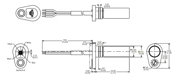
| LEADWIRE ASSIGNMENT | |||
| Yellow | Black | White | Blue |
| (+) | (-) | Channel A | Channel B |
Figure 5. SNDH-T4P-G01 Dimensional Drawings (For reference only: mm [in])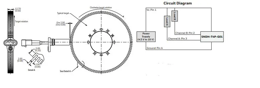
Note: The load resistor values should be such that the output current does not exceed the maximum load current of 20 mA. Use Ohm’s Law to calculate the load resistor based on the supply/load voltage used: Rload = Vs / 0.02 A
Mating connector:
Amp Superseal 282088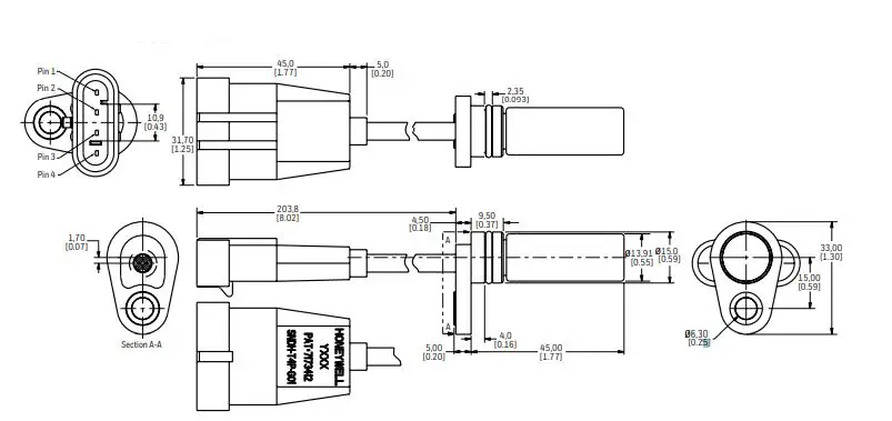
| PINOUT | |||
| Pin 1 | Pin 2 | Pin 3 | Pin 4 |
| (+) | Channel B | Channel A | (-) |
Figure 6. SNDH-T4P-G02 Dimensional Drawings (For reference only: mm [in])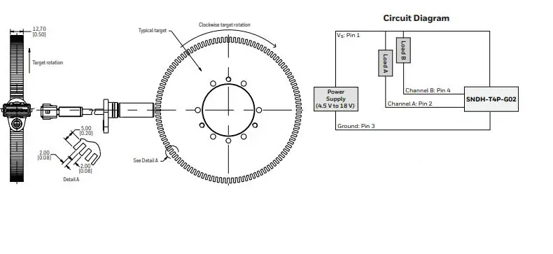
Note: The load resistor values should be suchthat the output current does not exceed the maximum load current of 20 mA. Use Ohm’s Law to calculate the load resistor based on the supply/load voltage used: Rload = Vs / 0.02 A
Mating connector:
Amp Superseal 282192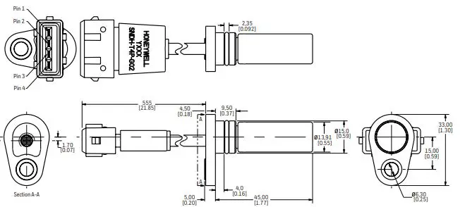
| PINOUT | |||
| Pin 1 | Pin 2 | Pin 3 | Pin 4 |
| (+) | Channel A | (-) | Channel B |
WARRANTY/REMEDY
Honeywell warrants goods of its manufacture as being free of defective materials and faulty workmanship during the applicable warranty period. Honeywell’s standard product warranty applies unless agreed to otherwise by Honeywell in writing; please refer to your order acknowledgment or consult your local sales office for specific warranty details. If warranted goods are returned to Honeywell during the period of coverage, Honeywell will repair or replace, at its option, without charge those items that Honeywell, in its sole discretion, finds defective. The foregoing is buyer’s sole remedy and is in lieu of all other warranties, expressed or implied, including those of merchantability and fitness for a particular purpose. In no event shall Honeywell be liable for consequential, special, or indirect damages. While Honeywell may provide application assistance personally, through our literature and the Honeywell web site, it is buyer’s sole responsibility to determine the suitability of the product in the application. Specifications may change without notice. The information we supply is believed to be accurate and reliable as of this writing. However, Honeywell assumes no responsibility for its use.
WARNING PERSONAL INJURY
- DO NOT USE these products as safety or emergency stop devices or in any other application where failure of the product could result in personal injury.
- Failure to comply with these instructions could result in death or serious injury.
- WARNING MISUSE OF DOCUMENTATION
- The information presented in this product sheet is for reference only. Do not use this document as a product installation guide.
- Complete installation, operation, and maintenance information is provided in the instructions supplied with each product. Failure to comply with these instructions could result in death or serious injury.
FOR MORE INFORMATION
Honeywell Sensing and Safety Technologies services its customers through a worldwide network of sales offices and distributors. For application assistance, current specifications, pricing or the nearest Authorized Distributor, visit sps.honeywell.com/ast or call:
- USA/Canada +1 302 613 4491
- Latin America +1 305 805 8188
- Europe +44 1344 238258
- Japan +81 (0) 3-6730-7152
- Singapore +65 6355 2828
- Greater China +86 4006396841
Valox® is a registered trademark of Sabic Global Technologies B.V.
Viton™ is a trademark The Chemours Company FC, LLC.Sensing and Safety Technologies
830 East Arapaho Road
Richardson, TX 7508
sps.honeywell.com/astValox® is a registered trademark of Sabic Global Technologies B.V. Viton™ is a trademark The Chemours Company FC, LLC. 000641-7-EN | 7 | 10/22 © 2022 Honeywell International Inc. All rights reserved.


