14+ INSTRUCTION MANUAL
Operation under adult’s supervision.
Please read and understand the instructions in the manual before use and assembly.
READY-TO-RUN COPYRIGHT RESERVED
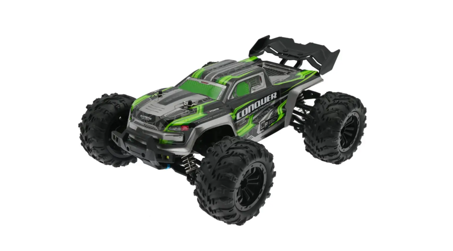
Model:16102 Race Truck
Note: To spare the space on package, the wing is dismantled at factory. Please install it before driving.
– To avoid getting scratched during shipment, each body is protected and attached with the transparent thin film. Please rip off the film before driving.
– Please fully charge the battery pack before each use.
– Children under aged 14 must not operate this product unless they are closely supervised by adults.
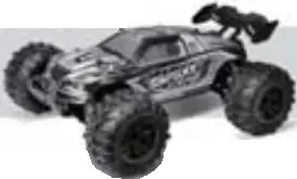
4WD OFF-ROAD VEHICLE
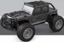
Model:16103 Cross-Country Truck
HOBBY GRADE R/C VEHICLE
1/16 SCALE
1/16 SCALE 4WD BATTERY POWERED R/C VEHICLE
1/16 R/C VEHICLE
General Information
![]() This Manual is subject to change without prior notification.
This Manual is subject to change without prior notification.![]() This product is NOT a toy, and not intended for users under 14 years of age, unless closely supervised by an adult. The specifications and images in the manual may vary from the actual product.
This product is NOT a toy, and not intended for users under 14 years of age, unless closely supervised by an adult. The specifications and images in the manual may vary from the actual product.![]() Never operate the vehicle on public streets. This could cause traffic accidents, personal injury and/or property damage. This vehicle is ONLY be driven on the open track which is for RC cars. Do NOT handle this vehicle to chase pets or other animals.
Never operate the vehicle on public streets. This could cause traffic accidents, personal injury and/or property damage. This vehicle is ONLY be driven on the open track which is for RC cars. Do NOT handle this vehicle to chase pets or other animals.![]() The receiver, steering servo and other electronics installed in this vehicle are merely splash water-resistant. Do not immerse this vehicle into water.
The receiver, steering servo and other electronics installed in this vehicle are merely splash water-resistant. Do not immerse this vehicle into water.![]() Regular cheek on the transmitter power is very important. Remove the batteries from the transmitter when not in use.
Regular cheek on the transmitter power is very important. Remove the batteries from the transmitter when not in use.![]() Replace with the fresh batteries if necessary. Do NOT run this vehicle by low power from transmitter. When this vehicle becomes stuck, do NOT force on throttle. Failure to do so will cause an abrupt damage to the motor and/or the ESC(Electronic Speed Controller).
Replace with the fresh batteries if necessary. Do NOT run this vehicle by low power from transmitter. When this vehicle becomes stuck, do NOT force on throttle. Failure to do so will cause an abrupt damage to the motor and/or the ESC(Electronic Speed Controller).![]() Check and clean the obstacles before running again.
Check and clean the obstacles before running again.
Be careful not to touch any moving parts when servicing this vehicle.![]() To prevent excessive r.p.m. from damaging the motor, and/or the drive train components, we suggest reducing the throttle while in the air during jumps.
To prevent excessive r.p.m. from damaging the motor, and/or the drive train components, we suggest reducing the throttle while in the air during jumps.![]() Never attempt to re-assemble motor, ESC, and receiver as these have been precisely calibrated at factory.
Never attempt to re-assemble motor, ESC, and receiver as these have been precisely calibrated at factory.![]() Always apply the factory optional/tooling parts to this vehicle.
Always apply the factory optional/tooling parts to this vehicle.
To upgrade this vehicle requires the user to upgrade the entire radio/driving system (such as motor, ESC, receiver and so forth.) They should be strictly matched.![]() To run this vehicle, turn on the transmitter (radio controller) first and then the receiver. To stop running this vehicle, turn off the receiver first, and then the transmitter).
To run this vehicle, turn on the transmitter (radio controller) first and then the receiver. To stop running this vehicle, turn off the receiver first, and then the transmitter).![]() Erect the receiver antenna (if it comes with this vehicle) for best receiving performance. Never cut the receiver antenna (if it comes with this vehicle). Otherwise, it could lose control of the vehicle.
Erect the receiver antenna (if it comes with this vehicle) for best receiving performance. Never cut the receiver antenna (if it comes with this vehicle). Otherwise, it could lose control of the vehicle.
Installing batteries to transmitter
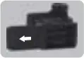 Press and slide down the battery cover as shown in the photo.
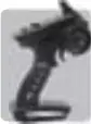
Proportional 2.4GHz Transmitter
![]() 3x ‘AA’ Size Batteries for transmitter (Not Included)
3x ‘AA’ Size Batteries for transmitter (Not Included)
- Use the batteries of same brand.
- Do not mix old and new batteries in use.
- Remove the batteries from the transmitter when not in use.
- Do not use leaky batteries.
Proportional 2.4GHz Transmitter
Warning: Do not move the trigger and the steering control while the transmitter is being bound with the ESC/Receiver. Failure to do so will lead to wrong signal input. Please operate the transmitter after binding operation has been fulfilled.
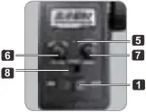
1) Power Switch (On/Off): Slide it to switch on or off power.
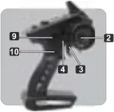
2) Steering Wheel: Proportionally operates the car’s right and left steering control.
3) Throttle Trigger: Pull to accelerate, release to slow down, and push it to brake. Center it and then push it a second time to reverse.
4) Trim Steering Tab: Using your throttle hand thumb on this tab to steer while using the trim buttons with your other hand. (presented for personal preference only.)
5) Power LED: It flashes rapidly during binding. After binding, it stops flashing and stays on solid. Please charge the transmitter’s batteries in case the LED goes slow flashes.
6) Steering Trim: it is used to make the vehicle drive in straight line. Turning the steering trim knob to adjust.
7) Speed: Turning down the knob all the way will reduce the maximum speed down to 30-40% of the maximum speed. Turning up the knob will increase max speed up to 100%.
8) Steering Reverse Switch: It allows you to electronically switch the direction of the steering servo travel. For instance, if you move the steering wheel to the right and your vehicle turns left, flip this switch to make it turn right.
9) and 10): Aux. Switches, disabled on this vehicle.
To drive the vehicle
(1) Switch on the transmitter, and then the vehicle.

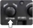
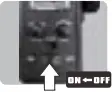
1) Slide the ON/OFF switch to switch on the transmitter.
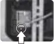
2) Press and hold the button on the ESC/Receiver for 2-3 seconds to switch on the ESC/Receiver.
(2) Checking up the throttle [Proportional]
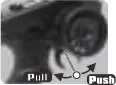

When you pull the throttle trigger, your vehicle accelerates forward. When you push the throttle trigger, your vehicle brakes. When you release the trigger then push again, your vehicle goes in reverse.
(3) Turning the steering trim to align the front wheels

If the front wheels are unaligned and off the center line the time you do not move the steering wheel on the transmitter, please turn the steering trim knob to align front wheels in line. Turn the steering trim clockwise to align them if the front wheels point to the left. Turn the steering trim anti-clockwise to align them if the front wheels point to the right.
(4) Tuning the speed switch

This Speed Switch is actually the throttle limiter. Turning down the knob all the way will reduce the maximum speed down to 30-40% of maximum speed. Turning up the knob will increase max speed up to 100%. It is strongly recommended that you learn from slow speed before trying to run the vehicle at high speeds.
(5) Steering Reverse Switch


It you move the steering wheel to the right and your vehicle turns left, flip the Steering Reverse Switch to make your vehicle turn right.
If you move the steering wheel to the left and your vehicle turns right, flip the Steering Reverse Switch to make your vehicle turn left.
To stop driving the vehicle
(1) Switch off the vehicle, and then the transmitter.
1) Press and hold the button on the ESC/Receiver for 2-3 seconds to switch off the ESC/Receiver.
2) Slide the ON/OFF switch to switch on the transmitter.
(2) Clean the vehicle with the soft cloth and brush, and store it in dry, cool and clean place away from the reach of children.
1 Disconnect and take out the battery pack if not in use.
1) Please disconnect and remove the battery pack from the chassis if the kit is not in use.
2) Clean the vehicle with the soft cloth and brush, and store it in a dry, cool and clean place away from the reach of children.
Maintenance Guide
![]() Check the chassis for any loose screws, especially the motor mounting screws. Tighten them if necessary.
Check the chassis for any loose screws, especially the motor mounting screws. Tighten them if necessary.![]() Any screws that are threaded directly into metal should be secured in place with thread lock. This will prevent the screws from loosening during use. Screws threaded into nylon or composite material do not require thread lock.
Any screws that are threaded directly into metal should be secured in place with thread lock. This will prevent the screws from loosening during use. Screws threaded into nylon or composite material do not require thread lock.![]() Check the condition of the transmitter batteries each item you drive your vehicle. If you think they might need replacement, do so before driving your vehicle again.
Check the condition of the transmitter batteries each item you drive your vehicle. If you think they might need replacement, do so before driving your vehicle again.![]() After a period of time the chassis will accumulate a lot of dirt and debris. This buildup should be cleaned off using a soft brush and compressed air.
After a period of time the chassis will accumulate a lot of dirt and debris. This buildup should be cleaned off using a soft brush and compressed air.![]() After cleaning the chassis and motor with compressed air, apply a couple of drops of lubricating oil to the motor bushings.
After cleaning the chassis and motor with compressed air, apply a couple of drops of lubricating oil to the motor bushings.![]() Check the suspension and steering system to ensure both are working smoothly without any binding.
Check the suspension and steering system to ensure both are working smoothly without any binding.![]() Check the electronics for any signs of damage. This includes the steering servo, ESC/Receiver, motor and wiring.
Check the electronics for any signs of damage. This includes the steering servo, ESC/Receiver, motor and wiring.![]() Periodically check the glue joints between the tires and wheels, looking for any signs of tire separation. If you notice any tire separation, re-glue the tire to the wheels using a good quality tire glue.
Periodically check the glue joints between the tires and wheels, looking for any signs of tire separation. If you notice any tire separation, re-glue the tire to the wheels using a good quality tire glue.
Charging The Battery Pack
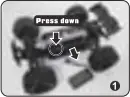
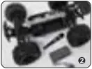
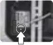
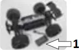
– Please disconnect and take out the battery pack from the chassis before charging it.
– Press down the tab as circled in the Photo 1 and take out the battery cover from the chassis, and then remove the battery pack from the chassis (Refer to the Photo 2).
– Children must NOT charge the battery pack without adults’ supervision.
– Charging must be fulfilled in a safe and spacious area away from heat and moist.
– Please be alert during charging. Do not charge the battery pack unattended.
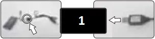
- Connected to USB charging slot or smart phone adaptor
– Connect the battery pack with the USB cable, and then connect USB cable to the USB charging slot or Ike smart phone adaptor (5V,2A) to charge the battery pack.
– It will take 3.5-4 hours before the battery pack is fully charged.
(Tip: Connecting to the smart phone adaptor (5V,2A) will shorten the charge time into 2.5-3 hours)
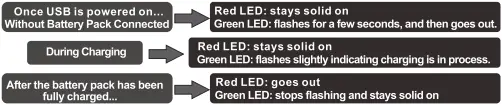
LEDs indications: Power LED: Red LED (Standby), Charging LED: Red LED
Battery Precaution
– Please fully charge the battery pack before each use.
– Please stop driving the vehicle in case the slow speed is observed. Stop and charge the battery pack. Please do not leave the battery pack uncharged for a long period of time. Failure to do so may shorten the battery life.
![]() WARNING!
WARNING!
– Do not throw batteries into fire. – Do not submerge batteries. – Do not store batteries close to any source of heat and humid. – Do not use leaky, broken and swollen battery pack. – Do not attempt to disassemble batteries.
Troubleshooting
A. The vehicle does not work at all:
1) Check to ensure that radio controller and car are switched on.
2) Check if there are damaged parts/wires/connectors, repair or replace if necessary.
3) Car battery is flat. Charge the battery pack.
B. The vehicle runs slowly:
1) Car battery is flat, Charge the battery pack.
2) Check if the vehicle is properly geared and no dirty or stripped gears are found.
3) Cheek the gear mesh for the motor pinion and spur gear.
4) Check if the moving parts have any problems and clean them immediately.
C. The throttle work’s but not the steering:
1) Check if the servo feels jammed, and try centering it gently if it does.
2) Check if the servo link is loose or if the servo is defective. Repair or replace if possible.
D. The vehicle steers, but there is no throttle control:
1) Check if there are damaged parts in the overall drive train.
2) Check the battery power both for radio controller and the car.
E. The vehicle drives noisily:
1) Check gear mesh between spur gear and motor pinion.
2) Check if there are stripped and/or dirty gears.
3) Check or any damage to any part throughout the drive train.
F. The vehicle does not steer the same amount in both directions.
1) Please adjust the steering trim until the steering center point is fixed.
G. Batteries can not be taken to charge:
1) Check if either the charger or the battery is damaged, or batteries are over-discharged.
Model:16101 Model:16102
Model:16103 Model:16201

Note: To spare the space on package, the wing is dismantled at factory. Please install it before driving.
LED LIGHT INSTALLATION
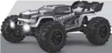
Note: The headlight is exclusively presented for vehicle 16101 and vehicle 16102.
The headlight, not installed onto the truck at factory, is provided in the packaging.
It is applied for personal preference. Please read and understand the instructions below before installing the headlight onto your truck.
For 16101 and 16102 only
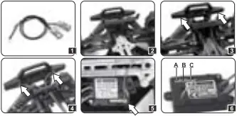
1) Collect the headlight from the package. (Figure 1)
2) The headlight must he mounted onto the slots at the back of the front bumper. (Figure 2)
3) Insert the lights into the slots as shown in Figure 3. Make sure the lights are securely fixed.
4) Close the slots with the covers, and lock up with the screws. (See Figure 4)
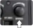
5) Plug in the headlight. Insert the headlight plug into the slot on the ESC/Receiver. (see Figure 5 and 6) 6) Slot A and Slot B: Headlight slots or TOP light Slots (Either of them can be applied to the headlight).
Slot C: applied for 5-wire Servo
For 16103 only
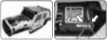

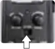
1) Headlight and top light are pre-mounted on the body.
2) Insert the headlight plug and the top light plug into the slots on the ESC/Receiver as shown in the photo above.
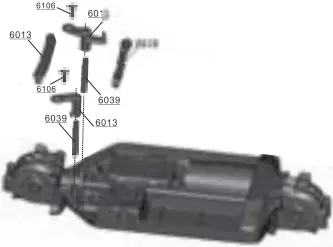
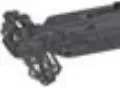
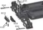
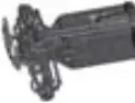
Assembly View-A
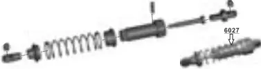
 Shock Absorber
 Shock Absorber
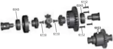
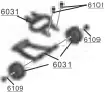
 Diff. Complete (Fr./Rr.)
 Diff. Complete (Fr./Rr.)
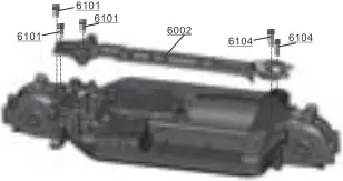
 Center Drive Shaft Assembly
 Center Drive Shaft Assembly
 Servo Saver Assembly
 Servo Saver Assembly
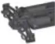
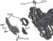
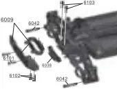
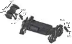
Assembly View-B
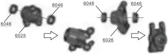
 Motor Mount Assembly
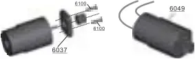 Motor Mount Assembly
Gear Box Housing Mount
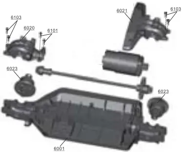
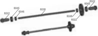
 Front/Rear Drive Shafts
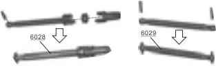 Front/Rear Drive Shafts
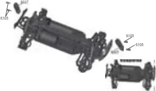
Assembly View-C
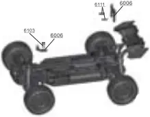
 ESC/Receiver Installation
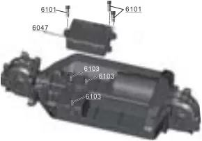 ESC/Receiver Installation
 Steering Assembly
 Steering Assembly
 Upper Deck Installation
 Upper Deck Installation
Assembly View-D
 Shock Towers Installation
 Shock Towers Installation
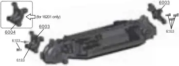
 Steering Hubs Rear Hubs
 Steering Hubs Rear Hubs
 Front Suspension Assembly
 Front Suspension Assembly
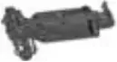 Completed
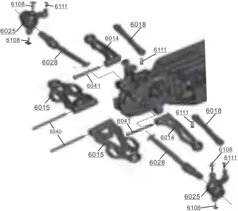
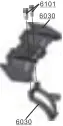
Assembly View-E
 Rear Suspension Assembly
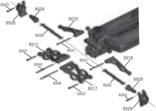 Rear Suspension Assembly
Completed

Front/Rear Bumper (only for 16201)
 Completed
 Completed
Assembly View-F
(for 16101, 16102)
 Completed
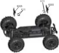
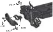
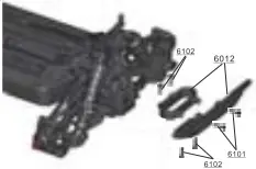
Front/Rear Bumper
 Completed
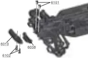
Shock Installation (only for 16101 and 16102)
Assembly View-G
Shock Installation (only for 16201)
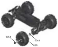
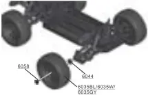
Wheel Installation
 Completed
Completed
Assembly View-H

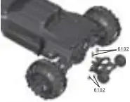
 Battery Pack Installation
 Battery Pack Installation
Body Post Installation
 Completed
 Completed
Assembly View-I
Wing Installation
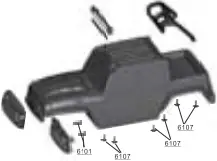
Body Installation


Assembly View-J
Wheelie Bar Installation
Completed ![]()
optional part exclusive for 16101 and 16102
Body Assembly (for 16103)
 Completed
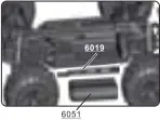
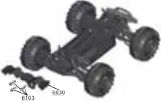
Front Bumper (for 16103)

Assembly View-K
Rear Bumper (for 16103)
 Completed
Wheel Installation (for 16103)
 Completed
Body Installation (for 16103)
 Completed
Spare Parts List-1
| 6001 | 6002 | 6003 | 6004 |
| | For 16101, 16102 and 16103 only
| For 16201 only
| |
| 6005 | 6006 | 6007 | 6008 |
| For 16101 and 16102
| For 16201 only
| For 16103 only
| For 16101 and 16102
|
| 6009 | 6010 | 6011 | 6012 |
| For 16101, 16102
| For 16201 only
| For 16103 only
| For 16103 only
|
| 6013 | 6014 | 6015 | 6016 |
 Front Lower Sway Arms(L/R) Front Lower Sway Arms(L/R) | |||
| 6017 | 6018 | 6019 | 6020 |
 Rear Lower Sway Arms(L/R) Rear Lower Sway Arms(L/R) |
 Body Post Mount
Spare Parts List-2
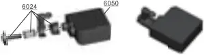
| 6021 | 6022 | 6023 | 6024 |
 Servo Saver Assembly Servo Saver Assembly | |||
| 6025 | 6026 | 6027 | 6028 |
 Rear Hub Carriers (L/R) Rear Hub Carriers (L/R) |  Shock Absorbers (2P) Shock Absorbers (2P) | ||
| 6029 | 6030 | 6031 | 6032 |
|
| For 16101, 16102 and 16201 | For 16101 and 16102 only
|
|
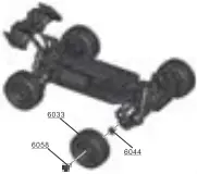
| 6033 | 6034 | 6035BL/6035W/6035GY | 6036 |
| For 16201
| For 16101 and 16102
| For 16103
| |
| 6037 | 6038 | 6039 | 6040 |
 Rear Drive Shafts/ Rear Wheel Shafts
 Wheelie Assembly
Spare Parts List-3
| 6041 | 6042 | 6043 | 6044 |
 Wheel Hex. (4P) Wheel Hex. (4P)
| |||
| 6045 | 6046 | 6047 | 6048 |
 Bell Bearing 6.35×9.5×3.2mm Bell Bearing 6.35×9.5×3.2mm | |||
| 6049 | 6050 | 6051 | 6052 |
 Motor w/motor pinion installed Motor w/motor pinion installed | |||
| 6053 | 6054 | 6055 | 6056 |
 Headlight Headlight | |||
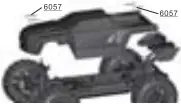
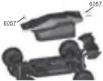
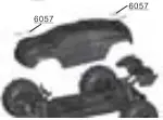
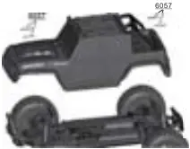
| 6057 | 6058 | 6059 | 6060 |
Spare Parts List-4
| 6061 | 6100 | 6101 | 6102 |
| For 16103 only
|
|
|
|
| 6103 | 6104 | 6105 | 6106 |
| 6107 | 6108 | 6109 | 6110 |
| 6111 | 6112 | ||
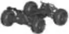
| Race Buggy Body | Race Truggy Body | Race Truck Body | Cross-Country Truck Body |
| For 16201 only
| For 16101 only
| For 16102 only
| For 16103 only
|
 Cross-country Truck Front Mask Light
Note: Part Photos may vary from the ones on your models.
14+ INSTRUCTION MANUAL
Operation under adult’s supervision.
READY-TO-RUN COPYRIGHT RESERVED
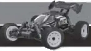
Model:16101 Race Truggy
Model:16201
Race Buggy
NOTE: This Equipment has been tested and found to comply with the limits for a Class B digital device, pursuant to Part 15 of the FCC rules. These limits are designed to provide reasonable protection against harmful interference in a residential installation. This equipment generates, uses and can radiate radio frequency energy and, if not installed and used in accordance with the instructions, may cause harmful interference to radio communications. However, there is no guarantee that interference will not occur in a particular installation. If this equipment does cause harmful interference to radio or television reception, which can be determined by turning the equipment off and on, the user is encouraged to try to correct the interference by one or more of the following measures:
– Reorient or relocate the receiving antenna.
– Increase the separation between the equipment and receiver.
– Connect the equipment into an outlet on a circuit different from that to which the receiver is connected.
– Consult the dealer or an experienced radio/TV technician for help.
Changes or modifications not expressly approved by the party responsible for compliance could void the user’s authority to operate the equipment.
This device complies with Part 15 of the FCC rules. Operation is subject to the following two conditions:
(1) this device may not cause harmful interference, and
(2) this device must accept any interference received, including interference that may cause undesired operation.
HOBBY GRADE R/C VEHICLE
1/16 SCALE
1/16 SCALE 4WD BATTERY POWERED R/C VEHICLE


