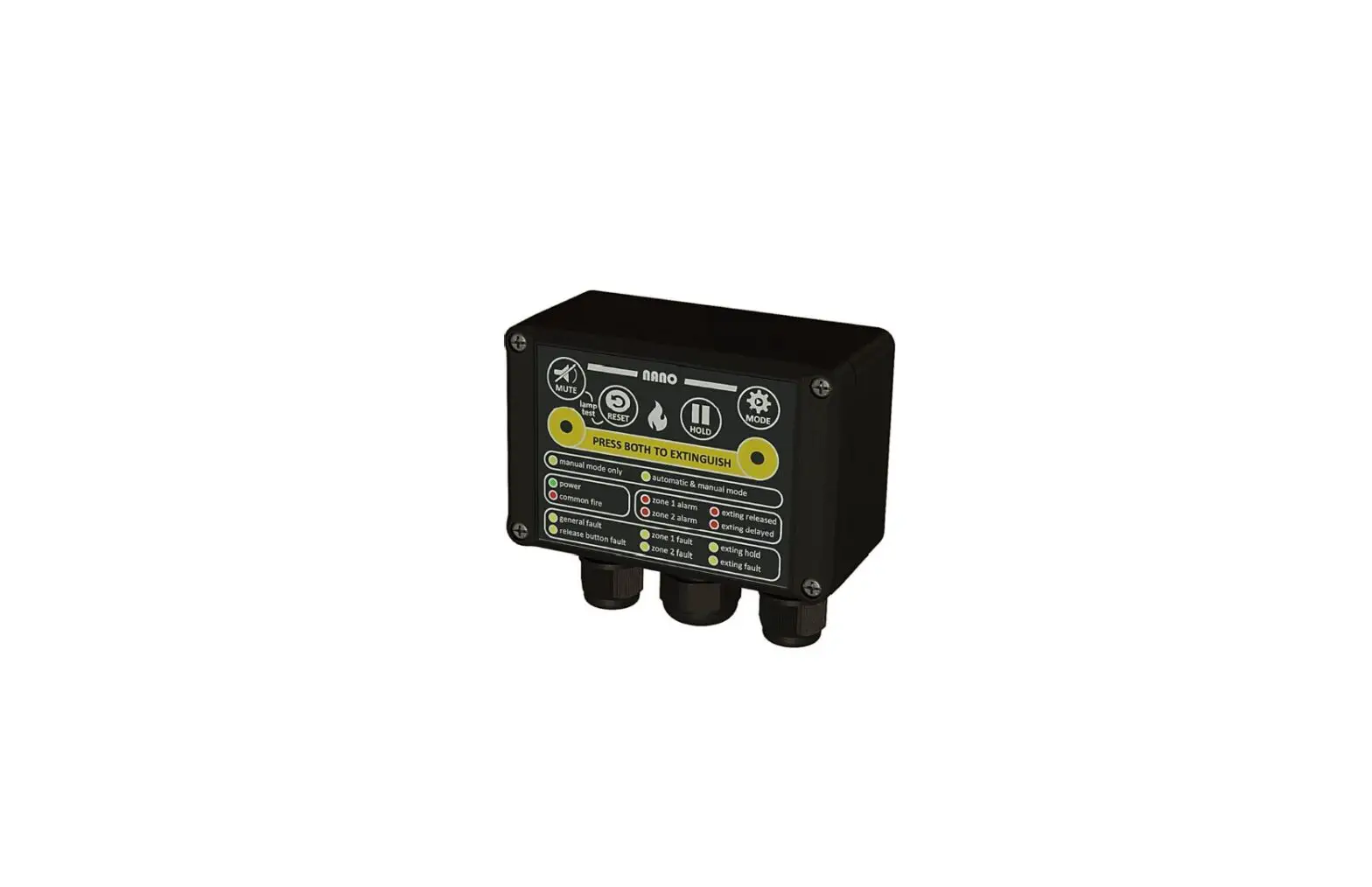
NANO RS-485 Fire Detection and Extinguishing Control Panel
DOCUMENT REVISION DETAILS
| Issue | Modification Detail | Author | Date |
| 1 | 1st publishing document | CvT | 01 / 11 / 2022 |
| 2 |
IMPORTANT NOTES – READ CAREFULLY
This manual should be thoroughly read and understood before installation and commissioning of the system is undertaken. This MODBUS manual is an integral part of the NANO manual version 2.2 of October 1, 2022.
The NANO, with the associated connections, must be installed, commissioned, and maintained by a skilled, knowledgeable, and competent personnel that is trained to perform this work. It is assumed that the personnel who commission the system is familiar with objective of the equipment and the technical terminology associated with this. Except for the backup battery there are no user-serviceable parts in the NANO.
The NANO/MAR system is not to be regarded as properly used when it is used without regard to any relevant information or advice relating to its use that has been made available by the supplier. The NANO/MAR system and the associated connections must be installed, commissioned, and maintained by a skilled, knowledgeable, and competent person or organization that is qualified to perform this work and is familiar with the objective of the equipment and the associated technical terminology. This equipment is not guaranteed unless the complete installation is installed and commissioned in accordance with the laid down local and/or national standards.
Reservations
The diagrams of operating principles of the NANO fire-/extinguisher system, included in this manual, are intended to support this manual and are therefore not intended and suitable for technical implementation or realization. No part of this manual may be reproduced, stored in an automated database, or made public in any form or by any means either electronically, mechanically or by photocopying, recording, or in any other way, without prior written permission from N2KB BV. The policy of the N2KB BV is one of continuous improvement and as such we reserve the right to make changes to product specifications at any time and without prior notice. Errors and omissions excepted.
INTRODUCTION
The NANO is designed to be used in a fully integrated system. Remote devices can read the status and parameters of the NANO by a digital bus system. The technology used is MODBUS. This is a very well-established bus technology that uses RS-485 as the underlaying physical layer. Please read the NANO
User Manual before using the device. This manual only manages the data bus usage.
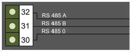
CONNECTING THE DATA BUS
RS-485 is a 3-wire bus. Two wires for the communication data and one wire for the ground connection.
Be aware that this ground wire must always be connected and physically kept together with the two data signal lines. Not connecting this wire can lead to communication faults and even damaged devices due to EFT or Surge events or Voltage level differences between different floating ground potentials.
Make sure the A and B date lines are not reversed. Although nothing can be damaged, the communication will not work that way.
It is strongly recommended to use a twisted pair cable to reduce the risk of communication failures due to Electro Magnetic Interference (EMI). Twisting all four lines together instead of twisting in pairs of 2 is also a good solution.
CONNECTION SETTING
The MODBUS type is RTU and the settings of the communication are 8N1 baudrate 9600.
This means:
- Baudrate 9600 bps
- 1 start bit
- 8 data bits
- Geen pariteits bit
- 1 stop bit
CHOOSE A MODBUS ADDRESS
It is possible to connect multiple devices to one data bus. It is very important to give each device in the data bus a unique address. This is done via the buttons on the NANO panel front.
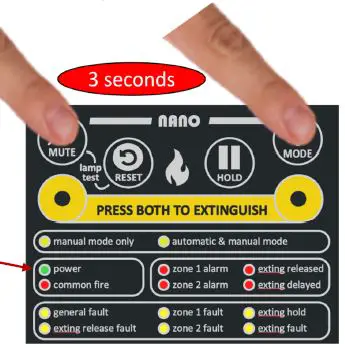
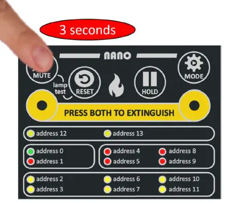
- STEP 1 MODBUS SETTINGS
Set the NANO in programming mode by pressing and holding the MODE and the MUTE
  button simultaneously for more than 3 seconds.
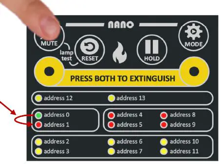
- STEP 2 INDICATION
On the front of the NANO, the green power indicator will flash rapidly. This indicates the Modbus address of this NANO in the Modbus programming mode.
- STEP 3 CHANGE ADDRESS
Press the Mute button shortly to change the address from address 0 to address 1. - STEP 4 CONFIRM CHOICE
To confirm the address, press the MUTE button for at least 3 seconds or press the Reset  button to cancel. If there is no button pressed for 60 seconds during this MODBUS address selection mode. The operation is automatically canceled.
- STEP 5 CHECK CONNECTION
To test the connection and communication,various tools are available in the market. For example, the FTDI USB-RS485-WE-1800-BT cable can be used to connect the hardware to a PC. A simple and easy-to-use test application,among others, is the Schneider Electric Modbus Tester application for Windows.
MODBUS REGISTER
All parameters are read only holding registers and can be read by an external MODBUS RTU master device via “Read hold register” commands. It is possible to read multiple registers with one command by changing the requested data length. All register contains 16 bits data. If data is requested beyond the last available register the data is cut-off at the end and the reply will have the corrected data length.
The data has the most significant byte first (MSB first) as this is the most common way to format the 16 bits register content in MODBUS RTU.
| Register | Name | Description | length |
| 40000 | Product name | Always replies with the string “NKB1310” | 20 |
| 40020 | Version | Firmware version Major revision in high byte, minor revision in lower byte | 1 |
| 40021 | Reboots | Number of reboots since first started | 1 |
| 40023 | Sounder state | External sounder state: 0 = IDLE, 1 = OPEN, 2 = SHORTED, 3 = ACTIVATED | 1 |
| 40030 | Current event state: fault exting open | 1 = Active, 0 = Not active | 1 |
| 40031 | Current event state: fault exting shorted | 1 = Active, 0 = Not active | 1 |
| 40032 | Current event state: fault firezone 1 open | 1 = Active, 0 = Not active | 1 |
| 40033 | Current event state: fault firezone 1 shorted | 1 = Active, 0 = Not active | 1 |
| 40034 | Current event state: fault firezone 2 open | 1 = Active, 0 = Not active | 1 |
| 40035 | Current event state: fault firezone 2 shorted | 1 = Active, 0 = Not active | 1 |
| 40036 | Current event state: fault sounder open | 1 = Active, 0 = Not active | 1 |
| 40037 | Current event state: fault sounder shorted | 1 = Active, 0 = Not active | 1 |
| 40038 | Current event state: fault external hold open | 1 = Active, 0 = Not active | 1 |
| 40039 | Current event state: fault external hold shorted | 1 = Active, 0 = Not active | 1 |
| 40040 | Current event state: fault external hold midrange | 1 = Active, 0 = Not active | 1 |
| 40041 | Current event state: fault external release open | 1 = Active, 0 = Not active | 1 |
| 40042 | Current event state: fault external release shorted | 1 = Active, 0 = Not active | 1 |
| 40043 | Current event state: fault external release midrange | 1 = Active, 0 = Not active | 1 |
| 40044 | Current event state: fault power disconnected | 1 = Active, 0 = Not active | 1 |
| 40045 | Current event state: external release | 1 = Active, 0 = Not active | 1 |
| 40046 | Current event state: external hold | 1 = Active, 0 = Not active | 1 |
| 40047 | Current event state: firezone0 fire | 1 = Active, 0 = Not active | 1 |
| 40048 | Current event state: firezone1 fire | 1 = Active, 0 = Not active | 1 |
| 40050 | Current event state: charged cap | 1 = Active, 0 = Not active | 1 |
| 40053 | Current event state: vehicle mode | 1 = Active, 0 = Not active | 1 |
| 40054 | Current event state: backup power mode | 1 = Active, 0 = Not active | 1 |
| 40055 | Current event state: usb power connected | 1 = Active, 0 = Not active | 1 |
| 40080 | Event count: fault exting open | Nr. Of events occurred since reboot | 1 |
| 40081 | Event count: fault exting shorted | Nr. Of events occurred since reboot | 1 |
| 40082 | Event count: fault firezone 1 open | Nr. Of events occurred since reboot | 1 |
| 40083 | Event count: fault firezone 1 shorted | Nr. Of events occurred since reboot | 1 |
| 40084 | Event count: fault firezone 2 open | Nr. Of events occurred since reboot | 1 |
| 40085 | Event count: fault firezone 2 shorted | Nr. Of events occurred since reboot | 1 |
| 40086 | Event count: fault sounder open | Nr. Of events occurred since reboot | 1 |
| 40087 | Event count: fault sounder shorted | Nr. Of events occurred since reboot | 1 |
| 40088 | Event count: fault external hold open | Nr. Of events occurred since reboot | 1 |
| 40089 | Event count: fault external hold shorted | Nr. Of events occurred since reboot | 1 |
| 40090 | Event count: fault external hold midrange | Nr. Of events occurred since reboot | 1 |
| 40091 | Event count: fault external release open | Nr. Of events occurred since reboot | 1 |
| 40092 | Event count: fault external release shorted | Nr. Of events occurred since reboot | 1 |
| 40093 | Event count: fault external release midrange | Nr. Of events occurred since reboot | 1 |
| 40094 | Event count: fault power disconnected | Nr. Of events occurred since reboot | 1 |
| 40095 | Event count: external release | Nr. Of events occurred since reboot | 1 |
| 40096 | Event count: external hold | Nr. Of events occurred since reboot | 1 |
| 40097 | Event count: firezone 1 fire | Nr. Of events occurred since reboot | 1 |
| 40098 | Event count: firezone 2 fire | Nr. Of events occurred since reboot | 1 |
| 40100 | Event count: charged cap | Nr. Of events occurred since reboot | 1 |
| 40103 | Event count: vehicle mode | 1 = Active, 0 = Not active | 1 |
| 40104 | Event count: backup power mode | 1 = Active, 0 = Not active | 1 |
| 40105 | Event count: usb power connected | 1 = Active, 0 = Not active | 1 |
| 40130 | Led state: ext release fault | 0 = off, 1 = on, 2 = blink, 3 = blink fast | 1 |
| 40131 | Led state: power | 0 = off, 1 = on, 2 = blink, 3 = blink fast | 1 |
| 40132 | Led state: manual mode | 0 = off, 1 = on, 2 = blink, 3 = blink fast | 1 |
| 40133 | Led state: zone 1 alarm | 0 = off, 1 = on, 2 = blink, 3 = blink fast | 1 |
| 40134 | Led state: zone2 alarm | 0 = off, 1 = on, 2 = blink, 3 = blink fast | 1 |
| 40135 | Led state: zone1 fault | 0 = off, 1 = on, 2 = blink, 3 = blink fast | 1 |
| 40136 | Led state: zone 2 fault | 0 = off, 1 = on, 2 = blink, 3 = blink fast | 1 |
| 40137 | Led state: general fault | 0 = off, 1 = on, 2 = blink, 3 = blink fast | 1 |
| 40138 | Led state: fire1 | 0 = off, 1 = on, 2 = blink, 3 = blink fast | 1 |
| 40139 | Led state: auto mode | 0 = off, 1 = on, 2 = blink, 3 = blink fast | 1 |
| 40140 | Led state: released | 0 = off, 1 = on, 2 = blink, 3 = blink fast | 1 |
| 40141 | Led state: delay | 0 = off, 1 = on, 2 = blink, 3 = blink fast | 1 |
| 40142 | Led state: hold | 0 = off, 1 = on, 2 = blink, 3 = blink fast | 1 |
| 40143 | Led state: exting fault | 0 = off, 1 = on, 2 = blink, 3 = blink fast | 1 |
| 40144 | Led state: sounder fault | 0 = off, 1 = on, 2 = blink, 3 = blink fast | 1 |
| 40145 | Led state: backup power | 0 = off, 1 = on, 2 = blink, 3 = blink fast | 1 |
| 40146 | Led state: ext hold fault | 0 = off, 1 = on, 2 = blink, 3 = blink fast | 1 |
| 40147 | Led state: fire2 | 0 = off, 1 = on, 2 = blink, 3 = blink fast | 1 |
| 40148 | Led state: fire3 | 0 = off, 1 = on, 2 = blink, 3 = blink fast | 1 |
| 40150 | VFC state: Fire | 1 = Active, 0 = Not active | 1 |
| 40151 | VFC state: Fault | 1 = Active, 0 = Not active | 1 |
| 40152 | VFC state: Fan | 1 = Active, 0 = Not active | 1 |
| 40153 | VFC state: Extinguish | 1 = Active, 0 = Not active | 1 |
| 40160 | Button state: Reset | 0 = not pushed, 1 = pushed, 2 = pushed long, 3 = pushed longer | 1 |
| 40161 | Button state: Hold | 0 = not pushed, 1 = pushed, 2 = pushed long, 3 = pushed longer | 1 |
| 40162 | Button state: Mode | 0 = not pushed, 1 = pushed, 2 = pushed long, 3 = pushed longer | 1 |
| 40163 | Button state: Mute | 0 = not pushed, 1 = pushed, 2 = pushed long, 3 = pushed longer | 1 |
| 40164 | Button state: Extinguish | 0 = not pushed, 1 = pushed, 2 = pushed long, 3 = pushed longer | 1 |
| 40170 | Button pushed count: Reset | Nr. Of events occurred since reboot | 1 |
| 40171 | Button pushed count: Hold | Nr. Of events occurred since reboot | 1 |
| 40172 | Button pushed count: Mode | Nr. Of events occurred since reboot | 1 |
| 40173 | Button pushed count: Mute | Nr. Of events occurred since reboot | 1 |
| 40174 | Button pushed count: Extinguish | Nr. Of events occurred since reboot | 1 |
| 40180 | Button pushed long count: Reset | Nr. Of events occurred since reboot | 1 |
| 40181 | Button pushed long count: Hold | Nr. Of events occurred since reboot | 1 |
| 40182 | Button pushed long count: Mode | Nr. Of events occurred since reboot | 1 |
| 40183 | Button pushed long count: Mute | Nr. Of events occurred since reboot | 1 |
| 40184 | Button pushed long count: Extinguish | Nr. Of events occurred since reboot | 1 |
| 40190 | Button pushed longer count: Reset | Nr. Of events occurred since reboot | 1 |
| 40191 | Button pushed longer count: Hold | Nr. Of events occurred since reboot | 1 |
| 40192 | Button pushed longer count: Mode | Nr. Of events occurred since reboot | 1 |
| 40193 | Button pushed longer count: Mute | Nr. Of events occurred since reboot | 1 |
| 40194 | Button pushed longer count: Extinguish | Nr. Of events occurred since reboot | 1 |
| 40220 | Main voltage | units: mV | 1 |
| 40221 | Internal voltage | units: mV | 1 |
| 40222 | Backup power voltage | units: mV | 1 |
| 40224 | Extinguish power capacitor voltage | units: mV | 1 |
| 40225 | Board temperature | units: degrees Celcius * 10 | 1 |
| 40226 | Extinguish sense voltage | units: mV | 1 |
| 40227 | Sounder port voltage positive pole | units: mV | 1 |
| 40228 | Sounder port voltage negative pole | units: mV | 1 |
| 40229 | Firezone 1 Voltage | units: mV | 1 |
| 40230 | Firezone 2 Voltage | units: mV | 1 |
| 40231 | Firezone 1 Current | units: uA | 1 |
| 40232 | Firezone 2 Current | units: uA | 1 |
| 40233 | Firezone 1 Resistance | units: Ohm | 1 |
| 40234 | Firezone 2 Resistance | units: Ohm | 1 |
| 40235 | External release button resistance | units: Ohm | 1 |
| 40236 | External hold button resistance | units: Ohm | 1 |
| 40237 | Vehicle input Voltage | units: mV | 1 |
| 40250 | Reading above this register will return no answer |
Modbus user manual
NANO-NL
November 1, 2022
version


