
![]() Code No. 08160054
Code No. 08160054
Rev. 1 (11/21)
INSTALLATION INSTRUCTIONS FOR
TRUFLUSH ELECTRONIC DUAL FLUSH FLUSHOMETERS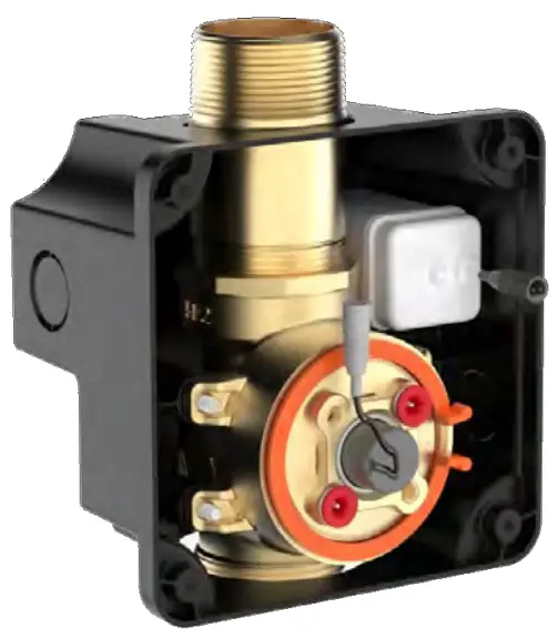 TruFlush Model: TRF 8036
LIMITED WARRANTY
Unless otherwise noted, Sloan India Pvt. Ltd warrants this product, manufactured and sold for commercial or industrial uses, to be free from defects in material and workmanship for a period of five (5) years and 1 Year- All Electronic & battery not covered in warranty from date of first purchase. During this period, Sloan India Pvt. Ltd will, at its option, repair, replace, or refund the purchase price of any product which fails to conform with this warranty under normal use and service. This shall be the sole and exclusive remedy under this warranty. Products must be returned to Sloan India Pvt. Ltd, at customer’s cost. No claims will be allowed for labor, transportation or other costs. This warranty extends only to persons or organizations who purchase Sloan India Pvt. Ltd products directly from Sloan India Pvt. Ltd for purpose of resale. This warranty does not cover the life of the batteries.
THERE ARE NO WARRANTIES WHICH EXTEND BEYOND THE DESCRIPTION ON THE FACE HEREOF. IN NO EVENT IS SLOAN INDIA PVT. LTD RESPONSIBLE FOR ANY CONSEQUENTIAL DAMAGES OF ANY MEASURE WHATSOEVER.
PRIOR TO INSTALLATION
This valve is designed for new construction or where there is easily accessed plumbing for the fixture and the valve.
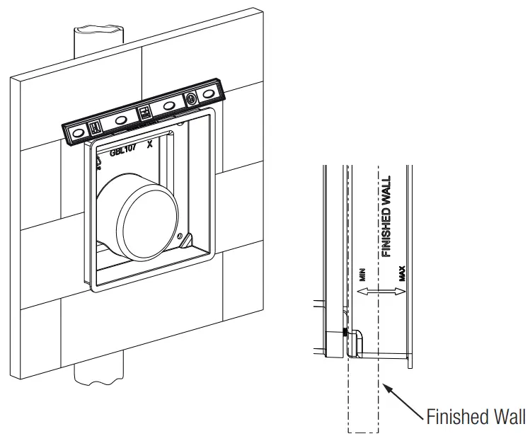
This valve is designed for minimum six inch (152 mm) wall space depth. Distance from center of the valve (inlet or outlet pipe) to the finished surface of the wall can vary from 2”-3” (51-76 mm).
Wall plate opening must be of 5.6” x 5.6” (142 x 142 mm). Mud plate is provided and must accompany valve for proper installation. Mud plate is removed after wall is finished.
TOOLS REQUIRED FOR INSTALLATION

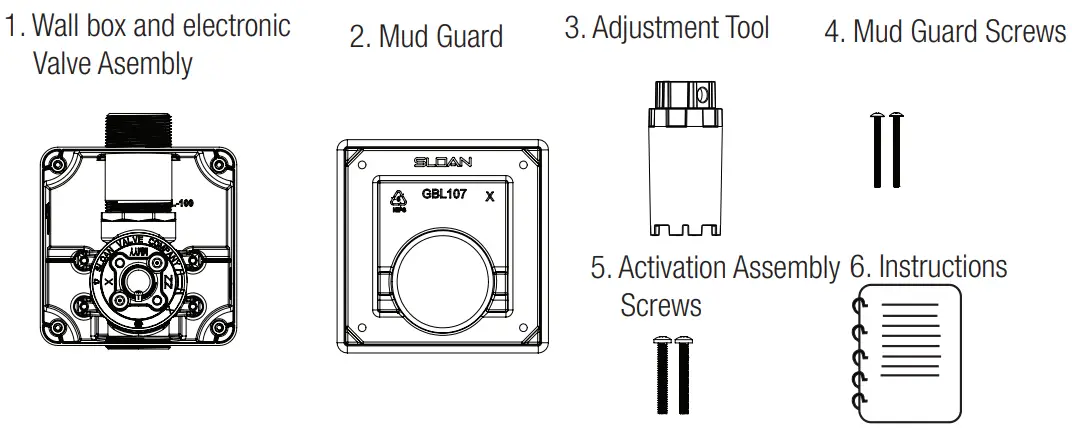
ITEMS INCLUDED WITH THE PRODUCT
VALVE BOX
- Wall Box and Electronic Valve Assembly
- Mud Guard
- Adjustment Tool
- (2) #8-32 x 2” screws to secure mud guard
- (2) 1/4”-20 x 2” screws to remove activation assembly
- Installation instructions ITEM #1: WALL BOX
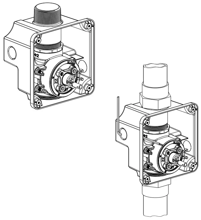
ROUGH-IN
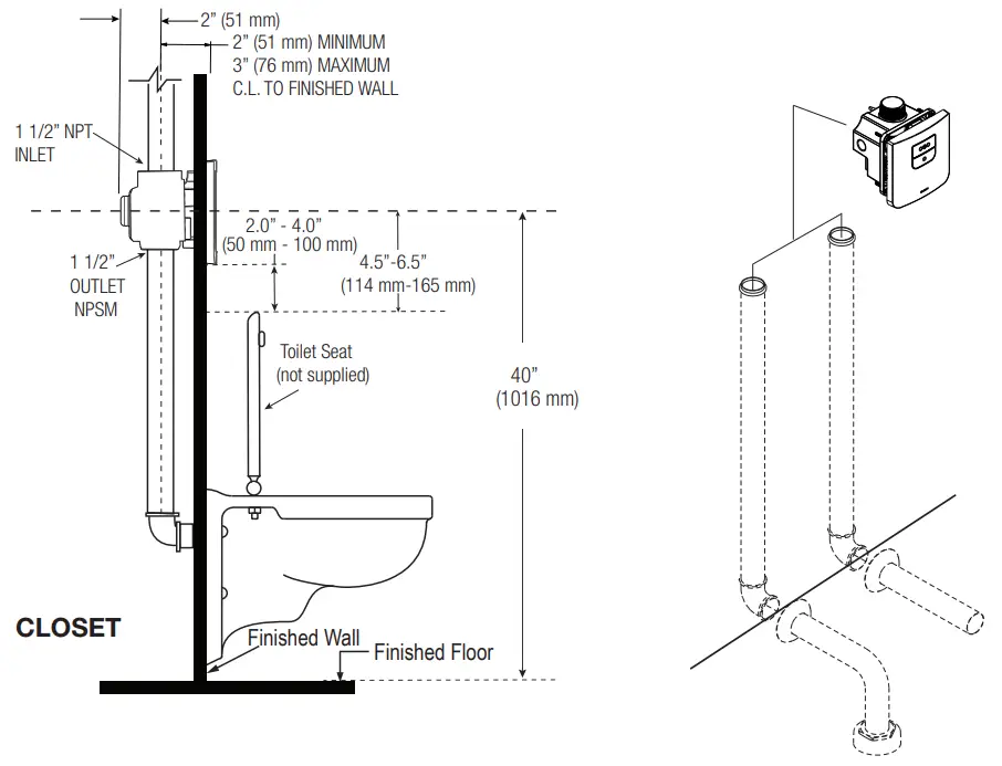
NOTE : Flush Connections shown in dotted lines not included.
!!! IMPORTANT !!!
SLOAN’S FLUSHOMETERS ARE DESIGNED TO OPERATE WITH 20 TO 80 PSI (138 TO 552 KPA) OF WATER PRESSURE. THE MINIMUM PRESSURE REQUIRED TO THE VALVE IS DETERMINED BY THE TYPE OF FIXTURE SELECTED. CONSULT FIXTURE MANUFACTURER FOR MINIMUM PRESSURE REQUIREMENTS. MOST HIGH EFFICIENCY WATER CLOSETS REQUIRE A MINIMUM FLOWING PRESSURE OF 25 PSI (172 KPA). MANY BUILDING CODES AND THE ASME A112.19.2 FIXTURE STANDARD LIST MAXIMUM STATIC WATER PRESSURE AS 80 PSI (552 KPA).
!!! IMPORTANT !!!
WITH THE EXCEPTION OF INLET, DO NOT USE PIPE SEALANT. DO NOT USE PLUMBING GREASE ON VALVE COMPONENTS OR COUPLINGS!
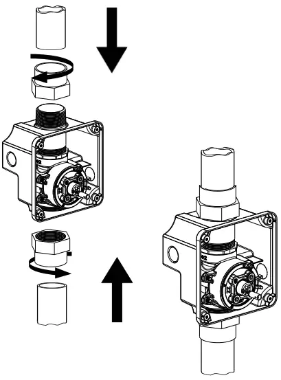
CONNECT FLUSHOMETER
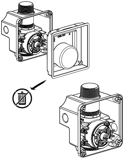
- Remove the mudguard and save it for later use- DO NOT DISCARD.

- Connect the inlet pipe to top (“IN”) and fixture flush connection to bottom (“OUT”) of flushometer.

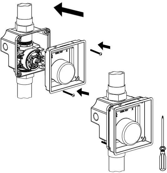
- Reinstall mud guard to valve. Use the mudguard screws (supplied).
 !!! IMPORTANT !!!
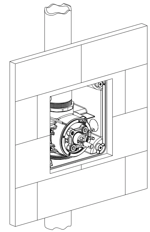
MAKE SURE SUPPLY LINES ARE FLUSHED OUT. DEBRIS CAN DAMAGE THE VALVE OR CAUSE VALVE TO MALFUNCTION. DO NOT CONTINUE THE INSTALLATION UNTIL SUPPLY LINES ARE CLEAR. - Use the Water Level to make sure the Valve is level. Finish the wall. Use marks on mudguard to make sure finished wall is in between 2” (51 mm) and 3” (76 mm) from centerline of the inlet pipe.

- Only Remove the mudguard when installing Wall Plate. For more information Refer Wall Plate Installation Manual (08160044).
Note: Removing the Mudguard beforehand might result in damge to the solenoid from debris.
CONNECT FLUSHOMETER (HARDWIRE CONNECTION)
- Remove one of the knockout caps and route the transformer wire trough it inside wall box.
NOTE: Use a conduit pipe to protect the transformer wire from damage during installation.
- Finish the wall as instructed above.

!!! IMPORTANT !!!
TRANSFORMER NOT PROVIDED. IT IS VERY IMPORTANT THAT THE OUTPUT VOLTAGE OF THE TRANSFORMER MUST BE 6VAC FOR THE UNIT TO FUNCTION PROPERLY. SLOAN EL-386 OR EL-451 IS RECOMMENDED (120 VAC/6VAC) OR ELG-220 (220VAC/6VAC).
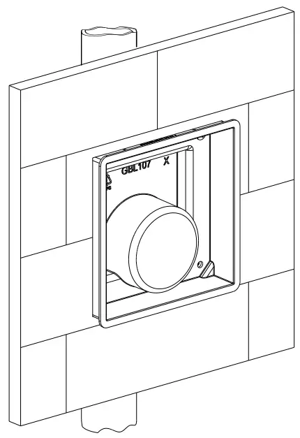
INSTALL WALL PLATE ASSEMBLY
Refer Wall Plate Installation Manual (08160044).
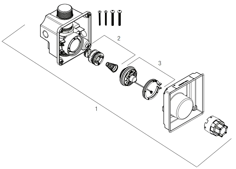
PARTS LIST
| Item No. | Description |
| 1 | Valve Assembly Less Plate |
| 2 | Piston Assembly |
| 3 | Activation Assembly |
Wall Plate Assembly Installation Manual (08160044), available on www.sloan.in
For complete listing of items available for repair, please consult Maintenance and Repair Guide. available on www.sloan.in
Code No. 08160054
Rev. 1 (11/21)
Manufactured by Sloan India Pvt. Ltd, patents pending.
© 2021 SLOAN
SLOAN INDIA PRIVATE LIMITED
344, PHASE-II UDYOG VIHAR, GURGAON 122015 Phone: (+91) 124-6013300/33
Toll Free: 1800.123.3080
[email protected] | sloan.in
copyright © 2021 Sloan All rights reserved


