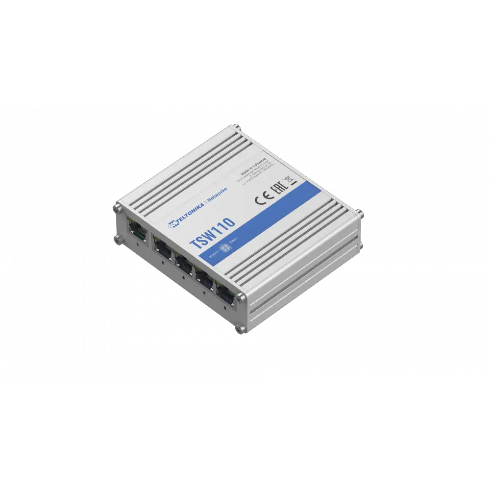
TELTONIKA TSW110 Quick Start Guide v1.1
![]()

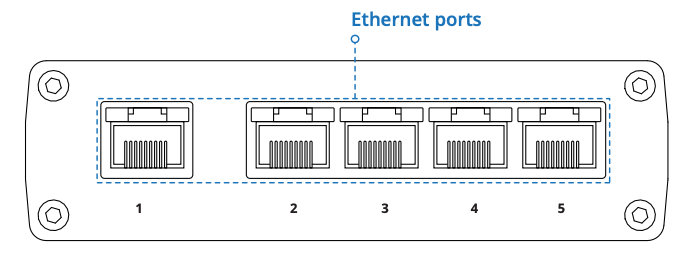
FRONT VIEW
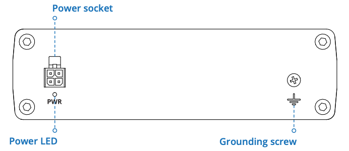
BACK VIEW
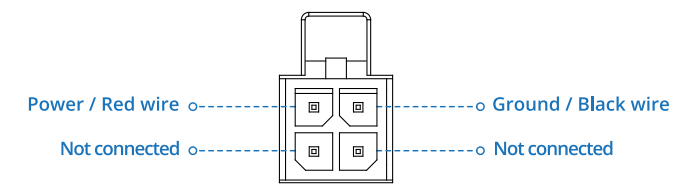
POWER SOCKET PINOUT
RJ45 LED MEANING

TECHNICAL INFORMATION
| Technical specifications | |
| Input voltage range | 9 – 30 VDC |
| Max power consumption | <1.8 W |
| Bundled accessories specifications* | |
| Power adapter | Input: 0.4 A @100-240 VAC, Output: 9 VDC, 1 A, 4 pin plug |
* Order code dependent.
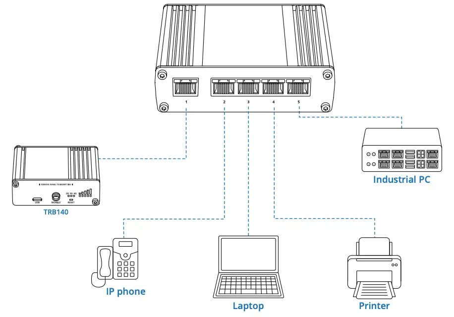
HARDWARE INSTALLATION
- Connect your main internet router/modem to TSW110 LAN port number 1.
- Connect end devices (ex. Industrial PC, printers, IP phones, laptops) to TSW110 2 to 5 port.
- Connect 4 pin power plug to TSW110 to power up switch.
SAFETY INFORMATION
TSW110 switch must be used in compliance with any and all applicable national and international laws and with any special restrictions regulating the utilization of the communication module in prescribed applications and environments.
Hereby, TELTONIKA NETWORKS declares that this TSW110 is in compliance with the essential requirements and other relevant provisions of Directive 2014/30/EU and 2014/35/EU.
The full text of the EU declaration of conformity is available at the following Internet address: https://wiki.teltonika-networks.com/view/TSW110_CE
Instruction Manual: Connect the power adapter to turn on the device. More information on https://wiki.teltonika-networks.com/
![]()
This sign means that all used electronic and electric equipment should not be mixed with general household waste.
![]()
This sign means that product meets the requirements of the applicable EU directives.
www.teltonika-networks.com © 2021 Teltonika Networks


