![]()
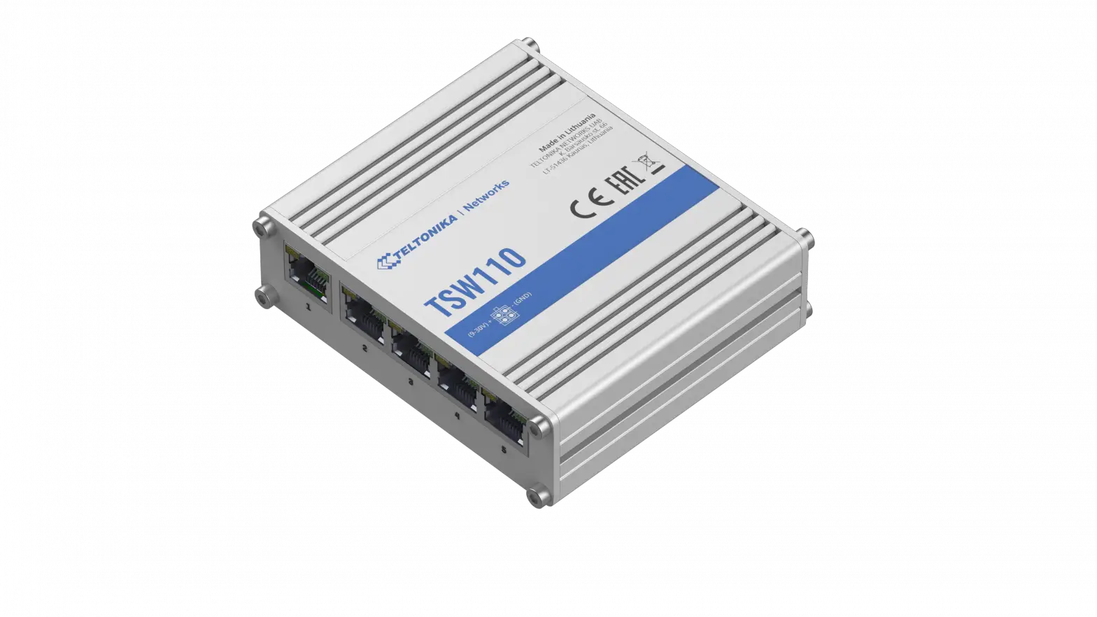
TSW110
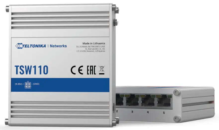
HARDWARE
FRONT VIEW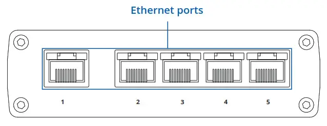 BACK VIEW
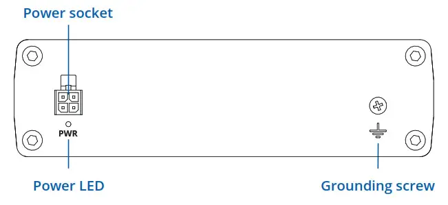
RJ45 LED MEANING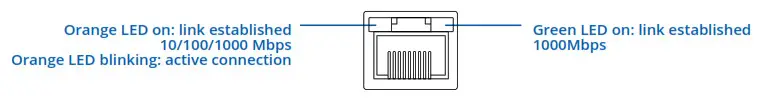
POWER SOCKET PINOUT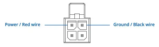
FEATURES
| ETHERNET | |
| LAN | 5 x LAN port, 10/100/1000 Mbps, compliance with IEEE 802.3, IEEE 802.3u, 802.3az standards, supports auto MDI/MDIX crossover |
| PERFORMANCE SPECIFICATIONS | |
| Bandwidth (Non-blocking) | 10 Gbps |
| Packet buffer | 128 KB |
| Jumbo frame support | 9216 bytes |
| MAC address table size | 2K entries |
| Connector | 4 pin industrial DC power socket |
| Input voltage range | 9 – 30 VDC, reverse polarity protection, voltage surge/transient protection |
| PoE (passive) | Passive PoE. Possibility to power up through LAN port, not compatible with IEEE802.3af, 802.3at and 802.3bt standards |
| Power consumption (idle/max) | < 0.4 W/ <1.8 W |
| PHYSICAL INTERFACES (PORTS, LEDS) | |
| Ethernet | 5 x RJ45 ports, 10/100/1000 Mbps |
| Status LEDs | 1 x Power LED, 10 x LAN status LED’s |
| Power | 1 x 4 pin DC connector |
| Ground | 1 x Grounding screw |
| PHYSICAL SPECIFICATION | |
| Casing material | Full aluminum housing |
| Dimensions (W x H x D) | 100 x 30 x 85 mm |
| Weight | 227 g |
| Mounting options | DIN rail or wall mounting (additional kit needed), flat surface placement |
| OPERATING ENVIRONMENT | |
| Operating temperature | -40 C to 75 C |
| Operating humidity | 10 % to 90 % non-condensing |
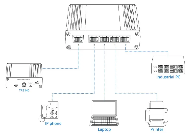
HARDWARE INSTALLATION
- Connect your main internet router/modem to TSW110 LAN port number 1.
- Connect end devices (ex. Industrial PC, printers, IP phones, laptops) to TSW110 2 to 5 port.
- Connect 4 pin power plug to TSW110 to power up switch.

TECHNICAL INFORMATION
Technical specifications | |
| Input voltage range | 9 – 30 VDC |
| Max power consumption | <1.8 W |
Bundled accessories specifications* | |
| Power adapter | Input: 0.4 A @100-240 VAC, Output: 9 VDC, 1 A, 4 pin plug |
WHAT’S IN THE BOX?
STANDARD PACKAGE CONTAINS
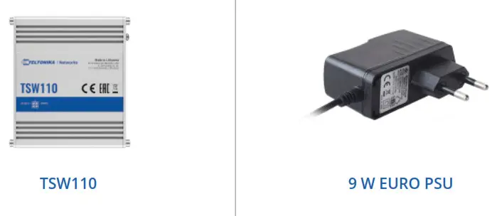
- TSW110
- 9 W Euro PSU
- QSG (Quick Start Guide)
- Packaging box


STANDARD ORDER CODES
| PRODUCT CODE | HS CODE | HTS CODE | PACKAGE CONTAINS |
| TSW110000000 | 851762 | 8517.62.00 | Standard package |
MOUNTING OPTIONS
DIN RAIL KIT
| Parameter | Value |
| Mounting standard | 35mm DIN Rail |
| Material | Low carbon steel |
| Weight | 57g |
| Screws included | Philips Pan Head screw #6-32×3/16, 2pcs |
| Dimensions | 82 mm x 46 mm x 20 mm |
| RoHS Compliant | V |
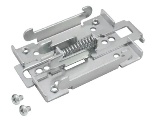 DIN RAIL KIT
- DIN Rail adapter
- Philips Pan Head screw #6-32×3/16, 2pcs for RUT2xx/RUT9xx
| ORDER CODE | PRODUCT CODE | HS CODE | HTS CODE |
| 088-00267 | PR5MEC00 | 73269098 | 7326.90.98 |
For more information on all available packaging options please contact us directly.
COMPACT DIN RAIL KIT
| Parameter | Value |
| Mounting standard | 35mm DIN Rail |
| Material | ABS + PC plastic |
| Weight | 6.5 g |
| Screws included | Philips Pan Head screw #6-32×3/16, 2pcs |
| Dimensions | 70 mm x 25 mm x 14,5 mm |
| RoHS Compliant | V |

DIN RAIL KIT
- Compact plastic DIN Rail adapter (70x25x14,5mm)
- Philips Pan Head screw #6-32×3/16, 2pcs
| ORDER CODE | PRODUCT CODE | HS CODE | HTS CODE |
| 088-00270 | PR5MEC11 | 73269098 | 7326.90.98 |
For more information on all available packaging options please contact us directly.
SURFACE MOUNTING KIT
| Parameter | Value |
| Mounting standard | Flat surface mount |
| Material | ABS + PC plastic |
| Weight | 2×5 g |
| Screws included | Philips Pan Head screw #6-32×3/16, 2pcs |
| Dimensions | 25 mm x 48 mm x 7.5 mm |
| RoHS Compliant | V |
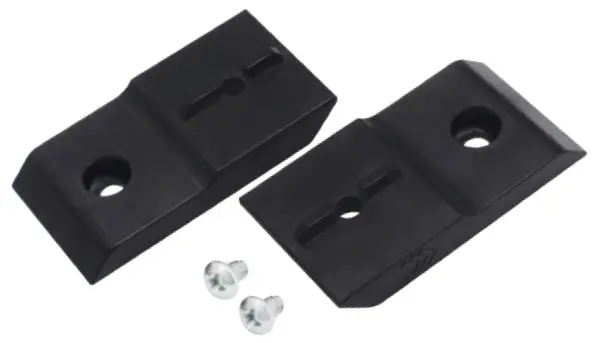
DIN RAIL KIT
- Surface mounting kit
- Philips Pan Head screw #6-32×3/16, 2pcs
| ORDER CODE | PRODUCT CODE | HS CODE | HTS CODE |
| 088-00281 | PR5MEC12 | 73269098 | 7326.90.98 |
For more information on all available packaging options – please contact us directly.
TSW110 SPATIAL MEASUREMENTS & WEIGHT
MAIN MEASUREMENTS
W x H x D dimensions for TSW110 :
Device housing* : 100 x 30 x 85
Box : 173 x 71 x 148
*Housing measurements are presented without antenna connectors and screws; for measurements of other device elements look to the sections below.
TOP VIEW
The figure below depicts the measurements of TSW110 and its components as seen from the top: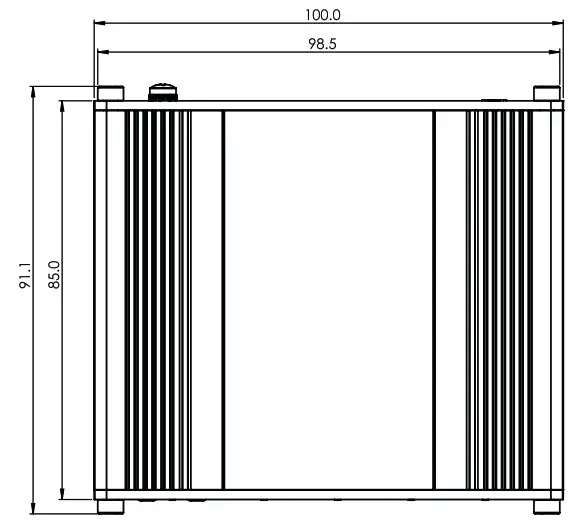
RIGHT VIEW
The figure below depicts the measurements of TSW110 and its components as seen from the right side: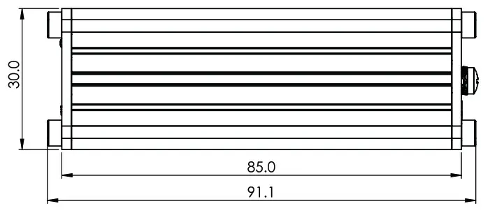 FRONT VIEW
The figure below depicts the measurements of TSW110 and its components as seen from the front panel side: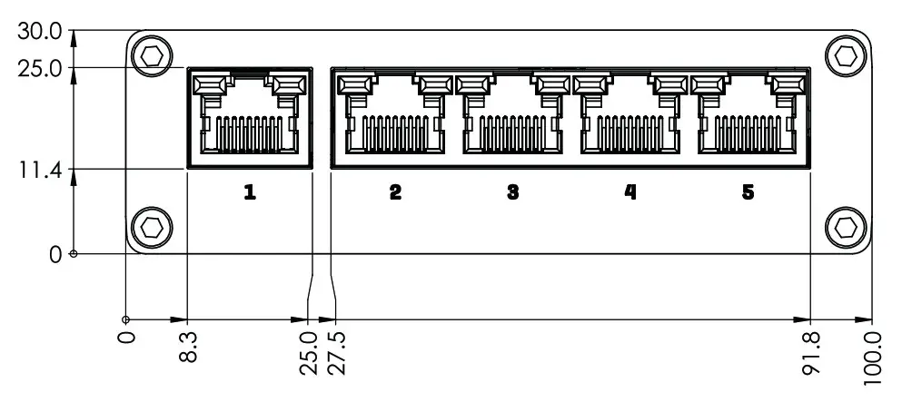
REAR VIEW
The figure below depicts the measurements of TSW110 and its components as seen from the back panel side: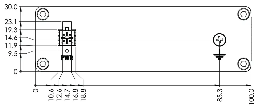
MOUNTING SPACE REQUIREMENTS
The figure below depicts an approximation of the device’s dimensions when cables and antennas are attached: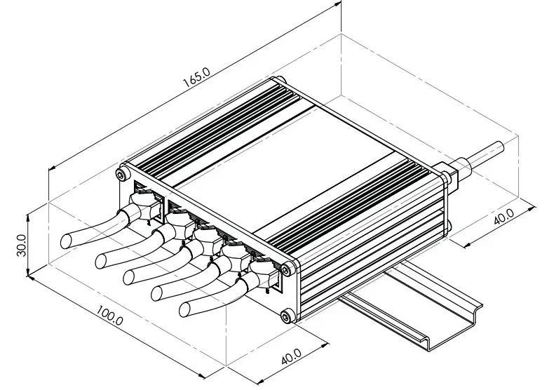
DIN RAIL
The scheme below depicts protrusion measurements of an attached DIN Rail: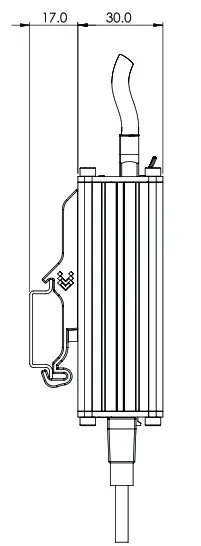
Copyright © 2021, TELTONIKA NETWORKS. Specifications and information given in this document are subject to change by TELTONIKA NETWORKS without prior notice.


