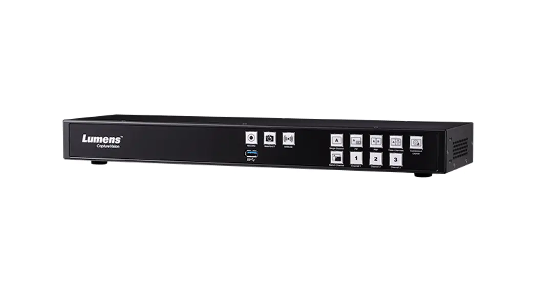
![]() LC100 Installation Guide
LC100 Installation Guide
Introduction of Product Functions
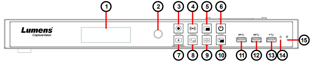
1.1 Front View
1.2 Back View
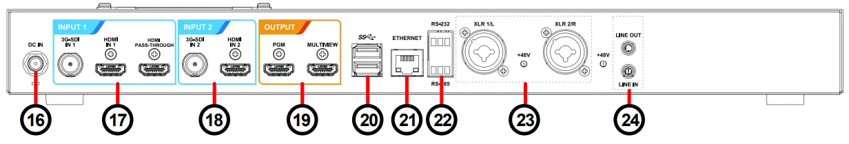
1.3 Function Descriptions
| No. | Item | Function Descriptions | No. | Item | Function Descriptions |
| 1. | LCM | Display Menu and Information | 16 | DC IN 12V | DC 12 V power connector |
| 2. | Knob | LCM knob | 17 | Input1 | • HDMI Input 1 • 3G-SDI Input 1 • HDMI Passthrough |
| 3 | Record | Start/Stop recording | |||
| 4 | Stream | On/Off image streaming | 18 | Input2 | • HDMI Input • 3G-SDI Inp 2 |
| 5 | Scene | Switch templates | 19 | Output | • PGM: Main screen output, display the recording or streaming screen and layout • Multiview: Operation interface output; display the settings menu and image management |
| 6 | Power | On/Off the device power | |||
| 7 | Single Channel | Display a single-channel screen | |||
| 8 | PIP | Switch to PIP (picture in picture) | |||
| 9 | PBP | Switch to PBP (picture by picture) | 20 | USB3.0 port | Supports the following devices: • USB video/audio devices • External storage disk • LCKeyboard/mouse -RCO1 (optional) controller |
| 10 | SWAP | Switch signal channels | |||
| 11 | USB3.0 port | for external storage disk | |||
| 12 | USB3.0 port | for external storage disk | |||
| 13 | USB2.0 port | Can connect to keyboard/mouse device operation menu | 21 | Ethernet | Connect to LAN |
| 14 | Factory Reset | Reset all configurations to factory default settings | 22 | RS-232/ RS-485 port | Connect to AV control equipment |
| 15 | Restart | Reboot the machine | 23 | XLR audio in | Connect to a microphone or audio mixer |
| 24 | Line In/ Out | Audio In/Out |
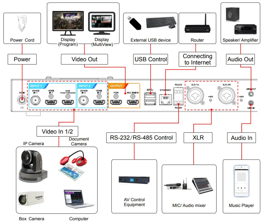
Product connection diagram
Precautions Prior to Use
3.1 Lumens strongly recommends the use of a hard drive (not supplied) for recording video and audio.
3.2 LC100 supports 2.5″/3.5″ SATA hard drives.
3.3 If no hard drive is installed, use a USB disk for external storage.
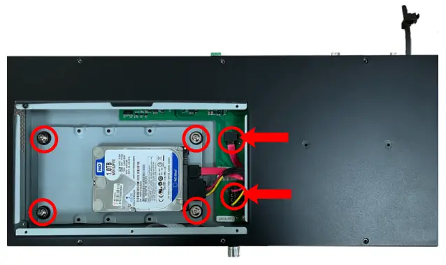
4.4 Fasten the hard disk to the metal plate with the provided screws (4 pcs).
A. 2.5″ SATA Hard Drive holes
B. 3.5″ SATA Hard Drive holes
* Do not over-tighten the screws to avoid damage to the hard drive. Only use the screws provided.
Hard drive installation steps
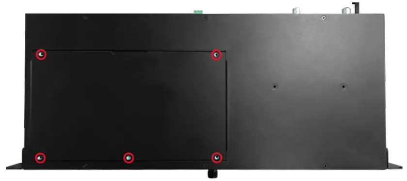
4.1 Remove the screws (5 pcs) on the top cover.
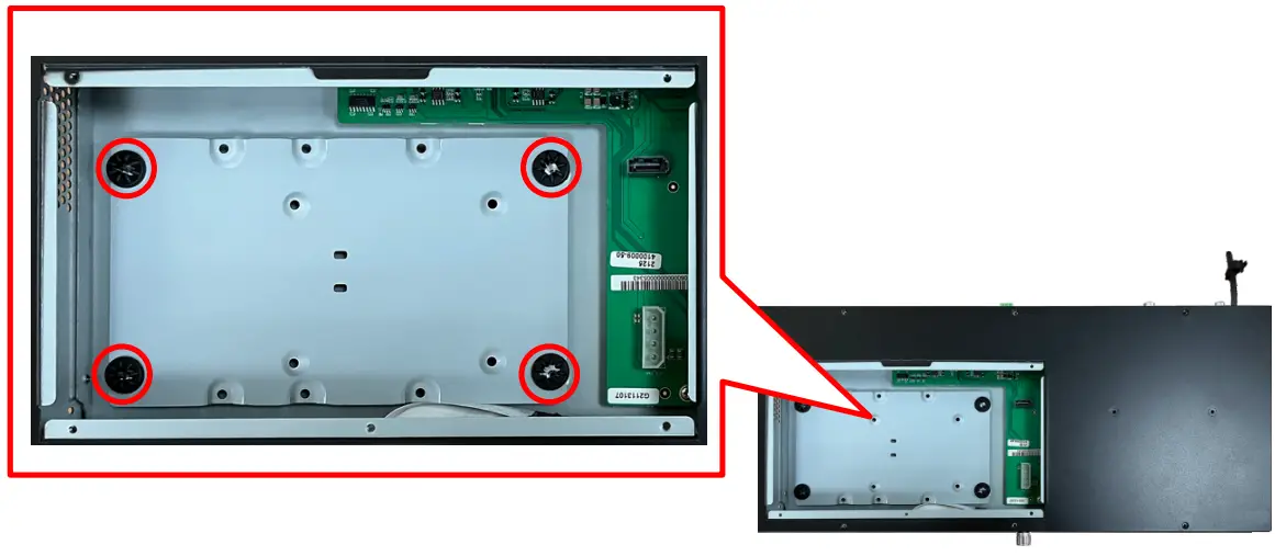
4.2 Loosen the following screws.
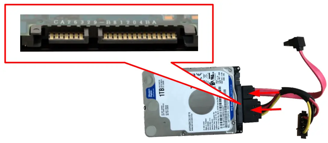
4.3 Attach your hard drive to the connection cable.
* Please make sure the port and the L-shaped slot of the cable are aligned before insertion. Do not force the connection to avoid damage to the port.
4.4 Fasten the hard disk to the metal plate with the provided screws (4 pcs).
A. 2.5″ SATA Hard Drive holes
B. 3.5″ SATA Hard Drive holes
* Do not over-tighten the screws to avoid damage to the hard drive. Only use the screws provided.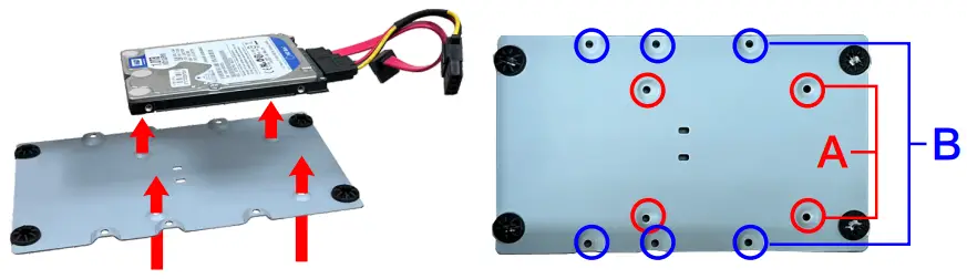
4.5 Lock the hard drive mounting plate in place and insert the connection cable.
4.6 Close the top cover to complete the installation.
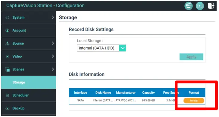
4.7 Hard drive setting
After installation, you need to log in to the web page and click Information to format the drive.
Storage Setting > Hard Disk
*Formatting the drive will erase all existing data on the disk
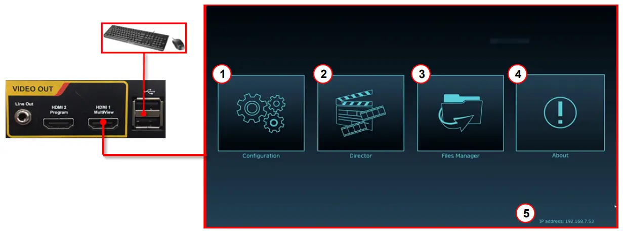
Connect the HDMI1 MultiView output to a monitor to display the real-time operation menu
| No. | Item | Function Descriptions |
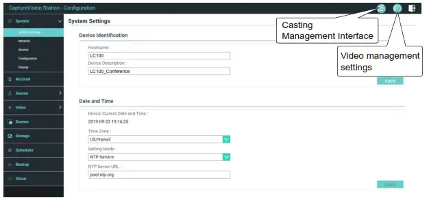
| 1 |  Configuration Configuration | Configure the network settings and recording/streaming quality |
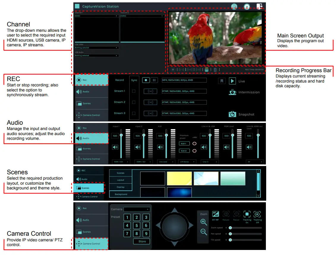
| 2 |  Director Director | Creative control of video and audio inputs, and audio feeds. Control recording and streaming and network video cameras |
| 3 |  File Management File Management | Transfer, upload, download, delete, and playback video files |
| 4 |  About About | Display the current LC100 firmware version |
| 5 | Device IP | Displays the device’s network IP address. |
Web Interface
6.1 Confirm the IP address of the device
Connect the LC100 to a router. Note the IP address of the device (visible in the lower right corner of the HDMI MultiView output screen).
6.2 Input the device,s IP address into the web browser, e.g. 192.168.100.100.

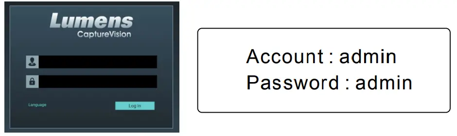
6.3 Please enter your account/password to log in.
Web Interface
Thru the web interface users can access the File Manager, the MultiView interface, and system settings.
Director Tab
Follow these steps to access the Director Tab
- On the MultiView interface, select Director

- Log in to the web page by entering the online Director Casting Account /Password (default setting: director/director)
www.MyLumens.com
Copyright © Lumens Digital Optics Inc. All rights reserved.


