
TRANSGO 45-01 1965-66 C4 Performance Valve Body Kit

Clean Crisp Automatic Shifts
Remember “Green Dot” Transmissions start in 2nd & Shift to 3rd when the gear selector is one click back from Neutral.
Burnouts: In water or bleach box: Break it loose in 1st/2nd, then up-shift to 3rd. THESE ARE THE TRANSMISSION RATIOS: “1st” 2.46 “2nd” 1.46 “3rd” 1.00 Overall ratios: Multiply axle ratio x trans ratio. [Example 3.73 x 2.46 = 9.25 1st]
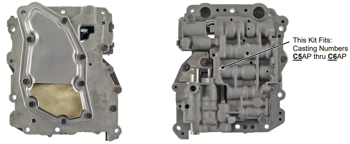
Use this page to assemble VB Channel Casting.
New Gasket provided ALWAYS goes between channel casting and separator plate!
Use Gasket Provided
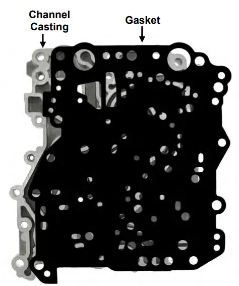
- Install Channel Casting Gasket provided onto clean empty Channel Casting. There are no check-balls used in this VB at all!

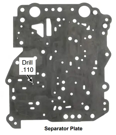
- Enlarge separator plate hole with .110 drill provided before final assembly of channel casting.

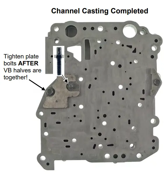
- Install hold-down plates and bolts but do NOT tighten bolts until entire VB is assembled.
Main VB
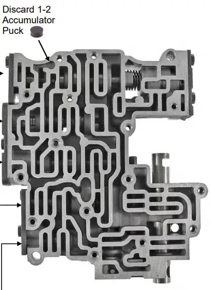
- Remove and Discard 1-2 Accumulator Puck.
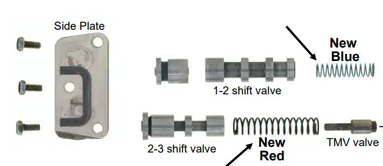
- Remove and discard the original 1-2 innerspring. Install New Blue spring.

- Remove and discard the original 2-3 springs. Install NEW RED spring.

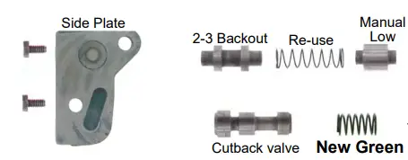
- Install New Green Spring for Cutback valve.
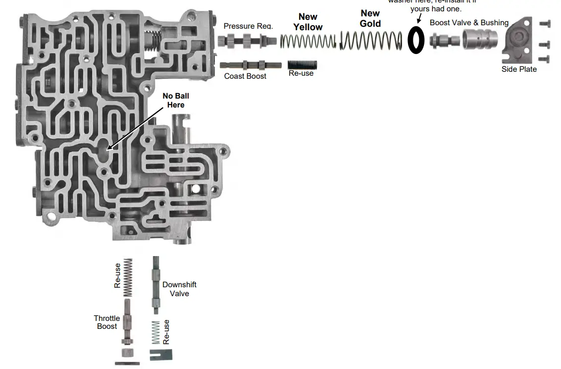
- Install Gold Outer Spring and Yellow Inner Spring on Pressure Reg.
Final Assembly
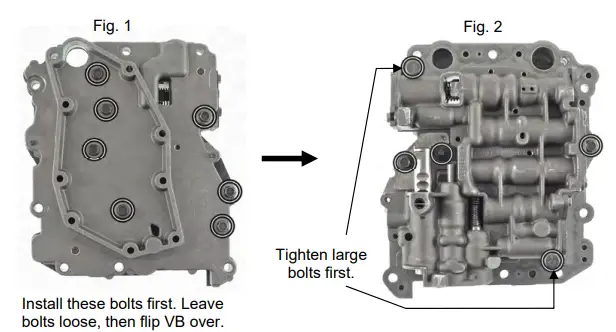
Lay completed Channel onto Completed VB (Fig. 1) and Install 7 short bolts but do not tighten. Flip VB over and install 2 Large bolts as shown in fig 2. Tighten large bolts first and then 3 small channel plate bolts. Flip VB back over and tighten 7 bolts as shown in fig 1. Install filter and tighten filter bolts, then tighten side plate bolts last. Tighten small bolts with a spin-tight or nut-driver. 2 Large bolts and VB to Case bolts Snug with a short wrench.
Important Information
Trans MUST have a vacuum modulator hookup. Always connect the manifold vacuum to the modulator. Even a Low vacuum is better than none! Kick-down linkage is adjusted so you can get a 3-2 downshift comfortably with the accelerator pedal near the floorModulator Adjustment: Adjustable modulators have a screw visible when you remove the vacuum hose. No more than 3 turns in either direction from the factory starting point. Better to be a little early than late! Saves gas, has longer trans life, and has better performance overall. Make 1 change and road test.
For earlier shifts: Turn the screw counterclockwise 1 turn at a time or you can also use a shorter modulator pin. For later shifts: Turn clockwise 1 turn at a time, or you can use a longer modulator pin.
If trans has a brief bind-up on 1-2 shift:
Back off the rear band adjustment one additional turn.
Trans Operation:
P R N D2 D1 L
- D2 Starts on the 2nd. Shifts to 3rd Kicks-down to 2nd but not to first.
- D1 Starts in 1st and shifts 1-2 & 2-3 Kicks-down to 2nd or 1st-speed dependent.
- L Starts off and stays in Low [1st]
Adjusting Bands: Apply a little sealant to the back side of the locknut to prevent leaks. Hold adjuster while tightening locknut after adjusting Bands.


