 110-100-T AirLite Sample Pump with Timer
Instruction Manual
863 Valley View Road, Eighty Four, PA 15330 USA
• 724-941-9701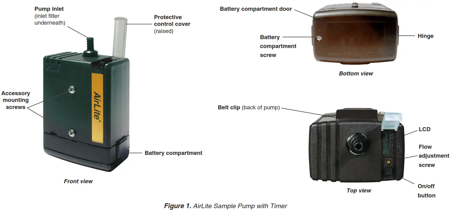
Introduction
Description
The AirLite Sample Pump with Timer (Figure 1) provides 5 to 3000 ml/min flows and is suitable for abatement, indoor air sampling, and emergency response in non-hazardous locations.
Checking Pump/Kit Contents
Use the table below to verify that you received all items associated with the Cat. No. ordered. If you are missing items, contact SKC at 800-752-8472 (the U.S. only) or 724-941-9701.
| If You Ordered Cat. No. | Your Package Should Contain |
| 110-100-T | AirLite Sample Pump with Timer only, with three AA alkaline batteries and screwdriver set |
| 110-100-TK5 | High Flow Sample Pump Kit includes 5 pumps as described above and filter cassette holders, in a Pelican case |
| 110-100-TK5D | High/Low Flow Sample Pump Kit includes 5 pumps as described above, filter cassette holders, All-in-One adjustable tube holders, and Type A protective tube covers, in a Pelican case |
Required Equipment
- 1/4-inch ID tubing
- Low flow accessories if sampling at 5 to 500 ml/min. See Accessories.
Getting Started
Insert/Replace the Batteries
The AirLite with Timer is powered by three standard AA alkaline batteries located in a compartment at the bottom of the pump (Figure 1). To insert new or replace existing batteries: 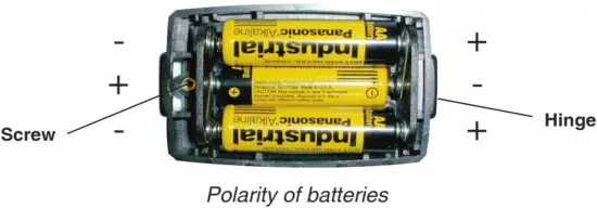
- Use a slotted screwdriver to loosen the screw on the bottom of the case (Figure 1).
- Open and remove the compartment door.
- If replacing existing batteries, remove them. Insert new batteries.
 Note the polarity of the batteries. See right.
 - With the new batteries in place, insert the hinge (Figure 1) on the compartment door under the lip of the case, close the door, and
tighten the screw until secure.
Notes and Cautions
- Do not operate AirLite with Timer in hazardous or explosive locations. AirLite with Timer is designed for applications that do not require intrinsic safety.
- Failure to follow warnings or cautions voids any warranty.
- For a maximum run time, insert new batteries in the pump before each sampling period. If using rechargeable AA 1.2-volt NiMH batteries, expect approximately half the run time stated for disposable batteries.
- To prevent corrosion of battery terminals, remove batteries when AirLite with Timer will not be used for an extended time.
- Increases in back pressure in sampling conditions due to buildup on the filter can decrease battery life.
Operation
High Flow Applications (1000 to 3000 ml/min)
Set/Calibrate Flow Rate
![]() Do not operate the pump in hazardous or explosive locations. AirLite with Timer is designed for applications that do not require intrinsic safety.
Do not operate the pump in hazardous or explosive locations. AirLite with Timer is designed for applications that do not require intrinsic safety.
- Allow the pump to equilibrate after moving it from one temperature extreme to another.
- Turn on the pump using the on/off button (Figure 1) and run for 5 minutes before calibrating. Leave the pump running.
- Prepare the calibrator. See calibrator instructions.
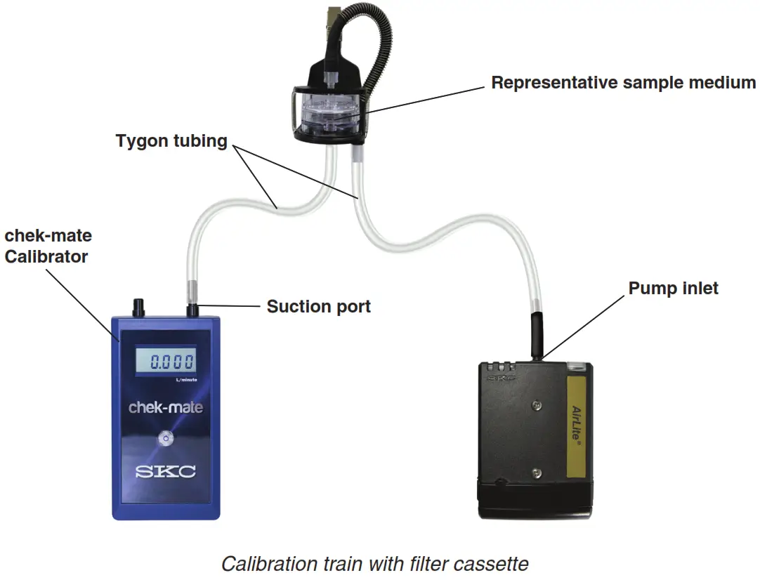
- Set up a calibration train (see below): Using flexible tubing, connect the calibrator outlet (suction port) to the representative sample medium inlet. Using 1/4-inch ID tubing, connect the representative sampling medium outlet to the pump inlet.
- Using a small screwdriver, set the pump flow rate by turning the flow adjustment screw (Figure 1) clockwise to increase the flow or counterclockwise to decrease the flow until the calibrator indicates the method-specified flow rate. Take a minimum of three readings and record the average flow rate, as per OSHA/NIOSH instructions.
- Press the on/off button to turn off the pump. Disconnect the calibrator and flexible tubing from the representative sample medium and proceed to Set Up/Sample.

Set-Up/Sample
- Allow the pump to equilibrate after moving it from one temperature extreme to another.
- Protect sample pump from the weather when sampling outdoors.
- Do not operate the pump in hazardous or explosive locations. AirLite with Timer is designed for applications that do not require intrinsic safety.
- For a maximum run time, insert new batteries in the pump before each sampling period. If using rechargeable AA 1.2-volt NiMH batteries, expect approximately half the run time stated for disposable batteries.

- Replace the representative sample medium used for calibration with a new unexposed medium for sample collection.
- Place the sample medium that was appropriate for sampling. For personal sampling, clip the sample collection medium to the worker in the breathing zone and the pump to the worker’s belt using the belt clip.
- Press the on/off button to turn on the pump and start sampling. Record the start time and other pertinent information. The LCD will automatically display elapsed pump run time. See below.
Possible Displays During Sampling
Flow or Battery Fault Shutdown – If the pump is unable to compensate due to excessive back pressure or a low battery condition exists, it will shut down and timing functions will pause. The LCD will display either a battery-shaped icon or a flow fault icon ( ) depending on the cause of the shutdown. Upon flow fault, the pump will attempt to restart up to five times. To restart from flow fault, correct the blockage and press the on/off button twice. The elapsed run time display will reset to 0 when the pump is restarted. If the battery icon is displayed, recharge the battery before sampling.
Displayed Elapsed Run Time – Elapsed run time is displayed continuously on the LCD. For elapsed times after 999 minutes, the display will show the count starts from 0 to 999 again. - At the end of the sampling period, press the on/off button and record stop time and other pertinent information.
- Cap the sample and send it with blanks and pertinent sampling information to a laboratory for analysis.
- Verify the flow.
a. Turn on the pump and reinstate the calibration train and sample medium.
b. Take three readings and record the average value as the post-sample flow rate. Do not adjust the pump flow rate during this step.
c. Compare the pre and post-sample flow rates. Note in sampling documentation if the values differ by more than ± 5%.
Low Flow Applications (5 to 500 ml/min)
- Single-tube sampling requires the All-in-One Adjustable Tube Holder; see the operating instructions for the All-in-One for details on its operation.
- Multiple-tube sampling requires a Constant Pressure Controller (CPC) and a Dual, Tri, or Quad Adjustable Low Flow Tube Holder accessory; see the operating instructions for the CPC and Adjustable Low Flow Tube Holder for details on their operation.
Using the All-in-One Adjustable Tube Holder
Set/Calibrate Flow Rate for Single Tube
![]() Do not operate AirLite with Timer in hazardous or explosive locations. The pump is designed for applications that do not require intrinsic safety.
Do not operate AirLite with Timer in hazardous or explosive locations. The pump is designed for applications that do not require intrinsic safety.
- Allow the pump to equilibrate after moving it from one temperature extreme to another.
- Calibrate/verify pump flow rate before and after each sampling operation using the tube holder and pump to be used for sampling.
- Set the flow rate through the pump first and then calibrate the flow rate through the representative sorbent tube.
- Two small inlet holes on the bottom of the built-in CPC of the All-in-One can become blocked. Periodically inspect and, if needed, clean with a small pick and blow particles away with a puff of air.

Pump Flow Rate
- Turn on the pump using the on/off button (Figure 1) and run for 5 minutes before calibrating. Leave the pump running.
- Prepare the calibrator (see calibrator instructions). Using flexible tubing, connect the calibrator outlet (suction port) to the pump inlet.
- Set the pump flow rate to 1.5 L/min. Using a small screwdriver, turn the flow adjustment screw on top of the pump (Figure 1), clockwise to increase flow or counterclockwise to decrease flow until the calibrator indicates 1.5 L/min.
- Remove tubing from the pump inlet.
Flow Rate Through Sorbent Tube
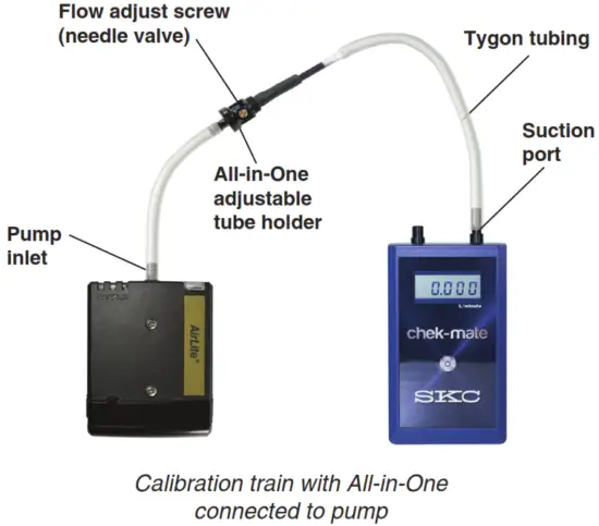
- Attach the Tygon tubing of the All-in-One to the pump inlet. See calibration train at right. Note: If the pump flow faults shortly after the holder is attached, check that the needle valve is open by using a small flat-head screwdriver to turn the flow adjust screw on the holder slightly counterclockwise. If the flow fault continues, check that the two small holes on the bottom of the built-in CPC are not blocked. If needed, clean holes with a small pick and blow any particles away with a puff of air.
- Break tips off the representative sorbent tube and insert it into the rubber sleeve on the All-in-One (arrow on the tube points toward the holder). Ensure that the sorbent tube fits snugly in the rubber sleeve prior to sampling to avoid air leakage. Two sleeves, each with a different inner diameter, are supplied with the All-in-One.
- Using flexible tubing, connect the calibrator outlet to the inlet of the representative sorbent tube in the holder.
 In the next step, do not shut off flow completely with a flow adjust screw or use an oversize screwdriver to adjust flow -valve or thread seat damage may result.
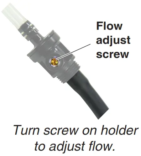
 - Do not adjust the flow on the pump. Adjust the flow rate through the representative sorbent tube using a small flat-head screwdriver to turn the flow adjust screw on the All-in-One (counterclockwise to increase, clockwise to decrease) until the calibrator displays the method-specified flow rate. Take a minimum of three readings and record the average flow rate, as per OSHA/NIOSH instructions.
- When calibration is complete, turn off the pump by pressing the on/off button. Disconnect the calibrator and tubing from the representative sorbent tube inlet.
Set-Up/Sample with Single Tube
![]() Do not operate AirLite with Timer in hazardous or explosive locations. The pump is designed for applications that do not require intrinsic safety.
Do not operate AirLite with Timer in hazardous or explosive locations. The pump is designed for applications that do not require intrinsic safety.
- For maximum run time insert new batteries in the pump before each sampling period. If using rechargeable AA 1.2-volt NiMH batteries, expect approximately half the run time stated for disposable batteries.
- Allow the pump to equilibrate after moving it from one temperature extreme to another.
- Protect sample pump from the weather when sampling outdoors.
- Calibrate/verify pump flow rate before and after each sampling operation using the tube holder and pump to be used for sampling.

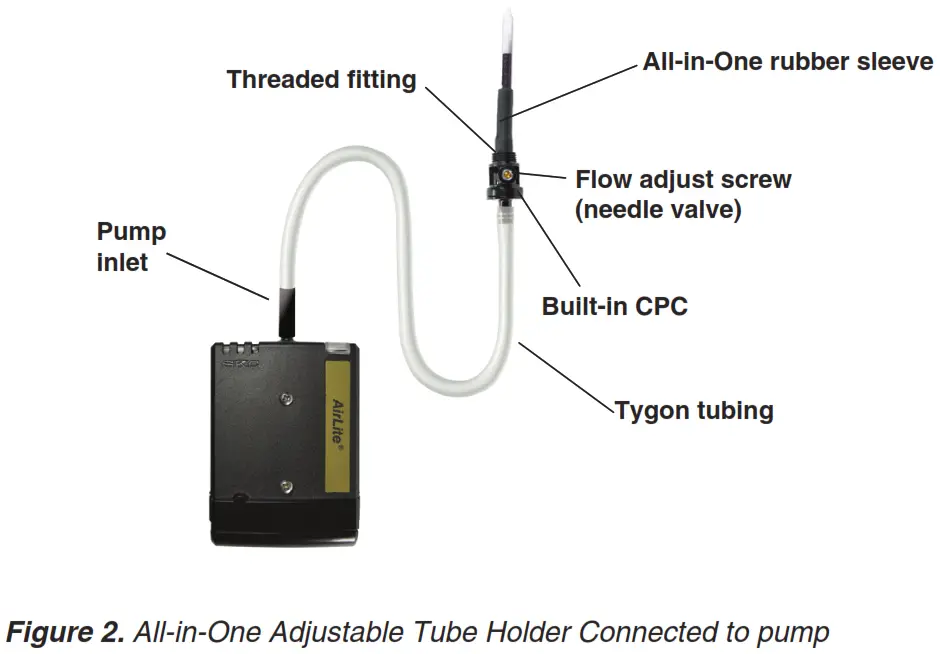
- Replace the representative sorbent tube used for calibrating flow with a new unexposed sorbent tube for sample collection. Note: Ensure the sorbent tube fits snugly in the rubber sleeve of the All-in-One before sampling to avoid any air leakage. Two sleeves, each with different inner diameter (ID), are supplied. See Figure 2.
- Place the protective tube cover over the sorbent tube and thread it into place on the All-in-One until secure.
- Place the sorbent tube that was appropriate for sampling. For personal sampling, clip the sample medium to the worker in the breathing zone and the pump to the worker’s belt.
- Press the on/off button to turn on the pump and start sampling. Record the start time and other pertinent information.
Possible Displays During Sampling
Flow or Battery Fault Shutdown – If the pump is unable to compensate due to excessive back pressure or a low battery condition exists, it will shut down and timing functions will pause. The LCD will display either a battery-shaped icon or a flow fault icon () depending on the cause of the shutdown. Upon flow fault, the pump will attempt to restart up to five times. To restart from flow fault, correct the blockage and press the on/off button twice. The elapsed run time display will reset to 0 when the pump is restarted. If the battery icon is displayed, recharge the battery before sampling.
Displayed Elapsed Run Time – Elapsed run time is displayed continuously on the LCD. For elapsed times after 999 minutes, the display will show the count starts from 0 to 999 again. - At the end of the sampling period, press the on/off button and record stop time and other pertinent information.
- Cap the sample tube and send it with blanks and pertinent sampling information to a laboratory for analysis.
- Verify the flow.
a. Turn on the pump and reinstate the calibration train and sample media.
b. Take three readings and record the average value as the post-sample flow rate. Do not adjust the pump flow rate during this step.
c. Compare the pre and post-sample flow rates. Note in sampling documentation if the values differ by more than ± 5%.
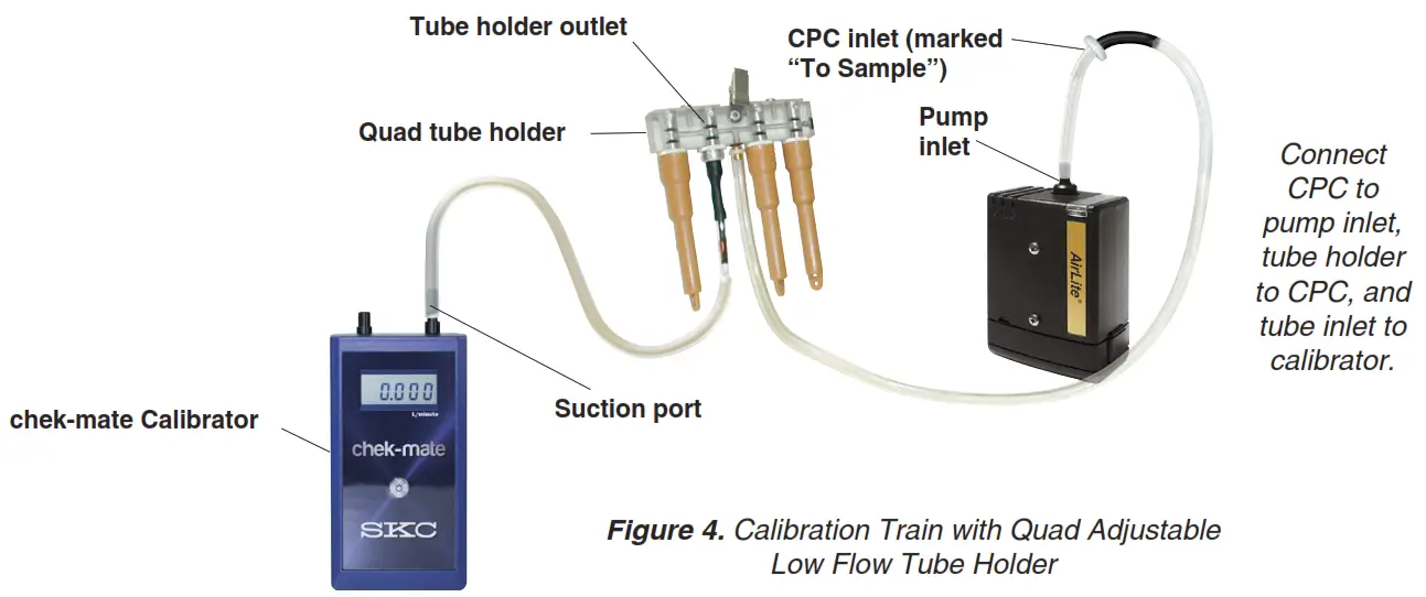
Using a CPC and Dual, Tri, or Quad Adjustable Low Flow Tube Holder (Figure 3)
Set/Calibrate Flow Rate for Multiple Tubes
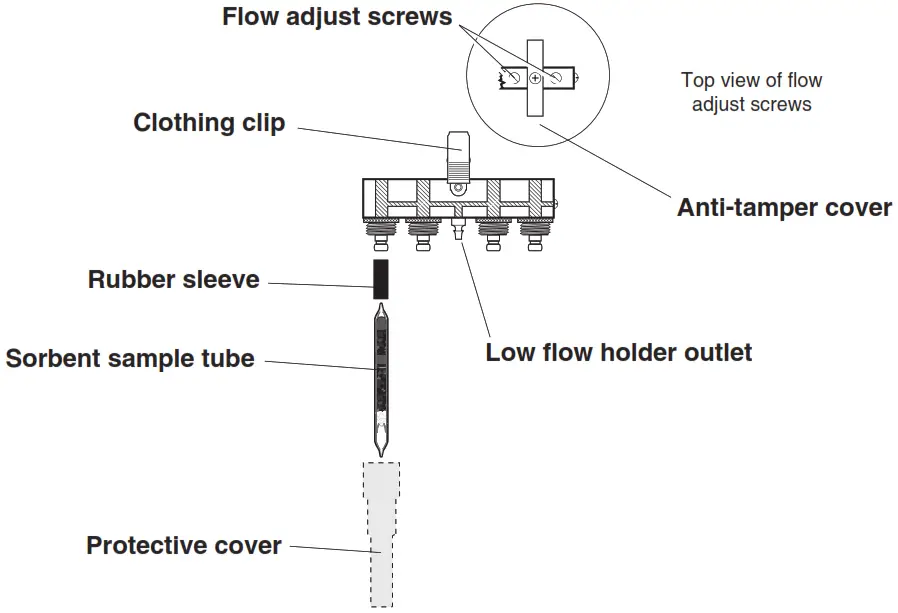
Figure 3. Quad Adjustable Low Flow Tube Holder![]() Do not operate the pump in hazardous or explosive locations. The pump is designed for applications that do not require intrinsic safety.
Do not operate the pump in hazardous or explosive locations. The pump is designed for applications that do not require intrinsic safety.
- Requires Constant Pressure Controller (CPC) and Adjustable Low Flow Tube Holder (see Accessories). The low flow tube holder used with CPC allows up to four tube samples to be taken simultaneously, each at different flow rates if desired.
- Allow the pump to equilibrate after moving it from one temperature extreme to another.
- Calibrate/verify pump flow rate before and after each sampling operation using the tube holder and pump to be used for sampling.
- Set the flow rate through the pump first and then calibrate the flow rate through each sorbent tube.
Pump Flow Rate![]() Follow these important steps before proceeding.
Follow these important steps before proceeding.
- Ensure that the battery is fully charged and that the pump has run for 5 minutes before calibrating. Leave the pump running.
- Prepare a calibrator (see calibrator instructions). Using flexible tubing, connect the calibrator outlet (suction port) to the pump inlet.
- Calculate the sum of all-tube flow rates. The maximum flow rate through any one tube is 500 ml/min.*
a. If the sum is ≤ 1000 ml/min, set the pump flow rate to 1.5 L/min.
b. If the sum is > 1000 ml/min, multiply that number by 0.15 and total the two numbers. Set the pump flow rate for the resulting new sum. (Example: Sampling with three sorbent tubes, each with a flow rate of 500 ml/min.* The sum of the tube flow rates is calculated as 3 x 500 = 1500. Determining a 15% higher flow rate is calculated as 1500 x 0.15 = 225. Calculating the final pump flow setting would be 1500 + 225 = 1725 ml/min.)
* Backpressure across some sample tubes can be higher than average. In these instances, the maximum flow rate of 500 ml/min per tube may not be achieved. - Using a small screwdriver, turn the flow adjustment screw on top of the pump (Figure 1), clockwise to increase or counterclockwise to decrease flow until the calibrator indicates the required flow rate.
- Remove tubing from the pump inlet and calibrator outlet.
Flow Rate Through Sorbent Tubes
- Attach the tubing on the CPC outlet (side of the CPC without a label) to the pump inlet. Attach the Adjustable Low Flow Holder to the CPC inlet (marked “To Sample”). See Figure 4.
- Break tips off the representative sorbent tubes and insert them into the rubber sleeves on the holder (arrow on each tube pointing toward the pump). Place unopened tubes in any unused ports to “seal” them.
- Label all representative sorbent tubes and ports.
- Using flexible tubing, connect the exposed end of the first representative tube to the calibrator outlet (suction port).

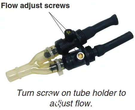
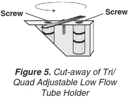
- Using a small screwdriver, loosen and turn the brass flow adjust screw (see above right) directly beneath the port holding the first active representative tube to be calibrated (clockwise to increase, counterclockwise to decrease) until the calibrator indicates the method-specified flow rate. Do not adjust the flow rate on the pump. Note: For tri and quad models, first rotate each anti-tamper cover to expose the flow adjust screws, then adjust the appropriate one until the calibrator indicates the desired flow (Figures 3 and 5).

- Repeat Steps 4 and 5 for each active representative tube. Note: Changing the flow on one tube will not affect the flow rate through the remaining tubes.

- Once the flow is calibrated for each active representative tube, it is recommended practice to re-check the flow rate through all representative tubes before removing them. Any adjustment should be minimal.
Set-Up/Sample with Multiple Tubes
![]() Do not operate AirLite with Timer in hazardous or explosive locations. The pump is designed for applications that do not require intrinsic safety.
Do not operate AirLite with Timer in hazardous or explosive locations. The pump is designed for applications that do not require intrinsic safety.
- Requires Constant Pressure Controller (CPC) and Adjustable Low Flow Tube Holder (see Accessories). The low flow tube holder used with CPC allows up to four tube samples to be taken simultaneously, each at different flow rates if desired.
- Allow the pump to equilibrate after moving it from one temperature extreme to another.
- Protect sample pump from the weather when sampling outdoors.
- For a maximum run time, insert new batteries before each sampling period. If using rechargeable AA 1.2-volt batteries, expect approximately half the run time stated for disposable batteries.
- The two small inlet ports on the bottom of the CPC can become blocked. Inspect these ports periodically for blockage that can occur when sampling in dusty environments. Such blockage may cause back pressure to increase. Clean ports with a small pick and blow away any particles with a puff of air.

- Replace the representative sorbent tubes used for calibration with new unexposed sorbent tubes for sample collection.
- Place a protective tube cover over each tube and thread into place on the holder until secure.
- Place the adjustable holder with tubes that were appropriate for sampling. For personal sampling, clip the low flow tube holder to the worker in the breathing zone and the pump to the worker’s belt. See right.
- Press the on/off button to turn on the pump and start sampling. Record the start time and other pertinent information.
Possible Displays During Sampling
Flow or Battery Fault Shutdown – If the pump is unable to compensate due to excessive back pressure or a low battery condition exists, it will shut down and timing functions will pause. The LCD will display either a battery-shaped icon or a flow fault icon () depending on the cause of the shutdown. Upon flow fault, the pump will attempt to restart up to five times. To restart from flow fault, correct the blockage and press the on/off button twice. The elapsed run time display will reset to 0 when the pump is restarted. If the battery icon is displayed, recharge the battery before sampling.
Displayed Elapsed Run Time – Elapsed run time is displayed continuously on the LCD. For elapsed times after 999 minutes, the display will show the count starts from 0 to 999 again. - At the end of the sampling period, press the on/off button and record stop time and other pertinent information.
- Cap the sample tubes and send with blanks and pertinent sampling information to a laboratory for analysis.
- Verify the flow.
a. Turn on the pump and reinstate the calibration train and sample media.
b. Take three readings and record the average value as the post-sample flow rate. Do not adjust the pump flow rate during this step.
c. Compare the pre and post-sample flow rates. Note in sampling documentation if the values differ by more than ± 5%.
Maintenance
See Insert/Replace the Batteries.
Pump Service
Pumps under warranty should be sent to SKC Inc. for service. See Limited Warranty and Return Policy.
Accessories/Replacement Parts
Accessories
| Accessories | Cat. No. | |
| Medium Flow chek-mate Calibrator with CalChek, 0.50 to 5 L/min, includes a 9-volt alkaline battery with NIST standard traceable calibration certificate with UK standard traceable calibration certificate with ISO standard traceable calibration certificate | 375-0550 375-0550S 375-0550N | |
| Low Flow Sampling Accessories Low Flow Adapter Kit includes an All-in-One adjustable tube holder and Type-A Protective Tube Cover | 110-500 | |
| Constant Pressure Controller, required for adjustable low flow holders below Dual Adjustable Low Flow Tube Holder Tri Adjustable Low Flow Tube Holder Quad Adjustable Low Flow Tube Holder | 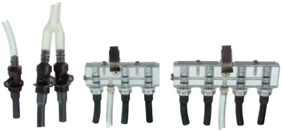 | 224-26-CPC 224-26-02 224-26-03 224-26-04 |
| Protective Cover for Sorbent Tubes Type A – 6-mm OD x 70-mm L, included in the Low Flow Adapter Kit above Type B – 8-mm OD x 110-mm L Type C – 10-mm OD x 150-mm L Type D – 10-mm OD x 220-mm L |  | 224-29A 224-29B 224-29C 224-29D |
| Miscellaneous Screwdriver Set (included with the pump) Protective Nylon Pouch with belt loop, black Waist Strap | 224-11 224-902 224-12 | |
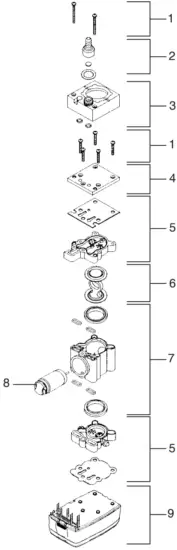
Replacement Parts
| Replacement Parts | Cat. No. | |
| 1 | Stack screws | P51891 |
| 2 | Inlet hose connector | P20106 |
| 3 | Pulsation dampener | P2010802 |
| 4 | Stack plate | N/A |
| 5 | Valve plates (top and bottom) | P213201 |
| 6 | Diaphragm/Yoke assembly | P22417HC |
| 7 | Pump body | P22417G |
| 8 | Motor/Eccentric | P51890 |
| 9 | Pump base | P20182 |
SKC Limited Warranty and Return Policy
SKC products are subject to the SKC Limited Warranty and Return Policy, which provides SKC’s sole liability and the buyer’s exclusive remedy. To view the complete SKC Limited Warranty and Return Policy, go to skcinc.com/warranty.
Appendix
Performance Profile
Flow Range | 1000 to 3000 ml/min (5 to 500 ml/min requires low flow accessories. See Accessories.) | ||||||||||||||||||||||||||||||||||||
| Flow Control | Patented* system holds constant flow to ± 5% of set-point | ||||||||||||||||||||||||||||||||||||
| Compensation Range(for a minimum of 8-hour operation) | 1000 ml/min at 30 inches water back pressure 2000 ml/min at 20 inches water back pressure 3000 ml/min at 10 inches water back pressure | ||||||||||||||||||||||||||||||||||||
| The typical back pressure of sampling media (inches of water) |
Compare the information in this table to the pump compensation range to determine appropriate applications. | ||||||||||||||||||||||||||||||||||||
| Temperature Ranges | Operating: 32 to 104 F (0 to 40 C) Storage: -4 to 113 F (-20 to 45 C) | ||||||||||||||||||||||||||||||||||||
| Compensated Temperature Range | 41 to 122 F (5 to 50 C) | ||||||||||||||||||||||||||||||||||||
| Operating Humidity | 0 to 95% non-condensing | ||||||||||||||||||||||||||||||||||||
| Power | Three standard AA alkaline batteries Rechargeable AA-size 1.2-volt NiMH batteries may be used but will provide approximately half the run time stated for disposable batteries. | ||||||||||||||||||||||||||||||||||||
| Tubing | Requires 1/4-inch ID tubing | ||||||||||||||||||||||||||||||||||||
| Case/Material | Plastic, RFI/EMI-shielded | ||||||||||||||||||||||||||||||||||||
| Certifications | CE marked | ||||||||||||||||||||||||||||||||||||
| Battery Run Time | Depends on the batteries used. See Table 1. | ||||||||||||||||||||||||||||||||||||
| Intrinsic Safety | Do not operate AirLite with Timer in hazardous or explosive locations. AirLite is designed for applications that do not require intrinsic safety. | ||||||||||||||||||||||||||||||||||||
| Dimensions | 4.6 x 3 x 1.75 in (11.7 x 7.6 x 4.4 cm) | ||||||||||||||||||||||||||||||||||||
| Weight (including batteries) | 12 oz (340 grams) |
* U.S. Patent No. 6,741,056
Table 1. Pump Run Time in Hours with Alkaline Batteries
- To prevent corrosion of battery terminals, remove batteries when AirLite with Timer will not be used for an extended time.
- Increases in back pressure in sampling conditions due to buildup on the filter can decrease battery life.
- For a maximum run time, insert new batteries in the pump before sampling.
- If using rechargeable AA 1.2-volt NiMH batteries, the run time will be approximately half that stated for disposable batteries.
Following are typical run times achieved when using a new pump and new disposable AA alkaline batteries. Data is sorted by type of sample media. All run times are listed in hours. Pump and battery performance may vary.
Mixed Cellulose (MCE) Filter, 0.8-µm pore size
| Filter Diameter | 37 mm | 37 mm | 37 mm | 25 mm | 25 mm |
| Flow Rate | 1 L/min | 2 L/min | 2.5 L/min | 1 L/min | 2 L/min |
| Duracell® Standard | 23.5 | 14.5 | 13.5 | 18.5 | 10.5 |
| Rayovac® Maximum | 20.0 | 16.5 | 14.0 | 16.5 | 11.0 |
| Wal-Mart EverActive | 24.0 | 16.0 | 10.5 | 18.0 | 10.5 |
| Eveready Alkaline | 20.0 | 14.0 | 13.0 | 17.0 | Not tested |
Polyvinyl Chloride (PVC) Filter, 5.0-µm pore size
| Filter Diameter | 37 mm | 37 mm | 37 mm | 25 mm | 25 mm |
| Flow Rate | 1 L/min | 2 L/min | 2.5 L/min | 1 L/min | 2 L/min |
| Duracell Standard | 23.5 | 15.5 | 17.0 | 23.0 | 10.5 |
| Rayovac Maximum | 29.5 | 16.5 | 14.0 | 18.5 | 13.0 |
| Wal-Mart EverActive | 24.5 | 20.5 | 15.5 | 20.5 | 11.5 |
Glass Fiber Filter
| Filter Diameter | 37 mm | 37 mm | 37 mm | 37 mm |
| Flow Rate | 1 L/min | 2 L/min | 2.5 L/min | 3 L/min |
| Energizer | 29.5 | 18.0 | 21.0 | 18.5 |
| Rayovac Maximum | 26.5 | 23.5 | 23.0 | 14.0 |
| Wal-Mart EverActive | 33.5 | 24.5 | 17.5 | 19.0 |
| Filter Diameter | 25 mm | 25 mm | 25 mm | 25 mm |
| Flow Rate | 1 L/min | 2 L/min | 2.5 L/min | 3 L/min |
| Energizer | 29.0 | 18.5 | 18.5 | 12.0 |
| Rayovac Maximum | 9.5 | 19.5 | 14.5 | 13.5 |
| Wal-Mart EverActive | 26.0 | 20.0 | 14.5 | 14.0 |
skcinc.com
Form 37182
Rev 211108


