BAFANG DP C244.CAN Mounting Parameters Display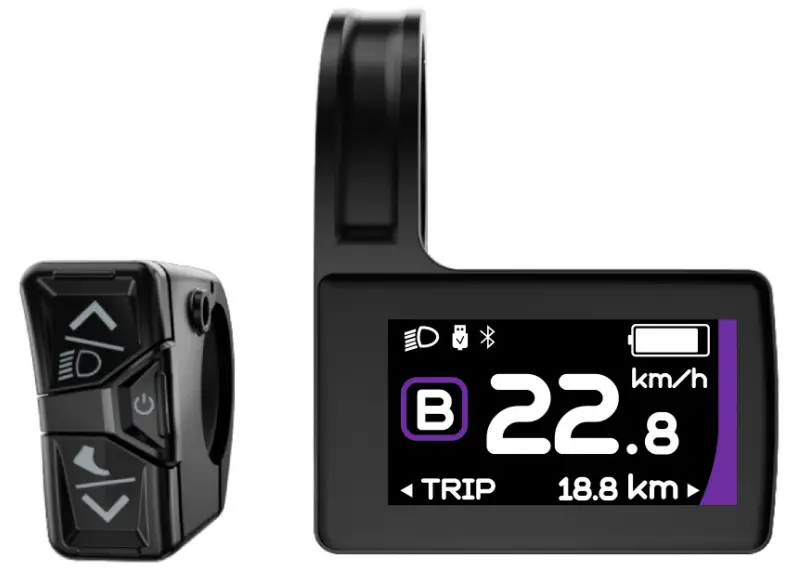
IMPORTANT NOTICE
- If the error information from the display cannot be corrected according to the instructions, please contact your retailer.
- The product is designed to be waterproof. It is highly recommended to avoid submerging the display under water.
- Do not clean the display with a steam jet, high-pressure cleaner or water hose.
- Please use this product with care.
- Do not use thinners or other solvents to clean the display. Such substances can damage the surfaces.
- Warranty is not included due to wear and normal use and aging.
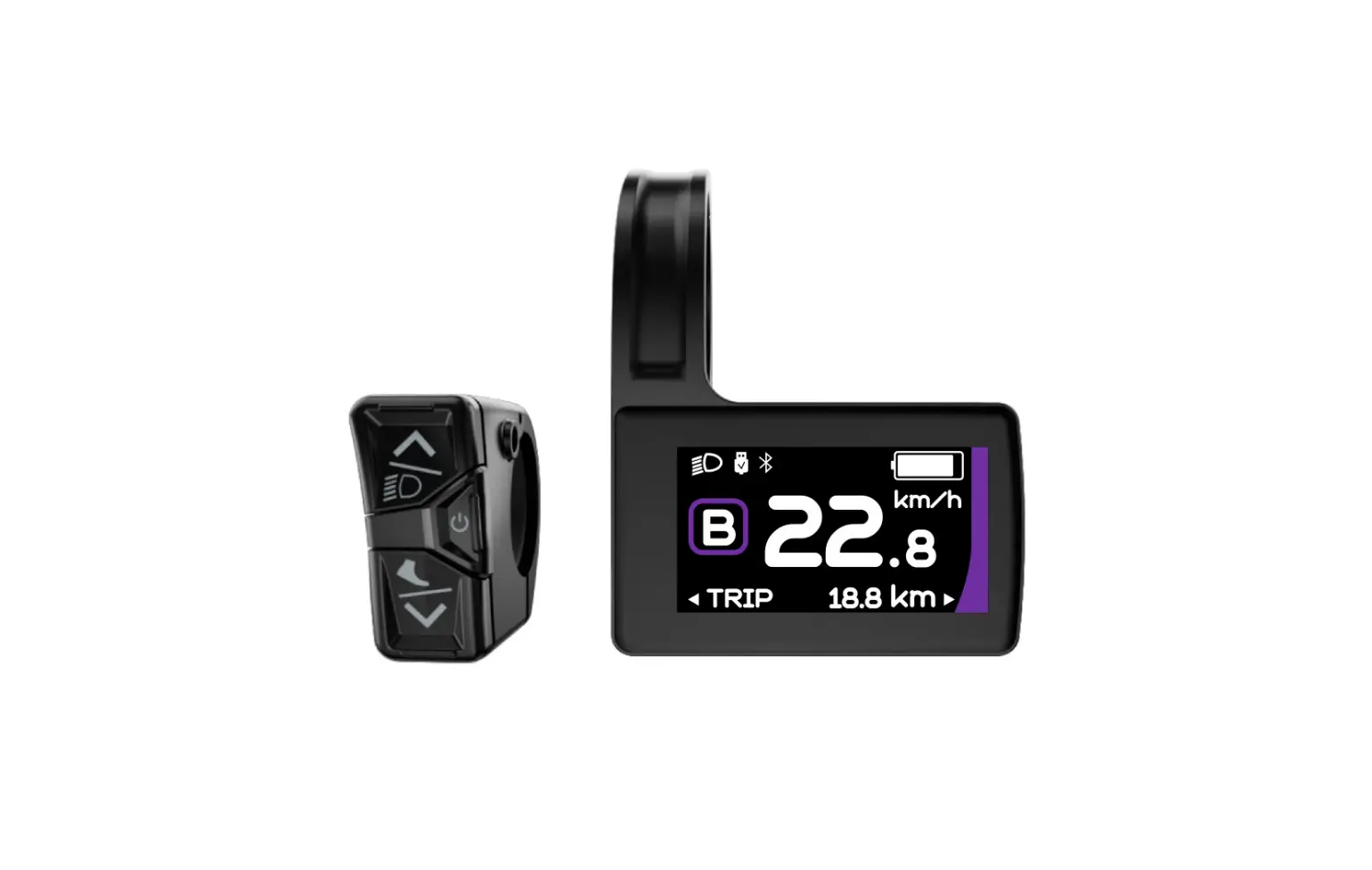
INTRODUCTION OF DISPLAY
- Model: DP C244.CAN/ DP C245.CAN
- The housing material is ABS; the LCD display windows is made of tempered glass:

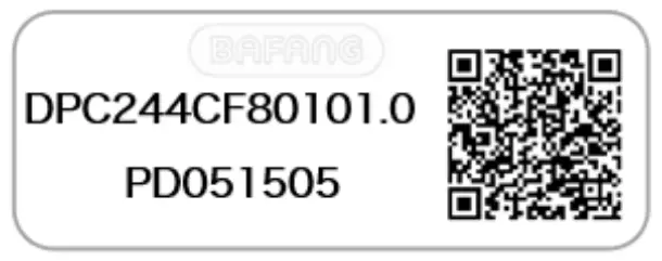
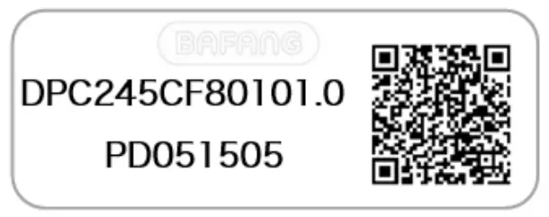
- The label marking is as follows:


 Note: Please keep the QR code label attached to the display cable. The information from the Label is used for a later possible software update
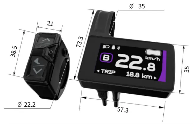


PRODUCT DESCRIPTION
Specifications
- Operating temperature: -20℃~45℃
- Storage temperature: -20℃~60℃
- Waterproof: IP65
- Storage Humidity: 30%-70% RH
Functional Overview
- CAN communication protocol
- Speed indication (including the real-time speed, max. speed and average speed)
- Unit switching between km and mile
- Battery capacity indicaton
- Automatic sensors explanation of the lighting system
- Brightness setting for backlight
- 6 power assist modes
- Mileage indication (including single-trip distance TRIP and total distance ODO, the highest mileage is 99999)
- Intelligent indication (including remainingdistance RANGE and energy consumption CALORIE)
- Error code indication
- Walk assistance
- USB charge (5V and 500mA)
- Service indication
- Bluetooth Function (only in DP C245.CAN)
DISPLAY
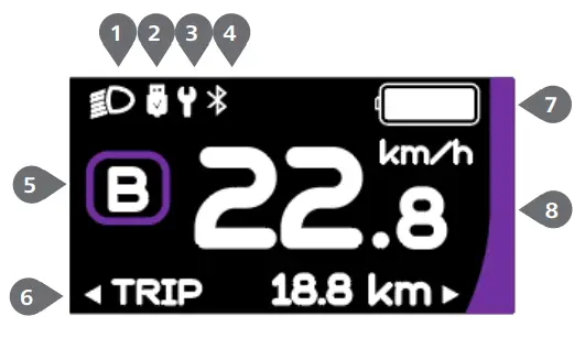
- Headlight indication
- USB charge indication
- Service indication
- Bluetooth indication (only light up in DP C245.CAN)
- Power assist mode indication
- Multifunction indication
- Battery capacity indication
- Speed in real-time
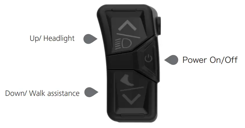
KEY DEFINITION
NORMAL OPERATION
Power ON/OFF
Press ![]() and hold (>2S) to power on the HMI, and the HMI begin to show the boot up LOGO.
and hold (>2S) to power on the HMI, and the HMI begin to show the boot up LOGO.
Press ![]() and hold (>2S) again to power off the HMI.
and hold (>2S) again to power off the HMI.
If the automatic shutdown time is set to 5 minutes (set in function “Auto Off”), the HMI will be automatically turned off within this set time, when it is not operated.
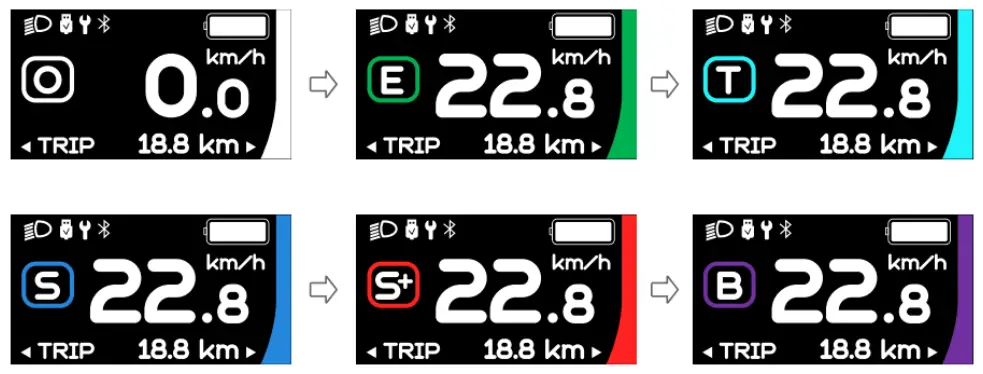
Power Assist Mode Selection
When HMI powers on, briefly press ![]() or
or ![]() to select the power assist mode and change the output power. The lowest mode is E, the highest mode is B (which can be set). On the default is mode E, number “0”means no power assistance.
to select the power assist mode and change the output power. The lowest mode is E, the highest mode is B (which can be set). On the default is mode E, number “0”means no power assistance.
| Mode | Color | Definition |
| Eco | green | the most economic mode |
| Tour | blue | the most economic mode |
| Sport | indigo | the sport mode |
| Sport+ | red | the sport plus mode |
| Boost | purple | the strongest sport mode |
Multifunction Selection
Briefly press![]() button to switch the different function and information.
button to switch the different function and information.
Circularly show single trip distance (TRIP,km) → total distance (ODO,km) → maximum speed (MAX,km/h) → average speed (AVG,km/h) → remaining distance (Range,km) → riding cadence (Cadence,rpm) → energy consumption (Cal,KCal) → riding time (TIME,min) →cycle.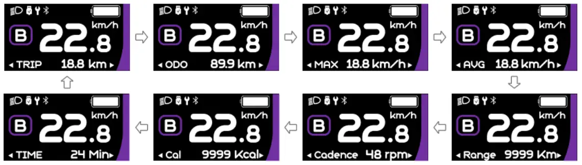
Headlights / Backlighting
Press and hold ![]() (>2S) to turn on the headlight and reduce the backlight brightness.
(>2S) to turn on the headlight and reduce the backlight brightness.
Press and hold ![]() (>2S) again to turn off the headlight and increase the backlight brightness.
(>2S) again to turn off the headlight and increase the backlight brightness.
The brightness of backlight can be set in function“Brightness” within 5 levels.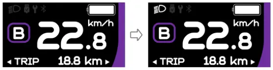
Walk Assistance
Note: The walk assistance can only be activated with a standing pedelec.
Briefly press![]() button until this symbol
button until this symbol ![]() appears. Next keep pressing the button
appears. Next keep pressing the button![]() until the walk assistance is activated and the
until the walk assistance is activated and the![]() symbol is flashing.(If no speed signal is detected, the real-time speed is shown as 2.5km/h.) Once releasing the
symbol is flashing.(If no speed signal is detected, the real-time speed is shown as 2.5km/h.) Once releasing the![]() button, it will exit the walk assistance and the
button, it will exit the walk assistance and the![]() symbol stops flashing. If no operation within 5s, the display will automatically return to 0 mode.
symbol stops flashing. If no operation within 5s, the display will automatically return to 0 mode.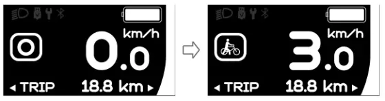
Battery Capacity Indication
The percentage of current battery capacity and total capacity is displayed from 100% to 0% according to the actual capacity.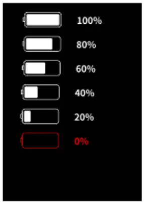
USB Charge Function
When the HMI is off, insert the USB device to the USB charging port on the HMI, and then turn on HMI to charge. When the HMI is on, it can direct charge for USB device. the maximum charging voltage is 5V and the maximum charging current is 500mA.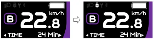
Bluetooth Function
Note: Only DP C245.CAN is the Bluetooth version.
DP C245 equipped with Bluetooth 5.0 ca be connected to the Bafang Go APP. The customer also can develop their own APP based on the SDK provided by BAFANG.
This display can be connected to the SIGMA heartbeat band and shows it on display, and can also send data to the mobile phone.
The data that can be sent to the mobile phone are as follow: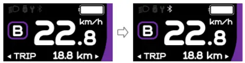
| No. | Function |
| 1 | Speed |
| 2 | Battery capacity |
| 3 | Support level |
| 4 | Battery info. |
| 5 | Sensor signal |
| 6 | Remaining distance |
| 7 | Energy consumption |
| 8 | System part info. |
| 9 | Current |
| 10 | Heartbeat |
| 11 | Single distance |
| 12 | Total distance |
| 13 | Headlight status |
| 14 | Error code |
(Bafang Go for AndroidTM and iOSTM )

SETTINGS
After the HMI powered on, press and hold ![]() and
and ![]() button (at the same time) to enter into the setting interface. Briefly press (<0.5S)
button (at the same time) to enter into the setting interface. Briefly press (<0.5S)![]() or
or ![]() button to select “Setting”, “Information” or “Exit” , then briefly press (<0.5S)
button to select “Setting”, “Information” or “Exit” , then briefly press (<0.5S) ![]() button to confirm.
button to confirm.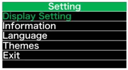
“Setting” interface
After the HMI powered on, press and hold ![]() and
and ![]() button to enter into the setting interface. Briefly press (<0.5S)
button to enter into the setting interface. Briefly press (<0.5S) ![]() or
or ![]() to select “Setting” and then briefly press (<0.5S)
to select “Setting” and then briefly press (<0.5S)![]() to confirm.
to confirm.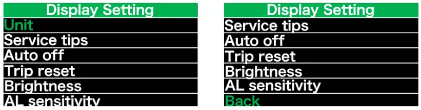
“Unit” Selections in km/Miles
Briefly press ![]() or
or ![]() to select “Unit”, and briefly press
to select “Unit”, and briefly press![]() to enter into the item. Then choose between “Metric” (kilometer) or “Imperial” (mile) with the
to enter into the item. Then choose between “Metric” (kilometer) or “Imperial” (mile) with the![]() or
or ![]() button.
button.
Once you have chosen your desired selection, press the button (<0.5S)![]() to save and exit back to the “Setting” interface.
to save and exit back to the “Setting” interface.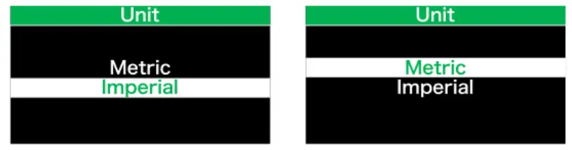
“Auto Off” Set automatic Off time
Briefly press ![]() or
or ![]() to select “Auto Off”, and briefly press
to select “Auto Off”, and briefly press![]() to enter into the item.
to enter into the item.
Then select the automatic Off time as “OFF”/ “1”/ “2”/ “3”/ “4”/ “5”/ “6”/ “7”/ “8”/ “9”/ “10” with the ![]() or
or ![]() button. Once you have chosen your desired selection, press the button (<0.5S)
button. Once you have chosen your desired selection, press the button (<0.5S) ![]() to save and exit back to the “Setting” interface.
to save and exit back to the “Setting” interface.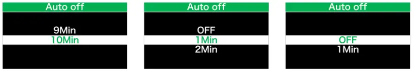
Note: “OFF” means the “Auto Off” function is off.
“Brightness” Display brightness
Briefly press ![]() or
or ![]() to select “Brightness”, and briefly press
to select “Brightness”, and briefly press![]() to enter into the item. Then select the percentage as “100%” / “75%” / “50%” / “25%” with the
to enter into the item. Then select the percentage as “100%” / “75%” / “50%” / “25%” with the![]() or
or![]() button. Once you have chosen your desired selection, press the button (<0.5S)
button. Once you have chosen your desired selection, press the button (<0.5S)![]() to save and exit back to the “Setting” interface.
to save and exit back to the “Setting” interface.
“AL Sensitivity” Set light sensitivity
Briefly press or to select “AL Sensitivity”, and briefly press to enter into the item. Then select the level of the light sensitivity as “OFF”/“1”/ “2”/“3”/“4”/“5” with the or button. Once you have chosen your desired selection, press the button (<0.5S) to save and exit back to the “Setting” interface.
Note: “OFF” means light sensor is off. Level 1 is the weakest sensitivity and level 5 is the strongest sensitivity.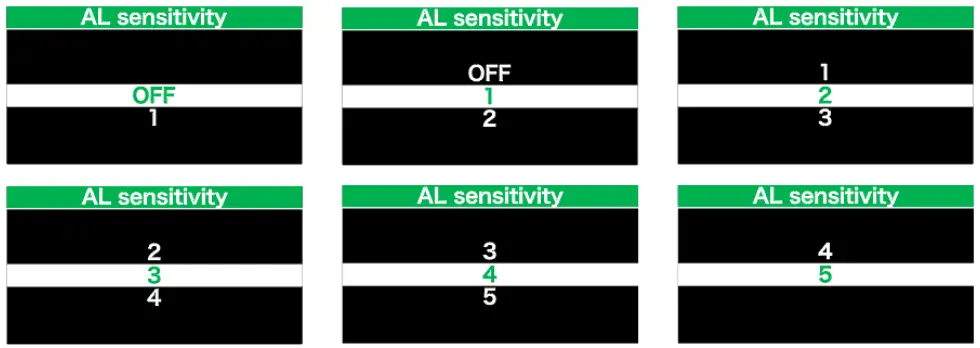
“TRIP Reset” Set reset function for single-trip
Briefly press ![]() or
or ![]() to select “TRIP Reset”, and briefly press
to select “TRIP Reset”, and briefly press![]() to enter into the item. Then select “NO”/“YES” (“YES”- to clear, “NO”-no operation) with the
to enter into the item. Then select “NO”/“YES” (“YES”- to clear, “NO”-no operation) with the ![]() or
or ![]() button. Once you have chosen your desired selection, press the button (<0.5S)
button. Once you have chosen your desired selection, press the button (<0.5S)![]() to save and exit back to the “Setting” interface.
to save and exit back to the “Setting” interface.
Note: The riding time(TIME), average speed (AVG) and maximum speed (MAXS) will be reset simultaneously when you reset TRIP
“Service” Turn on/off the Service indication
Briefly press![]() or
or ![]() to select “Service”, and briefly press
to select “Service”, and briefly press ![]() to enter into the item.
to enter into the item.
Then select “OFF”/“ON” (“ON” means Service indication is on; “OFF” means Service indication is off) with the![]() or
or ![]() button.
button.
Once you have chosen your desired selection, press the button (<0.5S)![]() to save and exit back to the “Setting” interface.
to save and exit back to the “Setting” interface.
Note: The default setting is OFF. If the ODO is more than 5000 km, the “Service” indication and mileage indication will flash for 4S.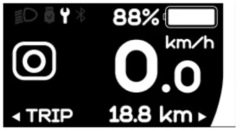
“Information”
After the HMI powered on, press and hold![]() and
and ![]() to enter into the setting function. Briefly press (<0.5S)
to enter into the setting function. Briefly press (<0.5S) ![]() or
or ![]() to select “Information” and then briefly press (<0.5S)
to select “Information” and then briefly press (<0.5S)![]() to confirm.
to confirm.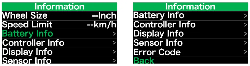
Note: All information here cannot be changed, it is to be viewed only.
“Wheel Size”
After entering the “Information” page, you can see “Wheel Size –Inch” directly.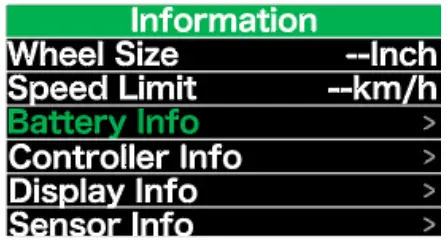
“Speed Limit”
After entering the “Information” page, you can see “Speed Limit –km/h” directly.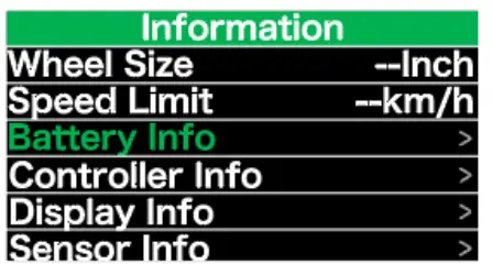
“Battery Info”
Briefly press or to select “Battery Info”, and briefly press to enter, then briefly press or to view the battery data (b01 → b04 → b06 → b07 → b08 → b09→ b10 → b11 → b12 → b13 → d00 → d01 → d02 → … → dn).
Press the button (<0.5S) to exit back to the “Information” interface.
Note: If the battery doesn’t have communication function, you won’t see any data from battery.
View the battery information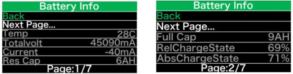
View the hardware and software version of battery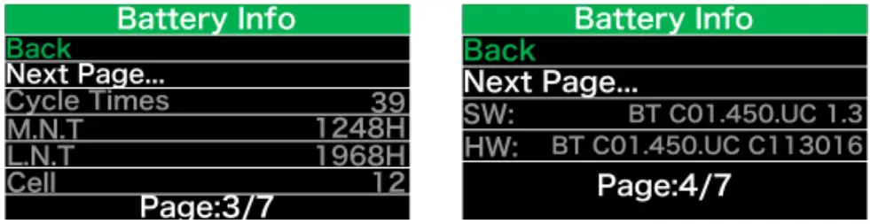
| Code | Code Definition | Unit |
| b01 | Current temperature | ℃ |
| b04 | Battery voltage | mV |
| b06 | Current | mA |
| b07 | Remaining battery capacity | mAh |
| b08 | Battery capacity of Full charged | mAh |
| b09 | Relative SOC | % |
| b10 | Absolute SOC | % |
| b11 | Cycle Times | times |
| b12 | Max Uncharge Time | Hour |
| b13 | Last Uncharge Time | Hour |
| d00 | The number of cell | |
| d01 | Voltage Cell 1 | mV |
| d02 | Voltage Cell 2 | mV |
| dn | Voltage Cell n | mV |
NOTE: If no data is detected, “–” will be displayed.
“Display Info”
Briefly press ![]() or
or ![]() to select ”Display Info”, and briefly press
to select ”Display Info”, and briefly press ![]() to enter, briefly press
to enter, briefly press ![]() or
or ![]() to view “Hardware Ver” or “Software Ver”.
to view “Hardware Ver” or “Software Ver”.
Press the button (<0.5S) ![]() to exit back to the “Information” interface.
to exit back to the “Information” interface.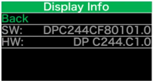
“Ctrl Info”
Briefly press ![]() or
or ![]() to select ”Ctrl Info”, and briefly press
to select ”Ctrl Info”, and briefly press![]() to enter, briefly press
to enter, briefly press ![]() or
or ![]() to view “Hardware Ver” or “Software Ver”.
to view “Hardware Ver” or “Software Ver”.
Press the button (<0.5S)![]() to exit back to the “Information” interface.
to exit back to the “Information” interface.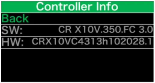
“Sensor Info”
Briefly press or to select ”Sensor Info”, and briefly press to enter, briefly press or to view “Hardware Ver” or “Software Ver”.
Press the button (<0.5S) to exit back to the “Information” interface.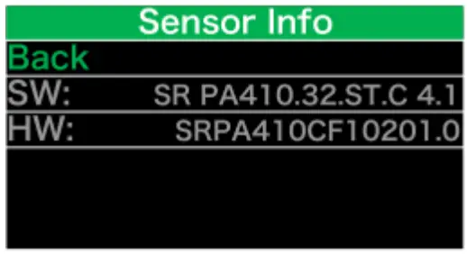
NOTE: If your Pedelec doesn’t have torque sensor, “–” will be displayed.
“Error Code”
Briefly press ![]() or
or ![]() to select ”Error Code”, and then briefly press
to select ”Error Code”, and then briefly press ![]() to enter, briefly press
to enter, briefly press ![]() or
or ![]() to view message of error for last ten times by “E-Code00” to “E-Code09”.Press the button (<0.5S)
to view message of error for last ten times by “E-Code00” to “E-Code09”.Press the button (<0.5S) ![]() to exit back to the “Information” interface.
to exit back to the “Information” interface.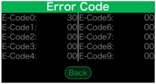
ERROR CODE DEFINITION
The HMI can show the faults of Pedelec. When a fault is detected, one of the following error codes will be indicated too.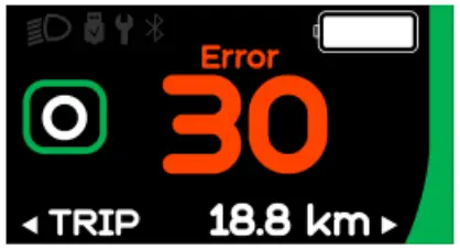
 Note: Please read carefully the description of the error code. When the error code appears, please first restart the system. If the problem is not eliminated, please contact your dealer or technical personnel.
| Error | Declaration | Troubleshooting |
| 04 | The throttle has fault. | 1. Check the connector and cable of the throttle are not damaged and correctly connected. 2. Disconnect and reconnect the throttle, if still no function please change the throttle. |
| 05 | The throttle is not back in its correct position. | Check the connector from the throttle is correctly connected. If this does not solve the problem, please change the throttle. |
| 07 | Overvoltage protection | 1. Remove and re-Insert the battery to see if it resolves the problem. 2. Using the BESST tool update the controller. 3. Change the battery to resolve the problem. |
| 08 | Error with the hall sensor signal inside the motor | 1. Check all connectors from the motor are correctly connected. 2. If the problem still occurs, please change the motor. |
| 09 | Error with the Engine phase’s | Please change the motor. |
| 10 | The temperature inside the en- gine has reached its maximum protection value | 1. Turn off the system and allow the Pedelec to cool down. 2. If the problem still occurs, please change the motor. |
| 11 | The temperature sensor inside the motor has an error | Please change the motor. |
| 12 | Error with the current sensor in the controller | Please change the controller or contact your supplier. |
| 13 | Error with the temperature sensor inside of the battery | 1. Check all connectors from the battery are correctly connected to the motor. 2. If the problem still occurs, please change the Battery. |
| 14 | The protection temperature inside the controller has reached its maximum protection value | 1. Allow the pedelec to cool down and restart the system. 2. If the problem still occurs, please change the controller or contact your supplier. |
| 15 | Error with the temperature sensor inside the controller | 1. Allow the pedelec to cool down and restart the system. 2. If the problem still occurs, Please change the con- troller or contact your supplier. |
| 21 | Speed sensor Error | 1. Restart the system 2. Check that the magnet attached to the spoke is aligned with the speed sensor and that the distance is between 10 mm and 20 mm. 3. Check that the speed sensor connector is connect- ed correctly. 4. Connect the pedelec to BESST, to see if there is a signal from the speed sensor. 5. Using the BESST Tool- update the controller to see if it resolves the problem. 6. Change the speed sensor to see if this eliminates the problem. If the problem still occurs, please change the controller or contact your supplier. |
| 25 | Torque signal Error | 1. Check that all connections are connected correctly. 2. Please connect the pedelec to the BESST system to see if torque can be read by the BESST tool. 3. Using the BESST Tool update the controller to see if it resolves the problem, if not please change the torque sensor or contact your supplier. |
| 26 | Speed signal of the torque sensor has an error | 1. Check that all connections are connected correctly. 2. Please connect the pedelec to the BESST system to see if speed signal can be read by the BESST tool. 3. Change the Display to see if the problem is solved. 4. Using the BESST Tool update the controller to see if it resolves the problem, if not please change the torque sensor or contact your supplier. |
| 27 | Overcurrent from controller | Using the BESST tool update the controller. If the problem still occurs, please change the controller or contact your supplier. |
| 30 | Communication problem | 1. Check all connections on the pedelec are correctly connected. 2. Using the BESST Tool run a diagnostics test, to see if it can pinpoint the problem. 3. Change the display to see if the problem is solved. 4. Change the EB-BUS cable to see if it resolves the problem. 5. Using the BESST tool, re-update the controller software. If the problem still occurs please change the controller or contact your supplier. |
| 33 | Brake signal has an error (If brake sensors are fitted) | 1. Check all connectors are correctly connected on the brakes. 2. Change the brakes to see if the problem is solved. If problem continues Please change the controller or contact your supplier. |
| 35 | Detection circuit for 15V has an error | Using the BESST tool update the controller to see if this resolves the problem. If not, please change the controller or contact your supplier. |
| 36 | Detection circuit on the keypad has an error | Using the BESST tool update the controller to see if this resolves the problem. If not, please change the controller or contact your supplier. |
| 37 | WDT circuit is faulty | Using the BESST tool update the controller to see if this resolves the problem. If not, please change the controller or contact your supplier. |
| 41 | Total voltage from the battery is too high | Please change the battery. |
| 42 | Total voltage from the battery is too low | Please Charge the battery. If the problem still occurs, please change the battery. |
| 43 | Total power from the battery cells is too high | Please change the battery. |
| 44 | Voltage of the single cell is too high | Please change the battery. |
| 45 | Temperature from the battery is too high | Please let the pedelec cool down. If problem still occurs, please change the battery. |
| 46 | The temperature of the battery is too low | Please bring the battery to room temperature. If the problem still occurs, please change the battery. |
| 47 | SOC of the battery is too high | Please change the battery. |
| 48 | SOC of the battery is too low | Please change the battery. |
| 61 | Switching detection defect | 1. Check the gear shifter is not jammed. 2. Please change the gear shifter. |
| 62 | Electronic derailleur cannot release. | Please change the derailleur. |
| 71 | Electronic lock is jammed | 1. Using the BESST tool update the Display to see if it resolves the problem. 2. Change the display if the problem still occurs, please change the electronic lock. |
| 81 | Bluetooth module has an error | Using the BESST tool, re-update the software onto the display to see if it resolves the problem. If not, Please change the display. |
WARN CODE DEFINITION
| Warn | Declaration | Troubleshooting |
| 28 | Torque sensor’s initialization is abnormal. | Restart the system and note not to step on the crank hard when restarting. |


