![]() Radar AR10 Bluetooth 5.2 Controllable Dual Channel 0-10V Room Controller
Radar AR10 Bluetooth 5.2 Controllable Dual Channel 0-10V Room Controller
User Manual
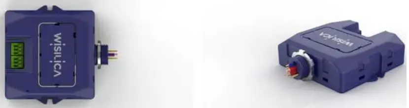 Radar AR10
Radar AR10 Bluetooth 5.2 Controllable Dual Channel 0-10V Room Controller
Radar AR10 is a BLE5.2 controllable, dual-channel 0-10V room controller. The device is powered by 277VAC voltage, also has a 20A relay to use it as a room controller or as a plug-load controller. It comes with Class-1 and Class-2 dual channel 0-10V dimming outputs, 0-10V sensor input, and 12V auxiliary output. The high output ratings within the device makes it suitable to control multiple numbers of light fixtures within a room. The device comes with 150mm external wire antenna for communication.
The Lumos Controls ecosystem comprises controllers, sensors, switches, modules, drivers, gateways, and analytical dashboards, and can be connected to the Lumos Controls cloud for data analytics and configuration management. The lighting network’s configuration, commissioning, and controlling can be done super-quick from any mobile device. The ecosystem is listed by the Design Lights Consortium (DLC), qualifying it for energy conservation incentive programs and rebates utility companies in North America.
Features
- Dual channel 0-10V independent output to control intensity and color temperature (CCT).
- Load control up to 20A @ 120/277VAC.
- Auxiliary 12V/100mA output to power the sensors.
- 0-10 VDC input channel to integrate with third party sensors.
- Class-1 and Class-2 dual channel 0-10V outputs to control the dimming and CCT.
- It acts as a Plug load controller to manage, control and monitor the plug loads efficiently.
- Instantaneous current and voltage measurement of connected load.
- BLE5.2 based non-flooding intelligent communication.
- Standard ½ inch chase nipple allows easy mounting to a junction box.
- Zero downtime Over-the-Air (OTA) firmware updates.
Specifications
| Electrical | Value | Remarks |
| Input Voltage | 120 – 277 VAC | |
| Input Current | 40 Ma @230 | 75 Ma @ 110v |
| Frequency | 50 – 60 Hz | |
| Load Voltage | 90-277 V | |
| Load Current | 20A | |
| Max LOAD output wattage | 5 KW | |
| Inrush current | 4A | |
| Surge protection | 4 kV | |
| Standby current | 14 Ma @ 110v | 12 Ma @ 230 V |
| 0-10V Output | Value | Remarks |
| Number of channels | 2 | |
| Voltage range | 0-10VDC | Tolerance: ±0.2V |
| Current | 100mA | Source current per channel |
| Dimming Range | 0-100% | 1000 steps resolution |
| Dimming curve | linear (default) /logarithmic |
| Sensor Input | Value | Remarks |
| Voltage Range | 0-10VDC Analog input |
| Auxiliary Output | Value | Remarks |
| Voltage | 12VDC | |
| Current | 100mA |
| Bluetooth | Value | Remarks |
| Frequency | 2402-2480 MHz | |
| Max output power | 8 dBm | |
| Receive sensitivity | -95 dBm | |
| Connection distance (device to device) | 45m (146 ft) | vary depending on the installation environment |
| Environmental | Value | Remarks |
| Operating temperature (in °C, °F) | -20 – 50 ºC | |
| Case temperature (in °C, °F) | 70 ºC | |
| Relative humidity (in °C, °F) | 20 – 85 % |
| Mechanical | Value | Remarks |
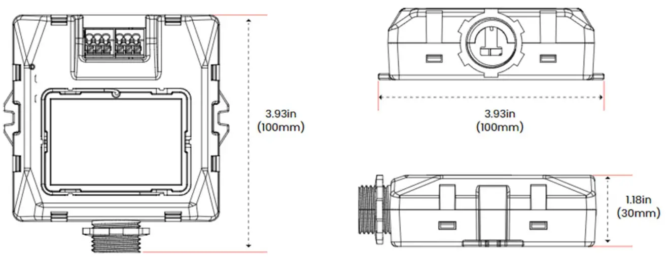
| Dimensions | 109.5 x 96.5 x 28 mm | L x W x H |
| Dimensions | 4.3 x 3.8 x 1.10 inch | L x W x H |
| Weight (in gm, oz) | 160 gm (2.11 oz) | |
| Case material | ABS Plastic (Blue color) | |
| Flammability rating | UL 94 5VA |
Dimensions
Radar AR10
Wire Description
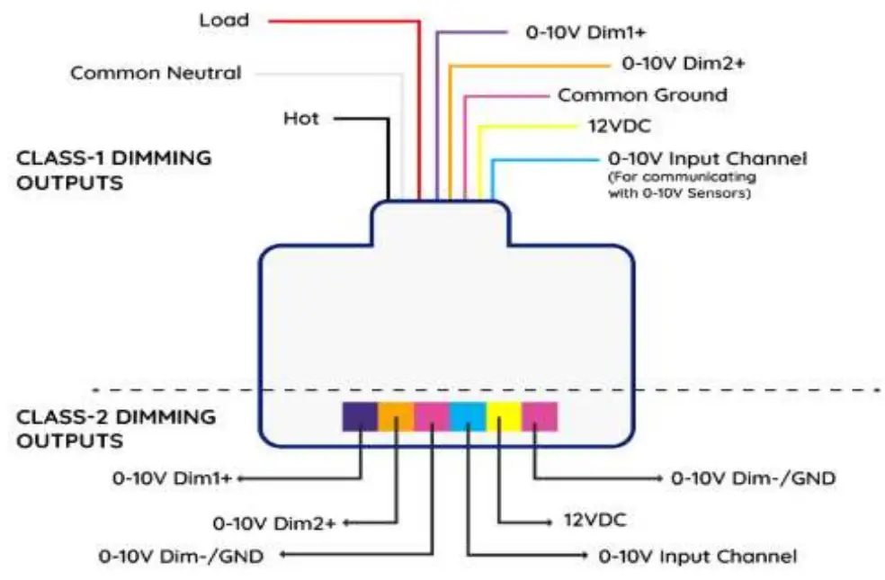
Class-1 outputs
| Pin | Name | Color | Gurage | Rating | Description |
| 1 | Line | Black | 12AWG (4.0mm2) | 600V | 120-277VAC |
| 2 | Common Neutral | White | 12AWG (4.0mm2) | 600V | 120-277VAC |
| 3 | Load | Red | 14AWG (2.5 mm2) | 600V | 120-277VAC |
| 4 | 0-10V DIM1+ | Purple | 20AWG (0.5mm2) | 600V | 0-10VDC/100mA |
| 5 | 0-10V DIM2+ | Orange | 20AWG (0.5mm2) | 600V | 0-10VDC/100mA |
| 6 | 0-10VDIM-/GND | Pink | 20AWG (0.5mm2) | 600V | 0-10VDC/GND |
| 7 | 12VDC | Yellow | 20AWG (0.5mm2) | 600V | 12VDC/100mA |
| 8 | 0-10VDC sensor input | Blue | 20AWG (0.5mm2) | 600V | 0-10VDC/2mA |
Class-2 Outputs
| Pin | Name | Push-in connector Color | Description |
| 1 | 0-10V DIM1+ | Purple | 0-10VDC/100mA |
| 2 | 0-10V DIM2+ | Orange | 0-10VDC/100mA |
| 3 | 0-10VDIM-/GND | Pink | 0-10VDC/GND |
| 4 | 0-10VDC sensor input | Blue | 0-10VDC/2mA |
| 5 | 12VDC | Yellow | 12VDC/100mA |
| 6 | 0-10VDIM-/GND | Pink | 0-10VDC/GND |
Antenna Information
150mm wire antenna
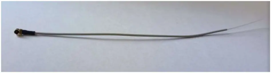
Antenna Properties | |
| Frequency range | 2.4 GHz-2.5GHz |
| Impedance | 50 Ω Nominal |
| VSWR | 1.92:1 Max |
| Return loss | -10 dB Max |
| Gain(peak) | 2 dB |
| Cable loss | 0.3 dB Max |
| Polarization | Linear vertical |
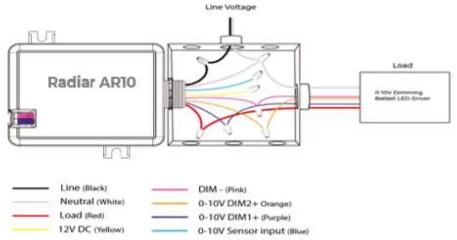
Wiring Types
Class-1 wiring
- In Class-1 wiring, the 0-10V low voltage control wires run along with the line voltage wires in a same conduit. (See the image below)
- Class 1 installations require wire with insulation that is rated for the voltage carried (most wiring has 600V rated insulation) and must be installed in conduit or a protective cable assembly.
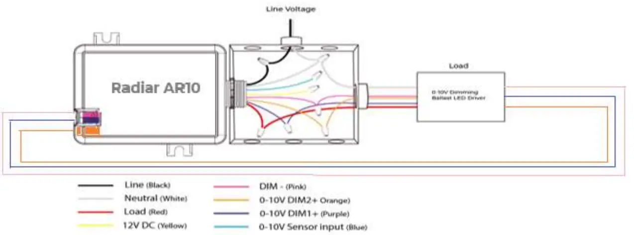
Class-2 wiring
- In Class-2 wiring, the 0-10V low voltage wires run separately in another conduit (See the image below)
- These circuits do not have high enough voltage or current to present a hazard to personnel and have less stringent installation requirements in regards to protection of the wiring.
- A Class 2 wiring may be installed free within the wall or ceiling without line voltage rated insulation or protection of conduit or a cable assembly.
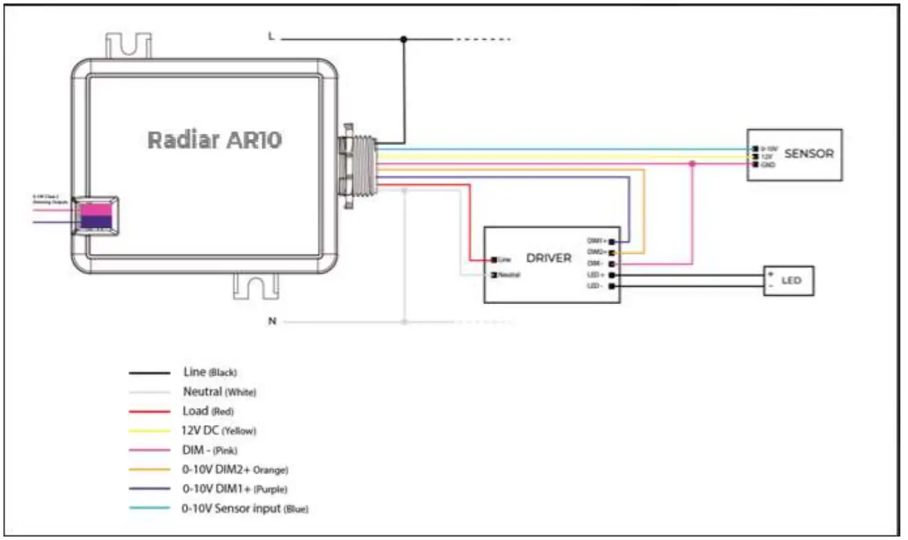
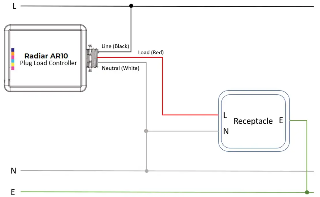
Wiring Diagram
- Configuring Radar AR10 for dimming, tuning and an external sensor control.

- Configuring Radar AR10 for Plug Load Control

Items included in the package box
- Radar AR10
- User Manual
- Antenna
Ordering Information
| Product Code | Product Description | Communication | Voltage Rating | Sensor Input | Output Channel | Aux Power | Relay Control | Inbuilt Power Measurement |
| WCA2CSRN | Wireless 0-10V dual channel dimming AC powered room controller without Power measurement. | BLE5.2 | 120-277V AC | 0-10 VDC | 0-10V 2 Channels | 12VDC | 20A | No |
| WCA2CSRN P | Wireless 0-10V dual channel dimming AC powered room controller Measurement. | BLE5.2 | 120-277V AC | 0-10 VDC | 0-10V 2 Channels | 12VDC | 20A | Yes |
FCC Statement
This equipment has been tested and found to comply with the limits for a Class B digital device, pursuant to part 15 of the FCC Rules. These limits are designed to provide reasonable protection against harmful interference in a residential installation. This equipment generates, uses and can radiate radio frequency energy and, if not installed and used in accordance with the instructions, may cause harmful interference to radio communications. However, there is no guarantee that interference will not occur in a particular installation. If this equipment does cause harmful interference to radio or television reception, which can be determined by turning the equipment off and on, the
user is encouraged to try to correct the interference by one or more of the following measures:
- Reorient or relocate the receiving antenna.
- Increase the separation between the equipment and receiver.
- Connect the equipment into an outlet on a circuit different from that to which the receiver is connected.
- Consult the dealer or an experienced radio/TV technician for help.
Caution: Any changes or modifications to this device not explicitly approved by manufacturer could void your authority to operate this equipment.
This device complies with part 15 of the FCC Rules. Operation is subject to the following two conditions:
(1) This device may not cause harmful interference, and
(2) this device must accept any interference received, including interference that may cause undesired operation.
RF Exposure Information
This equipment complies with FCC radiation exposure limits set forth for an uncontrolled environment. This equipment should be installed and operated with minimum distance
20cm between the radiator and your body.
![]() CONNECTING THINGS TO LIFE
CONNECTING THINGS TO LIFE
WI Silica Inc
23282 Mill Creek Dr #340, Laguna Hills, CA 92653 United States of America
[email protected] www.wisilica.com![]() www.wisilica.com
www.wisilica.com![]() [email protected]
[email protected]


