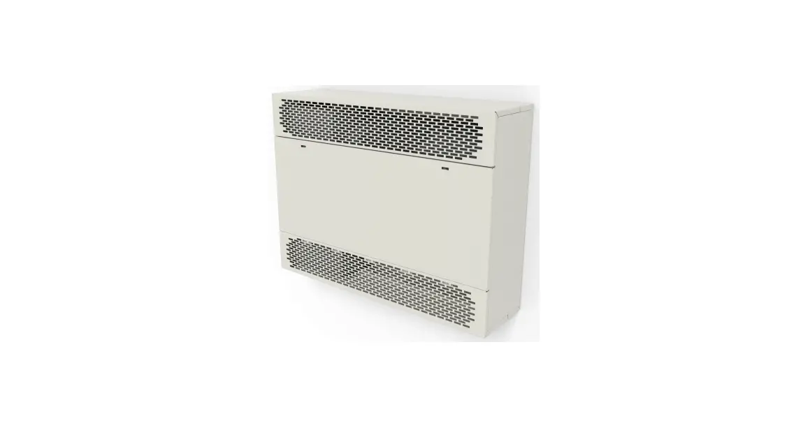
MARLEY 900 Series Cabinet Unit Heaters Instruction Manual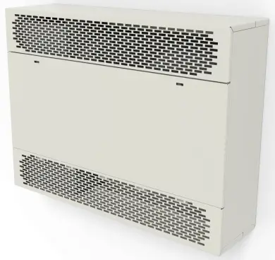
Dear Owner,
Congratulations! Thank you for purchasing this new heater manufactured by Marley Engineered Pruducts.
You have made a wise investment selecting the highest quality product in the heating industry. Please carefully read and follow the installation and maintenance directions shown in this manual. You should enjoy years of efficient heating comfort with this product from Marley Engineered Products… the industry’s leader in design, manufacturing, quality and service.
…The Employees of
Marley Engineered Products
![]() WARNING
WARNING ![]()
Read carefully – These instructions are written to help you prevent difficulties that might arise during installation of heaters. Studying the instructions first may save you considerable time and money later. Observe the following procedures and cut your installation time to a minimum.
TO REDUCE RISK OF FIRE AND ELECTRIC SHOCK:
- Disconnect all power coming to the heater at main service panel before wiring or servicing.
Note: More than one disconnect may be required. - All wiring must be in accordance with national and local electric codes and the heater must be grounded.
- Verify the power supply voltage coming to heater matches the ratings printed on the heater nameplate before energizing.
- This heater is hot when in use. To avoid burns, do not let bare skin touch hot surfaces.
- Do not insert or allow foreign objects to enter any ventilation or exhaust opening as this may cause electric shock, fire, or damage to heater.
- Do not block air intakes or exhaust in any manner.
Keep combustible materials at least 24” (610 mm) away from heater. Keep drapes at least 6” (153 mm) above top of front discharge grille. Do not use drapes above top discharge units. Do not install behind doors, furniture, towel rack, or boxes. - A heater has hot and arcing (sparking) parts inside.
Do not use in areas where gasoline, paint, or flammable liquids are used or stored. - Use this heater only as described in this manual. Any other use not recommended by the manufacturer may cause fire, electric shock, or injury.
- This heater is not approved for use in corrosive atmospheres such as marine, green house, or chemical storage areas.
- FOR DUCT CONNECTED HEATERS, Do not exceed 0.2” wg. external static pressure and do not mount heater on end panels.
SAVE THESE INSTRUCTION SHEETS
SPECIFICATIONS
| HEATING CAPACITY KW BTU/hr |
Series | Cabinet Length (in) |
CFM* | Total Line Amperage (includes motor amps) | ||||||
| 208 1 ph 60 Hz | 208 3 ph 60 Hz | 240 1 ph 60 Hz | 240 3 ph 60 Hz | 277 1 ph 60 Hz | 480 3 ph 60 Hz | |||||
| 2 | 6,826 | 10 | 6 | 9 | 6 | 8 | 3 | |||
| 3 | 10,239 | 15 | 9 | 13 | 8 | 12 | 4 | |||
| 4 | 13,652 | 20 | 12 | 17 | 10 | 15 | 6 | |||
| 5 | 17,065 | 935 | 35 | 250 | 25 | 15 | 22 | 13 | 19 | 7 |
| 6 | 20,478 | 30 | 17 | 26 | 15 | 22 | 8 | |||
| 7 | 23,891 | 34 | 20 | 30 | 18 | 26 | 9 | |||
| 8 | 27,304 | 39 | 23 | 34 | 20 | 30 | 10 | |||
| 4 | 13,652 | 20 | 12 | 18 | 11 | 16 | 6 | |||
| 6 | 20,478 | 30 | 18 | 26 | 16 | 23 | 8 | |||
| 8 | 27,304 | 40 | 23 | 34 | 20 | 30 | 11 | |||
| 10 | 34,130 | 48 | 29 | 43 | 25 | 37 | 13 | |||
| 12 | 40,956 | 945 | 45 | 500 | 59† | 34 | 51† | 30 | 44 | 16 |
| 14 | 47,785 | 68† | 40 | 59† | 35 | 52† | 18 | |||
| 16 | 54,608 | 78† | 46 | 68† | 40 | 59† | 20 | |||
| 6 | 20,478 | 31 | 19 | 27 | 16 | 24 | 9 | |||
| 9 | 30,717 | 45 | 27 | 39 | 24 | 34 | 13 | |||
| 12 | 40,956 | 60 | 35 | 52† | 31 | 45 | 16 | |||
| 15 | 51,195 | 968 | 68 | 750 | 74 | 44 | 64† | 38 | 56† | 20 |
| 18 | 61,434 | 88 | 52† | 77† | 45 | 67† | 24 | |||
| 21 | 71,673 | n/a | 60† | 89† | 52† | 78† | 27 | |||
| 24 | 81,912 | n/a | 69† | n/a | 60† | n/a | 31 | |||
| 8 | 27,304 | 41 | 24 | 36 | 21 | 31 | 12 | |||
| 12 | 40,956 | 60† | 36 | 52† | 31 | 46 | 17 | |||
| 16 | 54,608 | 79† | 47 | 69† | 41 | 60† | 21 | |||
| 20 | 68,260 | 978 | 78 | 1,000 | n/a | 58† | 86† | 50† | 74† | 26 |
| 24 | 81,912 | n/a | 69† | n/a | 60† | n/a | 31 | |||
| 28 | 95,564 | n/a | 80† | n/a | 70† | n/a | 36 | |||
| 32 | 109,216 | n/a | 91† | n/a | 79† | n/a | 41 | |||
| † – CIRCUIT BREAKERS or FUSED DISCONNECT required * – Value shown for HIGH SPEED on two speed units | ||||||||||
General Information
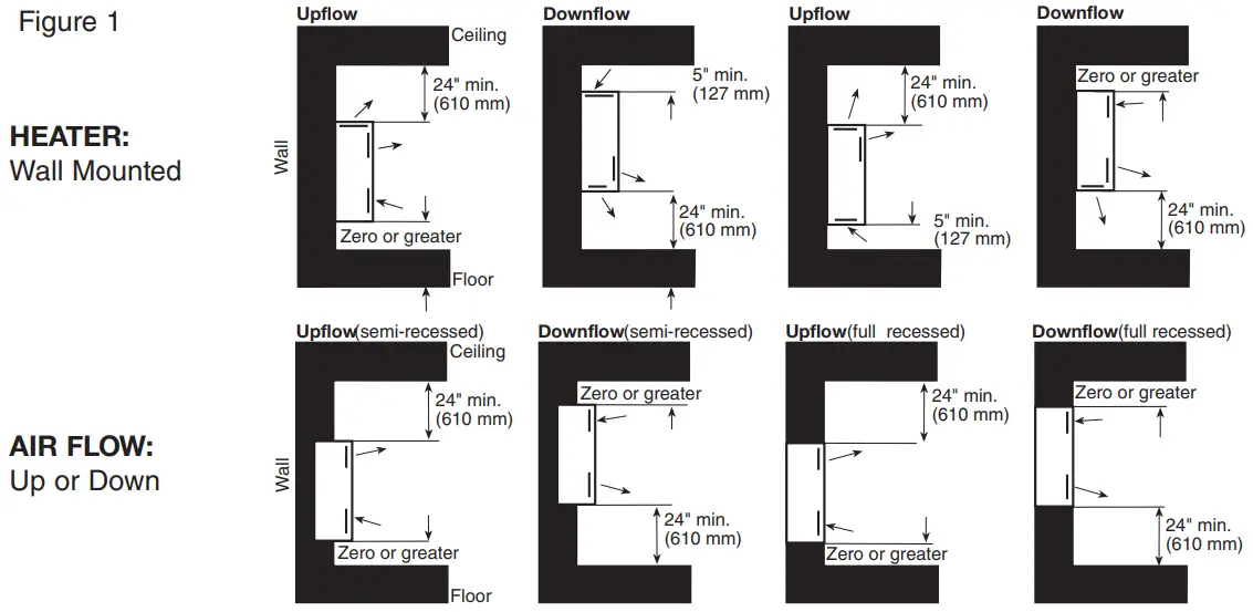
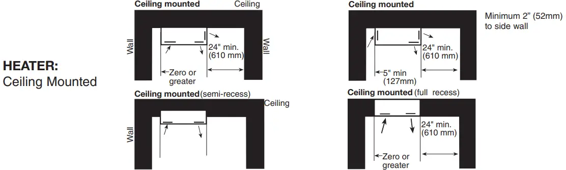
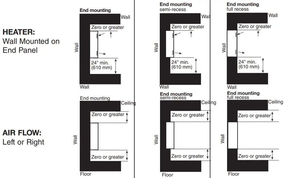
900 Series Cabinet Unit Heaters are designed and UL & cUL Listed to be applied as Standard Free Air heaters with both grille and louvered intake and discharge panels for recess or surface installation: a) on the floor, with front inlet and up flow air movement in the up flow, down flow, left or right direction or b) on the ceiling, or Ducted (0.2″ wg external static pressure) flange for direct connection of field supplied ductwork to the inlet, discharge, or both inlet and discharge. Ducted heaters can be installed for recess or surface installation: a) on the floor, with front inlet and up flow air movement, b) on the wall, with air movement in the up flow or down flow direction or c) on the ceiling. See Figure 1 for Mounting Clearances.
Note: Keep all furniture or any other blocking material at least 24″ (610mm) away from front of heater. When draperies are used, hang them so that when in use they are at least 6″ (153mm) above the top of front discharge heater. Do not use draperies with top discharge heaters. See Figure 2 for Mounting Dimensions See Figure 3 for Duct Collar Dimensions and Installation Details.
FLOOR MOUNTING
- Heaters with front inlet and up flow air movement may be mounted directly on any floor surface including carpeting. Where wall to wall carpeting is installed after heater installation, the carpeting can be run up to the front and around the heater’s body. See Figure 1 for mounting clearances.
- Heaters can be mounted on either end with air movement left or right directly on any floor surface including carpeting. See Figure 1 for mounting clearances.
- If optional kick plate is not used, proceed to “HEAT INSTALLATION” section.
INSTALLATION
INSTALLATION OF OPTIONAL 900 SERIES BASE KIT
- If desired, the heaters may be mounted off the floor with optional kick plate panel.
- Align panel on bottom of heater (Inlet side Only)
- There should be a 1″ (25mm) space from the panel to the front and sides of the heater.
- Match drill .140″ (3.55 mm) diameter holes in the bottom of the heater and secure with screws provided. 5. Proceed to “HEATER INSTALLATION” section.
![]() CAUTION
CAUTION
TO PREVENT HEATER FROM FALLING AND CAUSING PERSONAL INJURY, EACH FASTENER, AS APPLIED, SHOULD HAVE THE HOLDING POWER OF AT LEAST 100 POUNDS (45 kg).
WALL OR CEILING RECESS MOUNTING
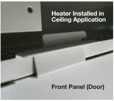
Note: Your heater has design provisions to keep your front panel secured when used in ceiling applications. This will allow the front panel to swing down and hang in place attached to the unit, out of the way when servicing the unit.
The front panels remain secured by a slide and pull design on the hinges. To remove it, simply slide the panel to the left and pull down.
- Create an opening in the wall 26-5/8″ (676mm) high by the length of the heater plus 1/4″ (6.4mm). Example: If the heater was 68 inches long, the opening should measure 26-5/8″ high x 68-1/4″ long).
- The depth of the recess will vary with the desired amount of heater recess.
- Proceed to “HEATER INSTALLATION” section.
INSTALLATION OF OPTIONAL 900 SERIES RECESS TRIM KIT
- Determine depth of heater recess.
- Align recess trim frame so that the trim frame front edge will touch wall when heater is installed.
- Match drill .140″ (3.55mm) diameter holes in all four sides the heater and secure trim frame with screws provided.
- Proceed to “HEATER INSTALLATION” section.
HEATER INSTALLATION
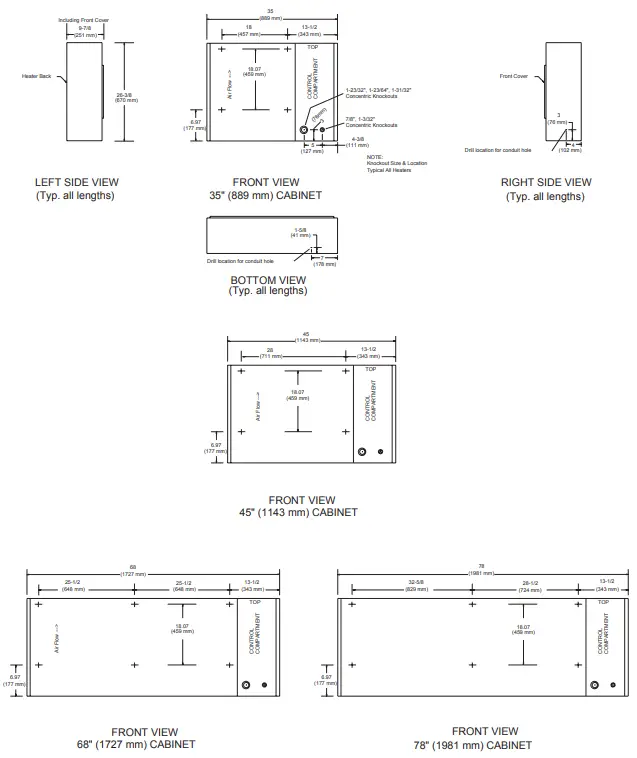
- Rough-in electrical wiring. See Figure 2 for knockout location
- Remove the proper knockout in the heater or punch the proper size hole in the bottom or right side of the heater as shown in Figure 2.
- Remove the front cover by rotating the lock(s) counter-clockwise (ccw).
- Remove both grilles or louvered discharge panels by removing 2 screws (1 on each end) that attach the grille or louvered panel to the end panels.
- Refer to Figure 2 for location of mounting holes.
- Mark and drill holes for heater attachment in wall or ceiling.
- Install heater in opening and tighten screws (field supplied) to secure tight fit of the heater against the mounting surface
NOTE: Tightening the heater against an irregular wall will cause distortion of the back panel of the heater. If this is the case, shims should be used behind the back panel to keep it straight. - Reinstall the grille or louver panel by sliding the panel into the heater. Position the panel tabs of the grille or louver panel to rest on the top of the lip of the heater back.
Position the grille or louver panel top even with the top of the end panels. Tap the grille or louver panel at the top front (both sides) to seat the panel. Reinstall 2 screws (one on each side) that attach grille or louver panel to the end panels. - WIRING – See wiring section on page 8.
- After wiring is complete, insure that the control box cover is closed and fastened and that the filter is installed.
- Adjust the thermostat to the desired set point.
- Adjust the heat selector to the heat and fan speed desired.
- Replace front cover and secure by turning the locks clockwise (cw) until tight. Replace plug buttons provided.
- Leave the heater running a few hours before making further change in thermostat setting.
DUCTED APPLICATIONS
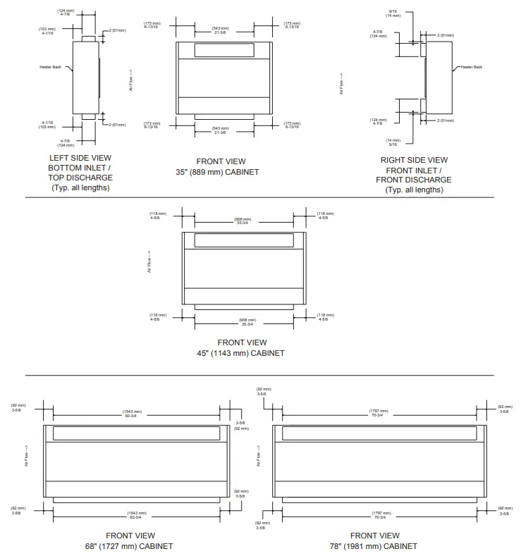
- See Figure 3 for duct flange size and location.
- Duct collars have been factory located (Bottom inlet, Front inlet, Top discharge, Front discharge) as ordered.
 WARNING
TO REDUCE RISK OF FIRE AND ELECTRICAL SHOCK: DO NOT EXCEED 0.2” WG EXTERNAL STATIC PRESSURE. DO NOT MOUNT HEATER ON END PANEL (LEFT OR RIGHT AIR FLOW). - To change duct collar location:
A. Heater duct panels are supplied with a duct collar attached to one surface and a blank-off plate attached to the other surface. The location of the duct collar and the blank-off plate can be reversed.
B. Remove screws holding blank-off plate and remove blank-off plate.
C. Remove screws holding duct collar and remove duct collar.
D. Position duct collar to location desired, align screw holes, insert and tighten screws to secure duct collar to duct panel.
E. Position blank-off plate to location desired, align screw holes, insert and tighten screws blank-off plate to duct panel. - Position field ductwork to outside of heater duct flange.
- Mark and drill starting holes in duct and flange.
- Install and tighten screws (field supplied) to provide a secure seal.
MOUNTING DIMENSIONS
DUCT COLLARS
DIMENSIONS and INSTALLATION DETAILS
WIRING
SEE WARNING STEPS 1, 2 & 3 ON PAGE 1 OF THIS INSTRUCTION SHEET.
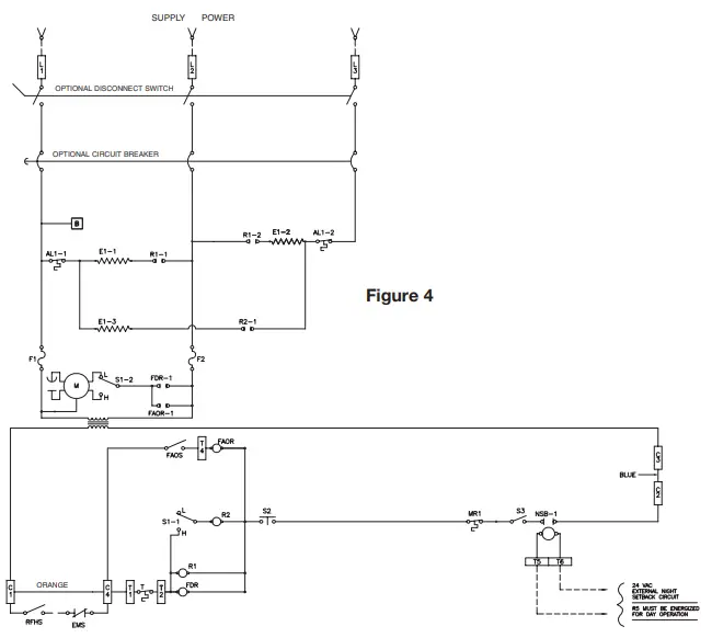
- Figure 4 shows a typical wiring diagram.
- For actual wiring, see the diagram located on the inside of the frr ont cover.
- All field wiring must be 75˚ C min.
TO CONVERT 208, 240, & 480 VOLT STANDARD STOCK 5 & 10 KW HEATERS From Three Phase to Single Phase
- Remove front cover.
- Refer to wiring diagram located located inside front cover.
NOTE: Terminal block and wires that need to be changed are located in wire way above right hand (RH) blower housing. - Remove two screws holding wireway cover to fan panel.
- Rotate wireway cover up and out to remove.
- Terminal block is located within wireway.
- Relocate wires per wiring diagram located inside front cover.
- Reinstall wireway cover and reinstall screws.
- Reinstall front cover.
EMS=ENERGY MANAGEMENT SYSTEM TIE-IN (CONTACTS MUST BE CLOSED FOR DAY OPERATION) RFHS=REMOTE MOUNTED FAN/HEAT ON-OFF SWITCH (FIELD SUPPLIED) NOTE: IF EMS AND/OR RFHS ARE INSTALLED REMOVE ORANGE WIRE BETWEEN C1 AND C4.
FOR EXTERNAL CONTROL SUPPLY:
- REMOVE BLUE JUMPER BETWEEN C2 AND C3.
- CONNECT EXTERNAL CONTROL (24 VAC STANDARD, 120 VAC OPTIONAL) TO C1 AND C2
S1 = FAN/HEAT HIGH-LOW SELECTOR SWITCH
S2 = DOOR INTERLOCK SWITCH
S3 = FAN/HEAT ON-OFF SWITCH (FACTORY INSTALLED OPTION)
NSB = NIGHT SETBACK RELAY (FACTORY INSTALLED OPTION)
AL = AUTO RESET LIMIT
MR = MANUAL RESET LIMIT
T = BUILT-IN OR REMOTE MOUNTED SINGLE POLE THERMOSTAT
FAOS = FAN AUTO-ON SWITCH (BUILT-IN = FACTORY INSTALLED OPTION)
(REMOTE MOUNTED = FIELD INSTALLED OPTION)
FDR = FAN DELAY RELAY
FAOR = FAN AUTO-ON RELAY (FACTORY INSTALLED OPTION)
CIRCUIT BREAKER PART NUMBERS
| CABINET LENGTH | KW | 208V 1 PH | 208V 3PH | 240V 1PH | 277V 1PH | 480V 3PH | |||||
| QTY | VAR | QYT | VAR | QTY | VAR | QTY | VAR | QTY | VAR | ||
|
35 in. | 2 | 1 | 41 | 1 | 50 | N/A | N/A | 1 | 78 | 1 | 82 |
| 3 | 1 | 42 | 1 | 50 | 1 | 42 | 1 | 78 | 1 | 82 | |
| 4 | 1 | 43 | 1 | 50 | 1 | 43 | 1 | 79 | 1 | 82 | |
| 5 | 1 | 45 | 1 | 51 | 1 | 44 | 1 | 79 | 1 | 82 | |
| 6 | 1 | 46 | 1 | 52 | N/A | N/A | 1 | 80 | 1 | 82 | |
| 8 | 1 | 48 | 1 | 53 | 1 | 47 | 1 | 81 | 1 | 82 | |
|
45 in. | 4 | 1 | 44 | 1 | 50 | N/A | N/A | 1 | 79 | 1 | 82 |
| 6 | 1 | 46 | 1 | 52 | N/A | N/A | 1 | 80 | 1 | 82 | |
| 8 | 1 | 48 | 1 | 53 | N/A | N/A | 1 | 81 | 1 | 82 | |
| 10 | 1 | 49 | 1 | 55 | N/A | N/A | 1 | 81 | 1 | 83 | |
| 12 | N/A | N/A | 1 | 56 | N/A | N/A | N/A | N/A | 1 | 83 | |
| 14 | N/A | N/A | 1 | 57 | N/A | N/A | N/A | N/A | 1 | 84 | |
| 16 | N/A | N/A | 1 | 58 | N/A | N/A | N/A | N/A | 1 | 84 | |
| 58 in. | 8 | N/A | N/A | 1 | 53 | N/A | N/A | N/A | N/A | 1 | 82 |
| 10 | 1 | 49 | N/A | N/A | N/A | N/A | N/A | N/A | N/A | N/A | |
| 12 | N/A | N/A | N/A | N/A | N/A | N/A | N/A | N/A | 1 | 83 | |
| 16 | N/A | N/A | N/A | N/A | N/A | N/A | N/A | N/A | 1 | 84 | |
| 68 in. | 12 | N/A | N/A | N/A | N/A | N/A | N/A | N/A | N/A | 1 | 83 |
| 15 | N/A | N/A | N/A | N/A | N/A | N/A | N/A | N/A | 1 | 84 | |
| 18 | N/A | N/A | N/A | N/A | N/A | N/A | N/A | N/A | 1 | 85 | |
| 21 | N/A | N/A | N/A | N/A | N/A | N/A | N/A | N/A | 1 | 91 | |
| 24 | N/A | N/A | N/A | N/A | N/A | N/A | N/A | N/A | 1 | 70 | |
| 78 in. | 20 | N/A | N/A | N/A | N/A | N/A | N/A | N/A | N/A | 1 | 91 |
| 24 | N/A | N/A | N/A | N/A | N/A | N/A | N/A | N/A | 1 | 70 | |
| 28 | N/A | N/A | N/A | N/A | N/A | N/A | N/A | N/A | 1 | 71 | |
| 32 | N/A | N/A | N/A | N/A | N/A | N/A | N/A | N/A | 1 | 72 | |
ELEMENTS/ORDER PART NO. 1802-2083 + VAR NOTED BELOW
| CABINET LENGTH | KW | 208 1 PH 60HZ | 208 3PH 60HZ | 240 1PH 60HZ | 240 3PH 60HZ | 277 1PH 60HZ | 480 3PH 60HZ | ||||||
| QTY | VAR | QTY | VAR | QTY | VAR | QTY | VAR | QTY | VAR | QTY | VAR | ||
|
35 in. | 2 | 1 | 100 | 1 | 100 | 1 | 101 | 1 | 101 | 1 | 114 | 1 | 114 |
| 3 | 1 | 107 | 1 | 107 | 1 | 114 | 1 | 114 | 1 | 116 | 1 | 116 | |
| 4 | 1 | 106 | 1 | 106 | 1 | 107 | 1 | 107 | 1 | 108 | 1 | 108 | |
| 5 | 1 | 110 | 1 | 110 | 1 | 111 | 1 | 111 | 1 | 120 | 1 | 120 | |
| 6 | 2 | 107 | 2 | 107 | 2 | 108 | 2 | 108 | 2 | 116 | 2 | 116 | |
| 7 | 1 1 | 107 106 | 1 1 | 107 106 | 1 1 | 108 107 | 1 1 | 108 107 | 1 1 | 116 108 | 1 1 | 116 108 | |
| 8 | 1 1 | 107 110 | 1 1 | 107 110 | 1 1 | 108 111 | 1 1 | 108 111 | 1 1 | 120 120 | 1 1 | 120 120 | |
|
45 in. | 4 | 2 | 100 | 2 | 100 | 2 | 101 | 2 | 101 | 2 | 114 | 2 | 114 |
| 6 | 2 | 107 | 2 | 107 | 2 | 108 | 2 | 108 | 2 | 116 | 2 | 116 | |
| 8 | 2 | 106 | 2 | 106 | 2 | 107 | 2 | 107 | 2 | 108 | 2 | 108 | |
| 10 | 2 | 110 | 2 | 110 | 2 | 111 | 2 | 111 | 2 | 120 | 2 | 120 | |
| 12 | 4 | 107 | 4 | 107 | 4 | 108 | 4 | 108 | 4 | 116 | 4 | 116 | |
| 14 | 2 2 | 107 106 | 2 2 | 107 106 | 2 2 | 08 107 | 2 2 | 108 107 | 2 2 | 116 108 | 2 2 | 116 108 | |
| 16 | 2 2 | 107 110 | 2 2 | 107 110 | 2 2 | 108 111 | 2 2 | 108 111 | 2 2 | 116 120 | 2 2 | 116 120 | |
| 68 in. | 21 | N/A | N/A | 3 3 | 107 106 | 3 3 | 108 107 | 3 3 | 108 108 | 3 3 | 116 108 | 3 3 | 116 108 |
| 24 | N/A | N/A | 3 3 | 107 110 | N/A | N/A | 3 3 | 108 111 | N/A | N/A | 3 3 | 116 120 | |
| 78 in. | 20 | N/A | N/A | 4 | 110 | 4 | 111 | 4 | 111 | 4 | 120 | 4 | 120 |
| 24 | N/A | N/A | 8 | 107 | N/A | N/A | 8 | 108 | N/A | N/A | 8 | 116 | |
| 28 | N/A | N/A | 4 4 | 107 106 | N/A 4 | N/A | 4 | 108 107 | N/A 4 | N/A | 4 4 | 116 108 | |
| 32 | N/A | N/A | 4 4 | 107 110 | N/A | N/A | 4 4 | 108 111 | N/A | N/A | 4 4 | 116 120 | |
REPLACEMENT PARTS LIST
Basic Model Series
| CU900 Model Series | |||||||||
| Part Description | 935 | 945 | 968 | 978 | |||||
| QTY | P/N | QTY | P/N | QTY | P/N | QTY | P/N | ||
| Filter (Permanent) | 1 | 2010-7008-006 | 1 | 2010-7008-007 | 1 | 2010-7008-006 | 2 | 2010-7008-007 | |
| 1 | 2010-7008-007 | ||||||||
| Filter (Throw-Away) | 1 | 2010-7008-006 | 1 | 2010-7008-007 | 1 | 2010-7009-006 | 2 | 2010-7009-007 | |
| 1 | 2010-7009-007 | ||||||||
|
Motor | Standard Heaters | 1 | 3900-2032-000 | 1 | 3900-2033-000 | 1 | 3900-2033-000 | 2 | 3900-2033-000 |
| 1 | 3900-2032-000 | ||||||||
| 277V Heaters | 1 | 3900-2032-001 | 1 | 3900-2033-001 | 1 | 3900-2033-001 | 2 | 3900-2033-001 | |
| 1 | 3900-2032-001 | ||||||||
| 480V Heaters | 1 | 3900-2032-002 | 1 | 3900-2033-002 | 1 | 3900-2033-002 | 2 | 3900-2033-002 | |
| 1 | 3900-2032-002 | ||||||||
| Manual Reset Limit | 1 | 4520-2017-003 | 1 | 4520-2017-003 | 1 | 4520-2017-001 | 1 | 4520-2017-001 | |
| Auto Reset Limit | 4520-2048-000 | ||||||||
| Power Relay | 24V Control | 410101001 | |||||||
| 120V Control | 410101003 | ||||||||
|
Fan Delay Relay | Single Stage 24V Control | 410171001 | |||||||
| Single Stage 120V Control | 410171002 | ||||||||
| Two Stage 24V Control | 410101001 | ||||||||
| Two Stage 120V Control | 410101003 | ||||||||
| Transformer (Control) | 24V Control | 490026007 | |||||||
| 120V Control | 490026004 | ||||||||
| Non-Convertible Heaters Transformer (Control) | 24V Control | 490026009 | |||||||
| 120V Control | 490026010 | ||||||||
| Thermostat (Built-In) | Single Stage Heater | 410127001 | |||||||
| Two Stage Heater | 5813-2008-000 | ||||||||
| Fan/Heat High-Low Switch | 5216-2029-000 | ||||||||
| Fan/Heat On-Off Switch | 5216-2029-001 | ||||||||
| Smart Digital Controller | 1414-11050-000 | ||||||||
CUHS REPLACEMENT PARTS
CUHS 900 Series Element Part Numbers
| Stocked Models | 208V | 240V | 227V | 480V | ||||
| Qty. | Part Number | Qty. | Part Number | Qty. | Part Number | Qty. | Part Number | |
| 935 5KW | 1 | 1802-2083-110 | 1 | 1802-2083-111 | 1 | 1802-2083-120 | 1 | 1802-2083-120 |
| 945 10KW | 2 | 1802-2083-110 | 2 | 1802-2083-111 | 2 | 1802-2083-120 | 2 | 1802-2083-120 |
CUHS 900 Series Motor Part Numbers
| Stocked Models | 208V | 240V | 227V | 480V | ||||
| Qty. | Part Number | Qty. | Part Number | Qty. | Part Number | Qty. | Part Number | |
| 935 5KW | 1 | 3900-2032-000 | 1 | 3900-2032-000 | 1 | 3900-2032-000 | 1 | 3900-2032-000 |
| 945 10KW | 1 | 3900-2033-000 | 1 | 3900-2033-000 | 1 | 3900-2033-000 | 1 | 3900-2033-000 |
| 935NC 5KW | N/A | N/A | 1 | 3900-2032-001 | 1 | 3900-2032-002 | ||
| 945NC 10KW | N/A | N/A | 1 | 3900-2033-001 | 1 | 3900-2033-002 | ||
CUHS 900 Series Common Parts for All Heaters
| Description | Part Number | |
| Model 935 Model 945 | ||
| Front Cover | 4513-11060-000 | 4513-11060-001 |
| Louver Panel | 2501-11040-000 | 2501-11040-001 |
| Filter (Permanent) | 2010-7008-006 | 2010-7008-007 |
| Filter (Throw Away) | 2010-7009-006 | 2010-7008-007 |
| Front Cover Interlock Switch | 5216-2028-000 | |
| Front Cover Lock-Screw Slot | 3500-2000-000 | |
| End Panel | 1800-2050-000 | |
| Blower Wheel | 490047001 | |
| Motor Fuse | 481001017 | |
| Auto Reset Limit | 4520-2048-000 | |
| Manual Reset | 4520-2017-003 | |
| Fan/Heat Hi-Low Switch | 5216-2029-001 | |
| Fan/Heat On-Off Switch | 5216-2029-001 | |
| Thermostat (SPST) | 410127001 | |
| Thermostat Knob | 3301-2020-001 | |
| Time Delay Relay (SPST 24V) | 410171001 | |
| Time Delay Relay (DPST 24V) | 410101001 | |
| Power Transformer 480V | 490015025 | |
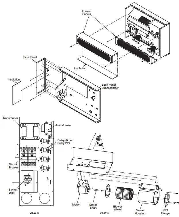
EXPLODED VIEWS
LIMITED WARRANTY
All products manufactured by Marley Engineered Products are warranted against defects in workmanship and materials for one year from date of installation, except heating elements which are warranted against defects in workmanship and materials for five years from date of installation. This warranty does not apply to damage from accident, misuse, or alteration; nor where the connected voltage is more than 5% above the nameplate voltage; nor to equipment improperly installed or wired or maintained in violation of the product’s installation instructions. All claims for warranty work must be accompanied by proof of the date of installation.
The customer shall be responsible for all costs incurred in the removal or reinstallation of products, including labor costs, and shipping costs incurred to return products. Within the limitations of this warranty, inoperative units should be returned to Marley Engineered
Products (see contact information below) and we will repair or replace, at our option, at no charge to you with return freight paid by
Marley. It is agreed that such repair or replacement is the exclusive remedy available from Marley Engineered Products.
THE ABOVE WARRANTIES ARE IN LIEU OF ALL OTHER WARRANTIES EXPRESSED OR IMPLIED, AND ALL IMPLIED WARRANTIES OF MERCHANTABILITY AND FITNESS FOR A PARTICULAR PURPOSE WHICH EXCEED THE AFORESAID EXPRESSED WARRANTIES ARE HEREBY DISCLAIMED AND EXCLUDED FROM THIS AGREEMENT. MARLEY ENGINEERED PRODUCTS SHALL NOT BE LIABLE FOR CONSEQUENTIAL DAMAGES ARISING WITH RESPECT TO THE PRODUCT, WHETHER BASED UPON NEGLIGENCE, TORT, STRICT LIABILITY, OR CONTRACT.
Some states do not allow the exclusion or limitation of incidental or consequential damages, so the above exclusion or limitation may not apply to you. This warranty gives you specific legal rights, and you may also have other rights which vary from state to state.
Contact Marley Engineered Products in Bennettsville, SC, at 1-800-642 4328. Merchandise returned to the factory must be accompanied by a return authorization and service identification tag, both available from Marley Engineered Products. When requesting return authorization, include all catalog numbers shown on the products.
HOW TO OBTAIN WARRANTY SERVICE AND WARRANTY PARTS PLUS GENERAL INFORMATION
- Warranty Service or Parts 1-800-642-4328
- Purchase Replacement Parts 1-800-654-3545
- General Product Information www.marleymep.com
Note: When obtaining service always have the following:
- Model number of the product
- Date of manufacture
- Part number or description


 Owner's Manual")


