
SPYKER P70-12010 36 Inch Professional Drop Spreader Owner’s Manual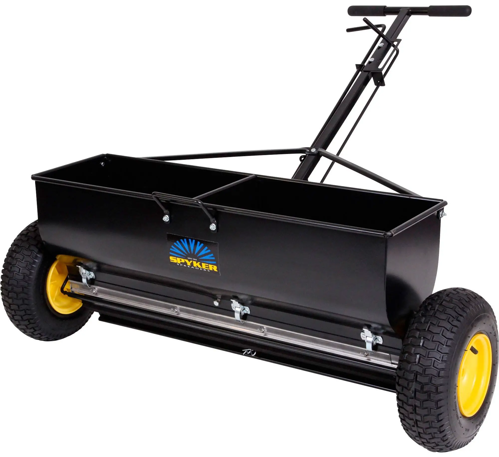
IMPORTANT
This manual contains information for the safety of persons and property. Read it carefully before assembly and operation of the equipment!
PARTS BREAKDOWN
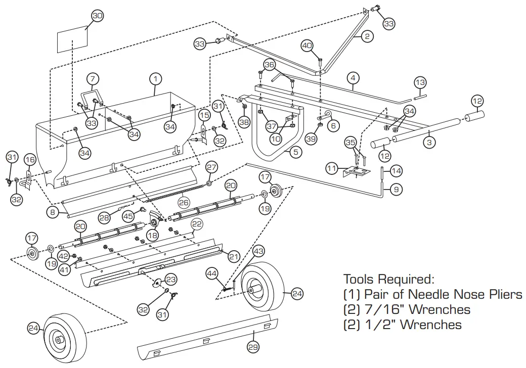
| ITEM | PART # | DESCRIPTION | QTY | ITEM | PART # | DESCRIPTION | QTY | ||
| 1 | N/A | Hopper Body (NOT OFFERED) | 1 | 23 | 017123 | Cam Gauge | 1 | ||
| 2 | 1009430 | Handle Brace | 1 | 24 | 1001607 | 13″ X 5″ Pneumatic Wheel | 2 | ||
| 3 | 1009431 | Handle | 1 | 26 | 017127 | #50 Sash Chain | 1 | ||
| 4 | 1009432 | Rate Adjustment Lever | 1 | 27 | 034392 | Key Ring | 1 | ||
| 5 | 1009433 | Parking Leg | 1 | 28 | H-529 | Hair Pin Cotter | 1 | ||
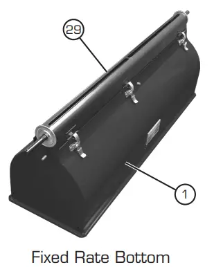
| 6 | 1009434 | Shutoff Lever Guide | 1 | 29 | 017129 | Fixed-Rate Bottom | 1 | ||
| 7 | 030952 | Lift Handle | 1 | 30 | 1009435 | Spyker Decal | 1 | ||
| 8 | 034394 | Spread Plate | 1 | 31 | 1003315 | 5/16″ Wingnut | 3 | ||
| 9 | 030882 | Spread Plate Shutoff Lever | 1 | 32 | 45M1111P | 5/16″ Washer | 3 | ||
| 10 | 092502 | Shutoff Guide | 1 | 33 | 1009436 | 1/4″-20 x 5/8″ Hex Bolt | 4 | ||
| 11 | 020148 | Lever Lock | 1 | 34 | 1004975 | 1/4″-20 Flange Nut | 6 | ||
| 12 | 092503 | Handle Grip | 2 | 35 | 11M0824P | 1/4″-20 x 1-1/2″ Carriage Bolt | 2 | ||
| 13 | 017114 | Shutoff Grip | 1 | 36 | 2M1040P | 5/16″-18 x 2-1/2″ Hex Bolt | 2 | ||
| 14 | 092504 | Lever Grip | 1 | 37 | B-4786 | 5/16″-18 Nylon Lock Nut | 2 | ||
| 15 | 030843 | End Bearing Retainer LH | 1 | 38 | 1009437 | 5/16″-18 Flange Nut | 1 | ||
| 16 | 030844 | End Bearing Retainer RH | 1 | 39 | B-4785 | 1/4″-20 Nylon Lock Nut | 1 | ||
| 17 | 017117 | End Bearing | 2 | 40 | 2M0828SS | 1/4″-20 x 1-3/4″ Hex Bolt | 1 | ||
| 18 | 017120 | Center Bearing | 1 | 41 | 1009438 | #10 Nylon Washer | 4 | ||
| 19 | 017118 | Rotor End Washer | 2 | 42 | 1001308 | #10-24 Nylon Locknut | 4 | ||
| 20 | 017119 | Rotor Bar | 2 | 43 44 | 1009468 | 0.172″ x 1.60″ Clevis Pin 7/64″ Cotter Pin | 2 | ||
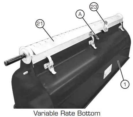
| 21 | 017122 | Variable Rate Bottom | 1 | ||||||
| 45 | 2M1008P | 5/16″-18 x 1/2″ Bolt | 1 | ||||||
| 22 | 017121 | Slide Hanger | 1 | ||||||
ASSEMBLY
- Place Hopper Body (1, Not Shown) upside down. Unsnap and remove Variable Rate Bottom (21, Not Shown) assembly.
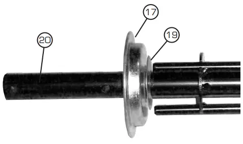
- Slide Rotor End Washer (19) and End Bearing (17) on end of Rotor Bar (20) as shown. Repeat for the other Rotor Bar (20).

- Install Rotor Bars (20) into Hopper Body (1), ensuring that the End Bearings (17) rest on the Hopper Body as shown.
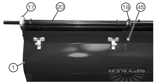
Turn the Rotor Bars (20) by hand. If one or more Rotor Bars are difficult to turn, loosen the 5/16″- 18 x 1/2″ Hex Bolt (45) and adjust the angle of the Center Bearing (18) until both Rotors Bars (20) rotate freely, and then tighten the 5/16″-18 x 1/2″ Hex Bolt (45) completely.
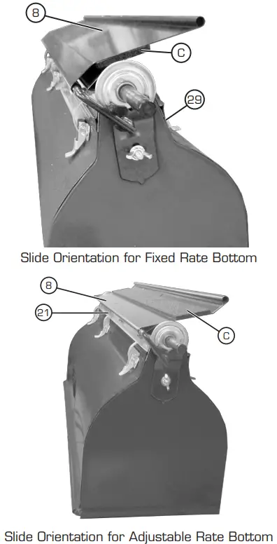
- Re-install bottom slide assembly. Note there are two bottom plates provided. One is a Variable Rate Bottom (21) slide assembly and one is a Fixed Rate Bottom (29) assembly. Variable Rate Bottom (21) slide assembly is shown to the right. Fixed Rate Bottom (29) assembly is shown below.

NOTE: Ensure Cam Gauge (23) on Variable Rate Bottom (21) slide is oriented as shown. It is on the same side of the Hopper Body (1) as the handle attachment stud (A).
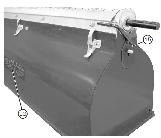
- Install End Bearing Retainer LH (15) as shown.
Note orientation in relationship to Spyker Decal (30).
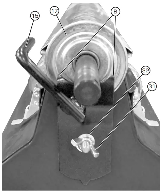
- Be sure the prongs (B) of the End Bearing Retainer LH (15) are centered on End Bearing (17) as shown. Secure using 5/16″ Washer (32) and 5/16″ Wingnut (31). Only install one End Bearing Retainer at this time. You will install the other one later.

- If you are using the Fixed Rate Bottom (29), install the Spread Plate (8) as shown ensuring the rubber pad (C) will contact the Fixed Rate Bottom. If using the Variable Rate Bottom (21), install the Spread Plate (8) the opposite way so the rubber pad (C) faces away from the Variable Rate Bottom (21).
NOTE: The orientation of the Spread Plate (8) must match the pictures exactly to ensure proper functionality during use. If the Spread
Plate (8) is installed using the incorrect hole, it will be impossible to shut off the flow of material when using the Fixed Rate Bottom (29), and the material will not “slide” off the Rate Plate (8) correctly when using the drop spreader. - Install the End Bearing Retainer RH (16, Not Shown) into the free end of the Spread Plate (8) and secure using 5/16″ Washer (32, Not Shown) and 5/16″ Wingnut (31, Not Shown).
Be sure the prongs of the End Bearing Retainer RH (16) are centered on End Bearing (17) (similarly to how it is shown in Step 6).
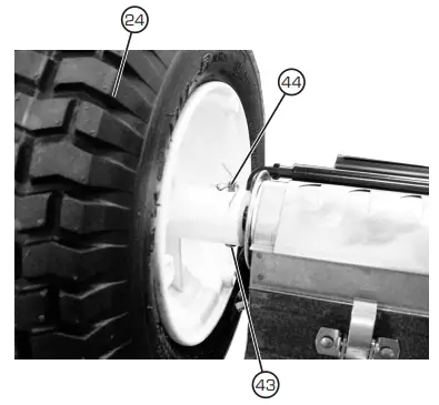
- Install Pneumatic Wheels (24) onto Rotor Bars (Not Shown) and secure with 0.172″ x 1.60″ Clevis Pin (43) and 7/64″ Cotter Pin (44). Use pliers to bend 7/64″ Cotter Pin (44) as shown.

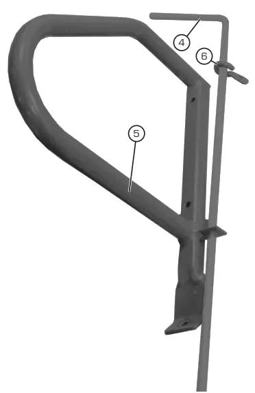
- Insert the Rate Adjustment Lever (4) into Parking Leg (5) flange as shown. Install Rate Adjustment Lever Guide (6) onto Rate Adjustment Lever (4).
NOTE orientation of Rate Adjustment Lever Guide (6). If you install it upside down, you will not be able to attach it to the Handle (3, Not Shown).
NOTE:
The Rate Adjustment Lever (4) has bends at both ends.
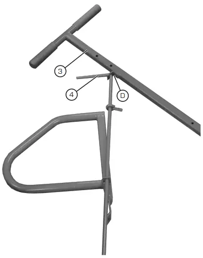
- Install Rate Adjustment Lever (4) through bracket (D) in Handle (3).

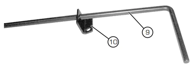
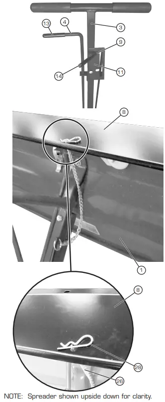
- Slide Spread Plate Shutoff Lever (9) into Shutoff Guide (10) as shown.

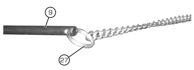
- Assemble Key Ring (27) assembly to end of the Spread Plate Shutoff Lever (9).

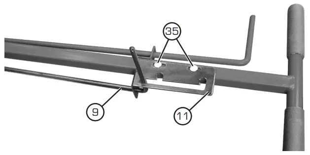
- Insert Spread Plate Shutoff Lever (9) into Lever Lock (11) as shown, then install Lever Lock (11) as shown using two 1/4″-20 x 1-1/2″ Carriage Bolt (35) and two 1/4″-20 Flange Nuts (34, Not Shown).

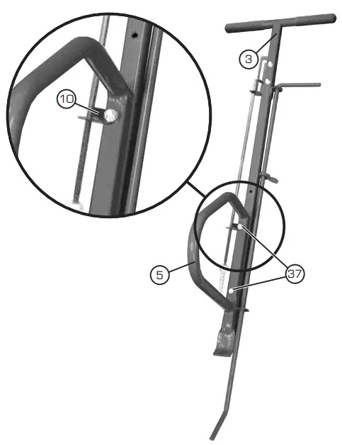
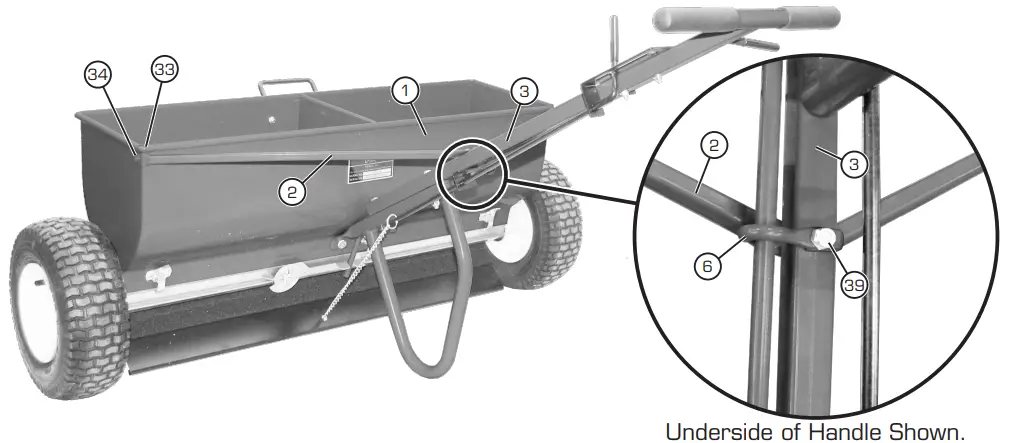
- Assemble Handle (3) to Parking Leg (5) using two 5/16″-18 x 2-1/2″ Hex Bolts (36, Not Shown) and two 5/16″-18 Nylon Lock Nuts (37). Be sure to install Shutoff Guide (10) as shown.

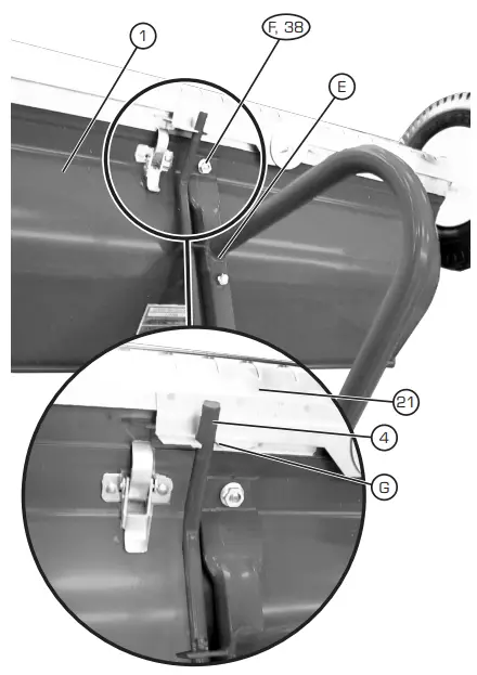
- Install Handle Assembly (E) to Hopper Body (1) as shown. Install onto Stud (F) and attach with 5/16″- 18 Flange Nut (38).
NOTE: Rate Adjustment Lever (4) must sit in Notch (G) when using Variable Rate Bottom (21) as shown.
- Attach Shutoff Lever Guide (6) and Handle Brace (2) to Handle (3) using 1/4″-20 x 1-3/4″ Hex Bolt (40, Not Shown) and 1/4″-20 Lock Nut (39). Attach Handle Brace (2) to Hopper Body (1) as shown using one 1/4″-20 x 1/2″ Hex Bolts (33) and one 1/4″-20 Flange Nuts (34) for each end.

For Users of the Fixed Rate Bottom
NOTE: When using the Fixed Rate Bottom (29), The Spread Plate (8) rubber pad should contact the Fixed Rate Bottom as specified in Step 7. - Adjustment of the Spread Plate Shutoff Lever (9):
With Spread Plate Shutoff Lever (9) in highest position in the Lever Lock (11), fully lift Spread Plate (8) and install Hair Pin Cotter (28) through #50 Sash Chain (26) to hold the Spread Plate (8) tight against the bottom of the Hopper Body (1). You may need to adjust the Spread Lever Lock (11) on Handle (3) to get a better fit. You may need to install the cotter pin several links up on the chain for proper fit.
For Users of the Variable Rate Bottom
NOTE: When using the Variable Rate Bottom (21), the Spreader Plate (8) rubber pad should face away from the Variable Rate Bottom (21) as specified in Step 7.
Angle of the Spread Plate (8) can be controlled by making adjustments to the position of the Spread Plate Lever (9), Lever Lock (18), Hair Pin Cotter (28) and the #50 Sash Chain (26). Set the Spread Plate (8) so that it is 1/2″ off the ground when the drop spreader rests on a flat surface. When you are traveling over terrain, the Spread Plate (8) should just touch the ground. Use the Rate Adjustment Lever (4) to open and close the Variable Rate Bottom. - Install Shutoff Grip (13) onto Rate Adjustment Lever (4), and install Lever Grip (14) onto Spread Plate Shutoff Lever (9).

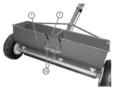
- Install Lift Handle (7) to Hopper Body (1) using two 1/4″-20 x 1/2″ Hex Bolts (33) and two 1/4″-20 Flange Nuts (34, Not Shown).

MAINTENANCE
Empty When Finished, Remove Hopper Bottom and Rotors
- After hopper has been emptied, turn hopper over, straighten and remove 7/64″ Cotter Pins (44), pull 0.172″ x 1.60″ Clevis Pins (43) out of Pneumatic Wheels (24), and remove Pneumatic Wheels.
- Loosen and remove 5/16″ Wingnuts (31) securing End Bearing Retainers (15,16). Remove the End Bearing Retainers (15, 16) and the Spread Plate (8).
- Loosen the latches that secure bottom (21 or 29), and remove bottom. Remove End Bearings (17), Rotor End Washers (19), and Rotor Bars (20).
- Wipe all parts clean.
- Place a few drops of oil on the end and center bearings after each use. The bearings are oil impregnated and will replenish themselves to their absorption capacity. Some materials have a fine powder in the mixture, so it may be necessary to oil the bearings more often to prevent the powder from working into them.
- Reassemble. IF NECESSARY, REMOVE SLIDE FROM HOPPER BOTTOM FOR CLEANING
- If some materials build up on the hopper bottom, especially when humidity is high, disassemble the slide assembly by removing the #10 Nylon Locknuts (42), #10 Nylon Washers (41) and slide hanger. Wipe clean.
- Reassemble slide on hopper bottom. For proper slide tension when reassembling slide, gently drive the hanger to the left until the dimple in the slide hanger and bottom match. Secure slide hanger with #10 Nylon Washers (41) and #10 Nylon Locknuts (42).
TO CHANGE HOPPER BOTTOM TYPE:
- Place spreader upside down.
- Remove the Hair Pin Cotter (28) that holds the #50 Sash Chain (26) to the Spread Plate (8). Tilt the Spread Plate (8) away from the Hopper Body (1).
- Unlatch each of the six latches that hold the current bottom in place and lift the bottom piece out of the hopper.
- Align and press the desired bottom piece into the grooves on the hopper body as specified in the assembly Step 4.
NOTE: Ensure that Rate Adjustment Lever (4) is aligned into notch during reassembly while installing the Variable Rate Bottom.
NOTE: Ensure that Spread Plate (8) is oriented correctly as shown in assembly Step 7. - Reattach the Hair Pin Cotter (28) onto the #50 Sash Chain (26) to control the shut off or angle of the Spread Plate (8) as specified in assembly Step 18.
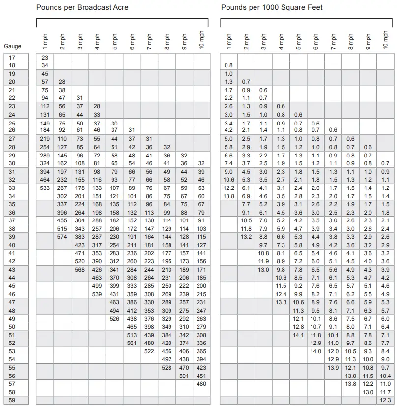
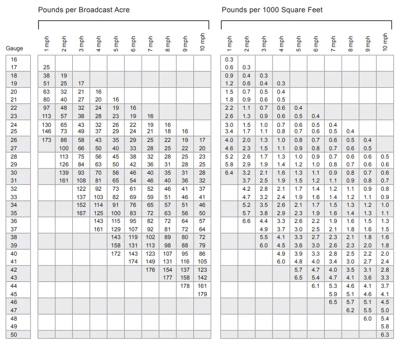
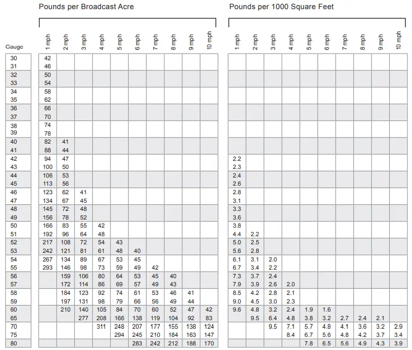
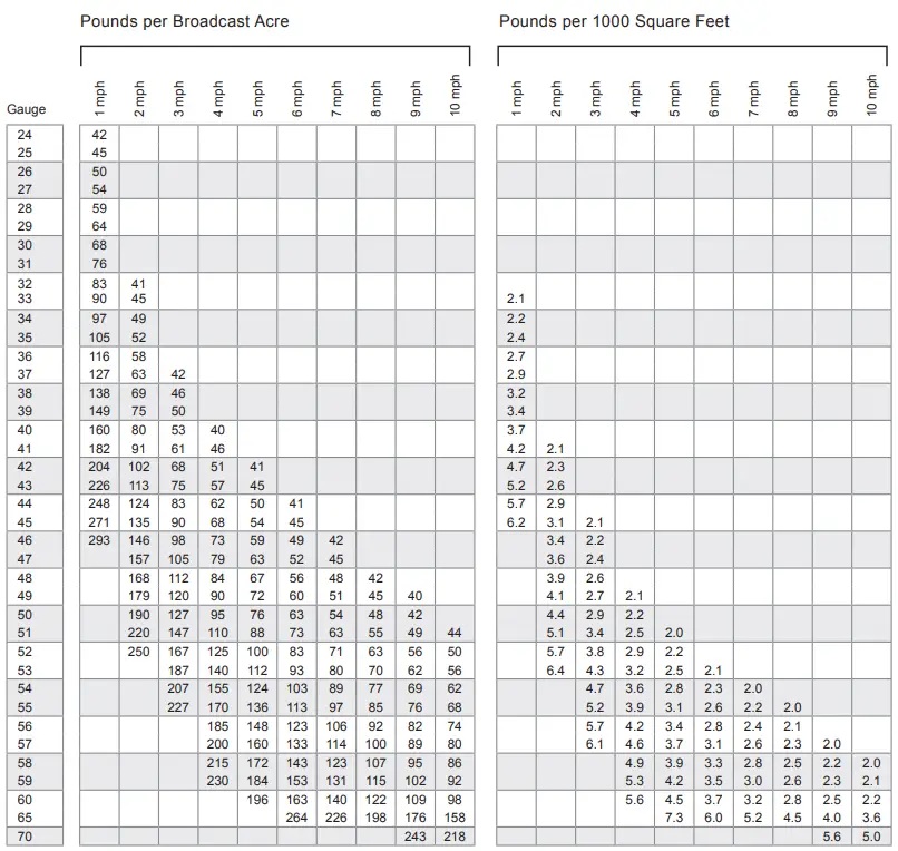
CALIBRATION APPLICATION
DETERMINE APPLICATION SPEED
Use these distance traveled in one minute:
| 1 mph 88 ft | 2 mph 176 ft | 3 mph 264 ft | 4 mph 352 ft | 5 mph 440 ft |
| 1 km/h 16.67 m | 2 km/h 33.34 m | 3 km/h 50 m | 4 km/h 66.68 m | 5 km/h 83.35 m |
SET GAUGE
Move gauge away from the stop before attempting adjustment. Turn gauge to desired number, using the top surface of the stop as the setting indicator.
You can ‘fine tune’ the gauge with extreme precision. The gauge is marked in increments of one. If you adjust one tenth of one gauge stop, from 27.7 to 27.8, for example, the slide will open approximately on thousandth of an inch more.
Check your results as outlined in Step 3 and make adjustments as necessary.
NOTE: Always move the gauge away from the stop before attempting to set the gauge.
CHECK RATE
Making a precision application is now simply a matter of filling up the hopper, moving the lever so the gauge is against the stop, walking at your selected speed, and checking your rate.
Check your rate as follows:
- Empty the hopper of all material.
- Dump two 50 lb bags (or whatever size is standard for the material you are using) into the hopper-placing one bag into each “half” of the hopper.
- Treat a known area, such as 1,000 square feet at your desired speed.
- Empty and weigh the material that is left inside the hopper after treatment.
- Calculate the rate in lbs/sq.ft by using:
(Weight (Weight
Before After
Treatment) – Treatment)
Rate = Area Treated
NOTE: Weights are measured in lbs, and Area Treated is measured in sq.ft.
NOTE: When first using the spreader and checking rate, it is best to start with a lower (smaller gate opening) gauge number.
Applying product at a higher rate than product specification could damage turf.
It is important that you check your rate to see that the setting you chose is giving you the results you want.
Atmospheric conditions alone can affect the flow of materials.
CAUTION: When applying high potency fertilizer that will burn, be sure to be moving when beginning application.
SPECIFICATIONS
| Model | P70-12010 36″ Drop Spreader |
| Hopper Capacity | 120 lbs. (1.8 cu.ft.) |
| Rotor | Three rods spaced uniformly around rotor. |
| Rotor Bearing | Porous, oil-impregnated, sintered bronze alloy, sleeve type. |
| Rate Gauge | Precision cam gauge |
| Adjustable Rate Bottom and Rate Control Slide | Stainless steel bottom and slide microprecision mated. Openings uniform for all gauge settings. Snaps off for cleaning. |
| Fixed Rate Bottom | Powder coated bottom with 1/2″ openings for a fixed flowrate. |
| Shut-Off | Crank lever closes slide of standard variable rate bottom. |
| Wheel | Rubber-tired 13″ molded plastic tire, 5″ wide. |
| Spread Plate | Standard, angle adjusted by chain to produce sheet-like application and actas wind guard. |
| Extra Equipment | Fixed-rate bottom to replace variablerate bottom. Applies top dressing or other material through fixed slot |
| Shipping Weight | 61 lbs. |
Herbicide / Fertilizer
For Spreader P70-12010
22-5-7 | Weed and Feed Herbicide / Fertilizer

24-3-6 | Fertilizer with 1.5% Team
Chemical
For Spreader P70-12010
Diazinon 5G

Oftanol 1.5%
Seed
For Spreader P70-12010
Classic Grass Seed
Eagle Blend Grass
WARRANTY
1 YEAR LIMITED WARRANTY
This is warranted to the original purchaser only. Spyker will replace parts with defects in materials and workmanship, for a period of one year from the date of purchase.
For Spyker Spreaders–a Brinly-Hardy Company, products employing metal gear systems, pinion and bevel, these metal gears, only, not inclusive of any other parts or materials, are warranted for the life of the spreader, not to be used for replacement or repair past original purchase.
Spyker Spreaders will not be liable for any loss, damage or expense including, but not limited to, consequential or incidental damages, arising from the operation, condition or use of the item. The sole and exclusive remedy against Spyker Spreaders being the replacement of the defective parts. This warranty gives you specific legal rights, and you may also have other rights which vary from state to state.
This express warranty, which is applicable only to the original purchase, is in lieu of and excludes all other warranties, whether expressed or implied by operation of law or otherwise, including any warranty of merchantability or fitness for particular purpose.
SPYKER SPREADERS
Jeffersonville, IN 47130 USA
Phone: 800.972.6130


