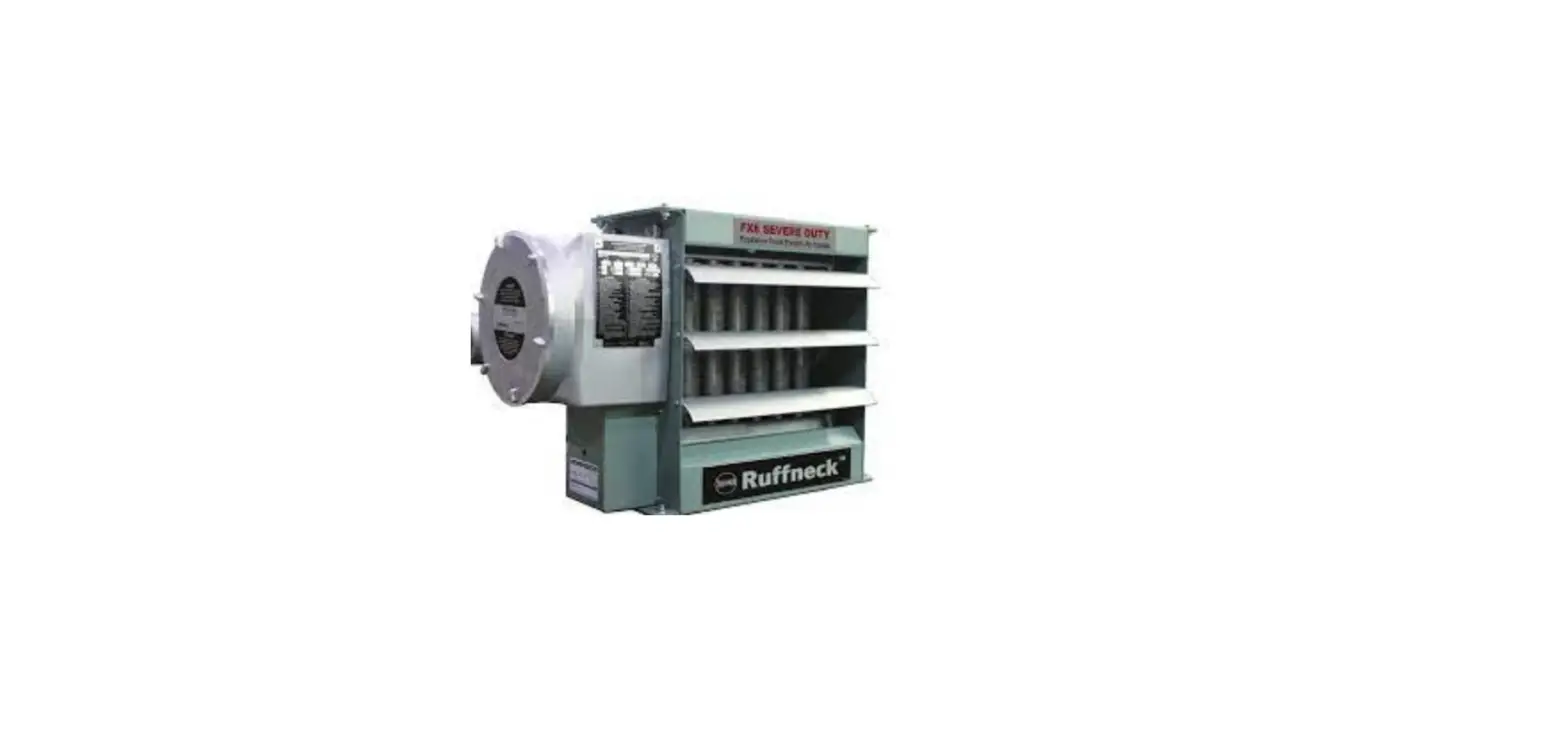
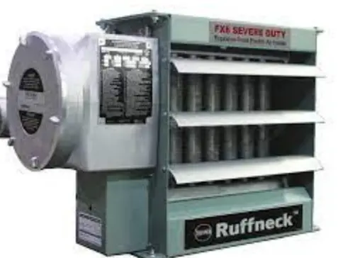
 Ruffneck FX6-SD Series Explosion Proof Electric Air Heaters
Product Information
The FX6SD Series ExplosionProof Electric Air Heaters are the next generation RuffneckTM explosion-proof electric air heaters, designed for severe duty applications that can lead to accelerated wear of electrical components and damage to the heater core. The FX6-SD is specifically designed for harsh environments including locations with fluctuating power quality, temporary power generation, high vibration, dirty or corrosive atmospheres, or extended maintenance intervals. The FX6-SD incorporates a dedicated shunt trip circuit breaker which operates independently of the control circuit. It is triggered by a redundant heater core high-temperature limit enabling primary interruption of line power to safely protect the heater core. Additional standard features include a definite-purpose high-capacity contactor, explosion-proof Arctic Duty motor, and heavy gauge wiring to make the FX6-SD the safest and most robust explosion-proof unit heater available. FX6-SD heaters are CULUS approved for use in hazardous locations. The heaters come with NEMA type 7 & 9 enclosures, 75 amp industrial contactor with the severe-duty coil, industrial duty line circuit breaker with shunt trip and manual reset, built-in control transformer, terminals for optional thermostat connection, automatic reset bimetal high-limit, shunt trip high limit, copper bus bars, built-in fuse protects contactor coil, spare fuse located in the convenient holder, Arctic Duty Motor, liquid-filled lower tank, printed circuit board, 100 psig (690 kPa) pressure relief valve, primary pressure relief valve, and standard secondary pressure relief device.
Product Usage
- Before using the FX6SD Series ExplosionProof Electric Air Heaters, ensure that you have read and understood the user manual and safety instructions.
- Verify that the voltage and phase of the heater match your power supply.
- Install the heater in a suitable location as per the installation conditions mentioned in the user manual.
- Connect the heater to the power supply and ensure that all electrical connections are tight and secure.
- If using an optional thermostat, connect it to the terminals provided in the heater.
- Turn on the power supply and set the thermostat to the desired temperature, if applicable.
- The heater will start heating the air and maintain the desired temperature until turned off or until the thermostat reaches the set temperature.
- In case of any abnormality or malfunction, turn off the power supply and refer to the troubleshooting section in the user manual.
- Regularly inspect and maintain the heater as per the maintenance instructions provided in the user manual to ensure safe and efficient operation.
The FX6-SD is the next generation Ruffneck™ explosion-proof electric air heater, built for severe duty applications that can lead to accelerated wear of electrical components and damage to the heater core. The FX6-SD is specifically designed for severe duty applications including locations with:
- Fluctuating power quality
- Temporary power generation
- High vibration
- Dirty or corrosive atmospheres or
- Extended maintenance intervals
Only the Ruffneck™ FX6-SD incorporates a dedicated shunt trip circuit breaker which operates independent of the control circuit.It is triggered by a redundant heater core high-temperature limit enabling primary interruption of line power to safely protect the heater core. Additional standard features include a definite purpose high capacity contactor, explosion-proof Arctic Duty motor and heavy gauge wiring to make the FX6-SD the safest and most robust explosion-proof unit heater available. FX6-SD heaters are CULUS approved for use in hazardous locations.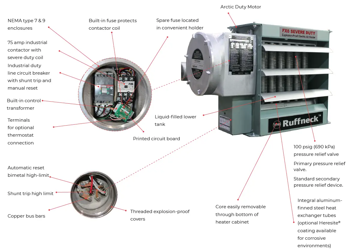
Table 5 – Performance Data for 60 Hertz FX6-SD cULus Temperature Code T3B 329°F (165°C)
| Nominal Wattage | Model | Voltage | Phase | Total Current | Optional Built-in Disconnect Switch | Air Temperature Rise | Btu/hr | |
| kW | °F | °C | ||||||
| A | ||||||||
|
3 | FX6-SD-208160-030 | 208 | 1 | 14.4 |
DS |
19.0 |
10.5 |
10,250 |
| FX6-SD-208360-030 | 208 | 3 | 8.3 | |||||
| FX6-SD-240160-030 | 240 | 1 | 12.5 | |||||
| FX6-SD-240360-030 | 240 | 3 | 7.2 | |||||
| FX6-SD-480160-030º | 480 | 1 | 6.3 | |||||
| FX6-SD-480360-030 | 480 | 3 | 3.6 | |||||
| FX6-SD-600360-030 | 600 | 3 | 2.9 | |||||
|
5 | FX6-SD-208160-050 | 208 | 1 | 24 |
DS |
31.6 |
17.6 |
17,050 |
| FX6-SD-208360-050 | 208 | 3 | 13.9 | |||||
| FX6-SD-240160-050 | 240 | 1 | 20.8 | |||||
| FX6-SD-240360-050 | 240 | 3 | 12 | |||||
| FX6-SD-480160-050º | 480 | 1 | 10.4 | |||||
| FX6-SD-480360-050 | 480 | 3 | 6 | |||||
| FX6-SD-600360-050 | 600 | 3 | 4.8 | |||||
|
7.5 | FX6-SD-208160-075 | 208 | 1 | 36.1 |
DS |
27.9 |
15.5 |
25,600 |
| FX6-SD-208360-075 | 208 | 3 | 20.8 | |||||
| FX6-SD-240160-075 | 240 | 1 | 31.3 | |||||
| FX6-SD-240360-075 | 240 | 3 | 18 | |||||
| FX6-SD-480160-075º | 480 | 1 | 15.6 | |||||
| FX6-SD-480360-075 | 480 | 3 | 9 | |||||
| FX6-SD-600360-075 | 600 | 3 | 7.2 | |||||
|
10 | FX6-SD-208160-100* | 208 | 1 | 48.1 | Not Available |
37.2 |
20.6 |
34,100 |
| FX6-SD-208360-100 | 208 | 3 | 27.8 |
DS | ||||
| FX6-SD-240160-100 | 240 | 1 | 41.7 | |||||
| FX6-SD-240360-100 | 240 | 3 | 24.1 | |||||
| FX6-SD-480160-100º | 480 | 1 | 20.8 | |||||
| FX6-SD-480360-100 | 480 | 3 | 12 | |||||
| FX6-SD-600360-100 | 600 | 3 | 9.6 | |||||
|
15 | FX6-SD-208360-150 | 208 | 3 | 41.6 | Not Available |
27.1 |
15.1 |
51,200 |
| FX6-SD-240160-150* | 240 | 1 | 62.5 |
DS | ||||
| FX6-SD-240360-150 | 240 | 3 | 36.1 | |||||
| FX6-SD-480160-150º | 480 | 1 | 31.3 | |||||
| FX6-SD-480360-150 | 480 | 3 | 18 | |||||
| FX6-SD-600360-150 | 600 | 3 | 14.4 | |||||
| 20 | FX6-SD-480160-200º | 480 | 1 | 41.7 | DS | 36.1 | 20.1 | 68,250 |
| FX6-SD-480360-200 | 480 | 3 | 24.1 | |||||
| FX6-SD-600360-200 | 600 | 3 | 19.2 | |||||
| 25 | FX6-SD-480360-250 | 480 | 3 | 30.1 | DS | 22.0 | 12.2 | 85,300 |
| FX6-SD-600360-250 | 600 | 3 | 24.1 | |||||
| 30 | FX6-SD-480360-300 | 480 | 3 | 36.1 | DS | 26.4 | 14.6 | 102,350 |
| FX6-SD-600360-300 | 600 | 3 | 28.9 | |||||
| 35 | FX6-SD-480360-350 | 480 | 3 | 42.1 | DS5 | 30.7 | 17.1 | 119,450 |
| FX6-SD-600360-350 | 600 | 3 | 33.7 | |||||
See Model Coding, page 16 and Installation Conditions, page 14. Consult Terms & Conditions of Sale or FX6 Owner’s Manual for warranty information.
Note: Exceeds the 48 amp circuit limit of NEC 424-22 º 480 V 1 Phase units are certified Class I, Div. 1, Group D and Class II, Div. 1, Groups F and G.
- Minimum conductor size for 86°F (30°C) ambient. Derate conductor for ambient temperature. Use minimum 90°C (194°F) insulation.
- Heater is functioning normally if at rated voltage the amp draw is within 10% of the value in this table.
- Operation at lower voltage will result in reduced heat output and amp draw.
- Add ”T” to model number when adding a built-in thermostat.
- Add ”D” to model number when adding a built-in disconnect switch.
- Add ”C” to model number for units with Heresite® coating.
- Add ”A” to model number for units with stainless-steel cabinet.
- Add “U” to model number for continuous fan.
Table 6 – Performance Data for 50 Hz FX6-SD – Class I, Division 1 & 2, Groups C & D; Class II, Division 1, Groups E, F & G; Class II, Division 2, Groups F & G; Class I, Zones 1 & 2, Groups IIA & IIB. Temperature Code T3B 329°F (165°F)
| Nominal Wattage (kW) | Optional Built-in Disconnect Switch | Air Temperature Rise | ||||||
| Model | Voltage | Phase | Total Current (A) | Btu/hr | ||||
| °F | °C | |||||||
| 2.5 | FX6-SD-220150-025 |
220 |
1 | 11.4 |
DS | 19.7 | 11.0 | 8,550 |
| 4.2 | FX6-SD-220150-042 | 19.1 | 33.2 | 18.4 | 14,350 | |||
| 6.3 | FX6-SD-220150-063 | 28.6 | 28.5 | 15.7 | 21,500 | |||
| 8.4 | FX6-SD-220150-084 | 38.2 | 37.8 | 21.1 | 28,700 | |||
| 12.6 | FX6-SD-220150-126* | 57.3 | Not Available | 27.5 | 15.2 | 43,000 | ||
| 2.8 | FX6-SD-230150-028 |
230 |
1 | 12.20 |
DS | 22.1 | 12.3 | 9,550 |
| 4.6 | FX6-SD-230150-046 | 20.0 | 36.4 | 20.2 | 16,000 | |||
| 6.9 | FX6-SD-230150-069 | 30.0 | 31.1 | 17.2 | 23,550 | |||
| 13.8 | FX6-SD-230150-138* | 59.9 | Not Available | 30.1 | 16.6 | 47,100 | ||
| 2.5 | FX6-SD-380350-025 |
380 |
3 | 3.8 |
DS | 19.7 | 11.0 | 8,550 |
| 4.2 | FX6-SD-380350-042 | 6.4 | 33.2 | 18.4 | 14,350 | |||
| 6.3 | FX6-SD-380350-063 | 9.6 | 28.5 | 15.7 | 21,500 | |||
| 8.4 | FX6-SD-380350-084 | 12.8 | 37.8 | 21.1 | 28,700 | |||
| 12.5 | FX6-SD-380350-125 | 19.0 | 27.2 | 15.1 | 42,700 | |||
| 20.9 | FX6-SD-380350-209 | 31.8 | 22.0 | 12.1 | 71,350 | |||
| 2.8 | FX6-SD-400350-028 |
400 |
3 | 4.0 |
DS | 22.1 | 12.3 | 9,550 |
| 4.6 | FX6-SD-400350-046 | 6.6 | 36.4 | 20.2 | 15,700 | |||
| 6.9 | FX6-SD-400350-069 | 10.0 | 31.1 | 17.2 | 23,550 | |||
| 9.3 | FX6-SD-400350-093 | 13.4 | 42.0 | 23.2 | 31,750 | |||
| 13.9 | FX6-SD-400350-139 | 20.1 | 30.2 | 16.7 | 74,450 | |||
| 18.5 | FX6-SD-400350-185 | 26.7 | 40.2 | 22.3 | 63,150 | |||
| 23.1 | FX6-SD-400350-231 | 33.3 | 24.2 | 13.5 | 78,850 | |||
| 3.7 | FX6-SD-415350-037 |
415 |
3 | 5.1 |
DS | 29.3 | 16.3 | 12,650 |
| 7.5 | FX6-SD-415350-075 | 10.4 | 33.8 | 18.7 | 25,600 | |||
| 14.9 | FX6-SD-415350-149 | 20.7 | 32.5 | 18.1 | 50,850 | |||
| 22.4 | FX6-SD-415350-224 | 31.2 | 23.5 | 13.1 | 76,450 | |||
| 4.2 | FX6-SD-440350-042 |
440 |
3 | 5.5 |
DS | 33.2 | 18.4 | 14,350 |
| 8.4 | FX6-SD-440350-084 | 11.0 | 37.8 | 21.1 | 28,700 | |||
| 16.8 | FX6-SD-440350-168 | 27.5 | 36.5 | 20.3 | 57,350 | |||
| 20.9 | FX6-SD-440350-209 | 27.5 | 22.1 | 12.2 | 71,350 | |||
Note:
Exceeds the 48 amp. circuit limit of NEC 424-22.
- Minimum conductor size for 86°F (30°C) ambient. Derate conductor for ambient temperature use minimum 194°F (90°C) insulation.
- Heater is functioning normally if at rated voltage the amp draw is within 10% of the value in this table.
- Operation at lower voltage will result in reduced heat output and amp draw.
Installation Conditions- The FX6-SD Series Electric Air Heaters are for dry indoor use only. Do not immerse in water. Do not store or use in areas exposed to rain or snow.
- The FX6-SD heaters are to be used only in atmospheres having an ignition temperature higher than 329°F (165°C).
- Altitude restrictions apply – see specifications on next page.
- Add ”T” to the model number when adding a built-in thermostat.
- Add ”D” to the model number when adding a built-in disconnect switch.
- Add ”C” to the model number for units with Heresite® coating.
- Add ”A” to the model number for units with stainless-steel cabinets.
- Add “U” to the model number for continuous fan.
- Heaters should be connected to a fixed power supply and must be permanently mounted in a level, upright position during operation.
- Read and be aware of the terms of our Warranty located in the owner’s manual.
- For more information please refer to the owner’s manual.
Table 7 – Specifications for 50 Hz FX6-SD
| Nominal kW | |||||||||||
| 2.5 | 3.7 & 4.6 | 6.3 & 7.5 | 8.4 | 12.5 & 12.6 | 14.9 & 16.7 | 20.9 | 22.4 | 35 | |||
| Maximum Altitude | ft | 12,000 | 8,000 | 10,000 | 7,000 | 10,000 | 7,000 | 10,000 | 7,000 | 6,000 | |
| m | 3,658 | 2,438 | 3,048 | 2,134 | 3,048 | 2,134 | 3,048 | 2,134 | 1,829 | ||
| Air Flow | @ 70°F (CFM) | 400 | 700 | 1,450 | 3,000 | ||||||
| @ 21°C (m3/hr) | 679 | 1,189 | 2,463 | 5,096 | |||||||
| Horizontal Air Throw | ft | 13 | 25 | 35 | 60 | ||||||
| m | 4.0 | 7.6 | 10.7 | 18.2 | |||||||
| Maximum Mounting Height (to underside) | ft | 7 | 10 | 20 | |||||||
| m | 2.1 | 3.0 | 6.1 | ||||||||
| Minimum
Motor Power | HP | 1/2 | |||||||||
| kW | 0.373 | ||||||||||
| Fan Diameter | in | 12 | 16 | 20 | |||||||
| mm | 305 | 406 | 508 | ||||||||
|
Net Weight | without DS | lbs | 148 | 177 | 212 | ||||||
| kg | 67.1 | 80.2 | 96.2 | ||||||||
| with DS | lbs | 160 | 189 | 224 | |||||||
| kg | 72.5 | 95.6 | 101.6 | ||||||||
|
Shipping Weight | without DS | lbs | 202 | 227 | 263 | ||||||
| kg | 91.6 | 103.9 | 119.3 | ||||||||
| with DS | lbs | 214 | 239 | 275 | |||||||
| kg | 97 | 108.3 | 124.7 | ||||||||
Note: For specifications common to all FX6-SD models, see Model Coding, page 16. Weights are an approximate maximum. Manufacturer reserves the right to replace motors with suitable alternates.
Table 8 – Specifications for 60 Hz FX6-SD
|
| Nominal kW | ||||||||||
| 3 | 5 | 7.5 | 10 | 15 | 20 | 25 | 30 | 35 | |||
| Maximum Altitude | ft | 12,000 | 8,000 | 10,000 | 7,000 | 10,000 | 7,000 | 10,000 | 7,000 | 6,000 | |
| m | 3,658 | 2,438 | 3,048 | 2,134 | 3,048 | 2,134 | 3,048 | 2,134 | 1,829 | ||
| Air Flow | @ 70°F (CFM) | 500 | 850 | 1750 | 3600 | ||||||
| @ 21°C (m3/hr) | 850 | 1444 | 2973 | 6116 | |||||||
| Horizontal Air Throw | ft | 15 | 30 | 40 | 70 | ||||||
| m | 4.6 | 9.1 | 12.2 | 21.3 | |||||||
| Maximum Mounting Height (to underside) | ft | 7 | 10 | 20 | |||||||
| m | 2.1 | 3.0 | 6.1 | ||||||||
| Minimum
Motor Power | HP | 1/2 | |||||||||
| kW | 0.373 | ||||||||||
| Fan Diameter | in | 12 | 16 | 20 | |||||||
| mm | 305 | 406 | 508 | ||||||||
|
Net Weight | without DS | lbs | 148 | 177 | 212 | ||||||
| kg | 67.1 | 80.2 | 96.2 | ||||||||
| with DS | lbs | 160 | 189 | 224 | |||||||
| kg | 72.5 | 95.6 | 101.6 | ||||||||
|
Shipping Weight | without DS | lbs | 202 | 227 | 263 | ||||||
| kg | 91.6 | 103.9 | 119.3 | ||||||||
| with DS | lbs | 214 | 239 | 275 | |||||||
| kg | 97 | 108.3 | 124.7 | ||||||||
Note: For specifications common to all FX6-SD models, see Model Coding, page 16. Weights are an approximate maximum. The manufacturer reserves the right to replace motors with suitable alternates.
Model Coding
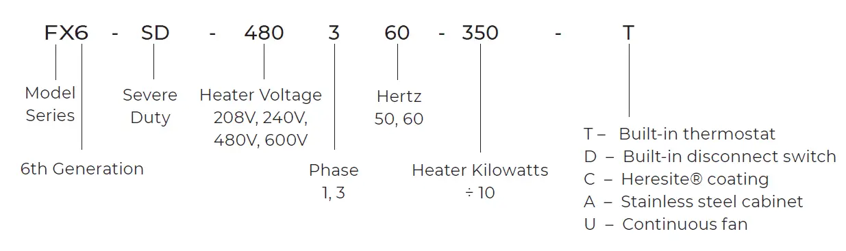
Reminder: This nomenclature illustration is intended primarily to explain how a product part number is defined. Not all voltage and/or wattage combinations are available – please consult the Performance Data chart(s) for product availability.
General Specifications
| 1. Hazardous Location Rating | Class I, Division 1 & 2, Groups C & D Class II, Division 1, Groups E, F & G Class II, Division 2, Groups F & G Class I, Zones 1 & 2, Group IIA & IIB Temperature Code T3B 329ºF (165ºC) |
| 2. Motor Type | Explosion-proof. Thermally protected TEFC Arctic Duty. Permanently lubricated ball bearings. |
| 3. Fan | Aluminum blade. Steel spider and hub with 5/8″ (15 mm) bore |
| 4. Fan Guard | Split design with close wire spacing. 1/4″ (6.3 mm) diameter probe will not enter |
| 5. Mounting Holes | Four 5/8″ (15.9 mm) diameter holes at the top of heater |
| 6. Heating Elements | Long-life metal-sheathed elements |
| 7. Temperature High- Limit | Primary automatic reset type, snap-action bimetal, open on temperature rise. Rated 100,000 cycles at 15 amp, handles 0.128 amps/Secondary automatic reset type, snap-action bimetal, close on temperature rise. Rated 100,000 cycles at 15 amp, handles 0.128 amps |
| 8. Control Circuit | 120 V, 0.128 amps, 15 VA. (Grounded) |
| 9. Optional Built-in Thermostat | Explosion-proof 36ºF to 82ºF (2°C to 28°C) |
| 10. Optional Built-in Thermostat | DS uses x-Max® construction. |
| 11. Contactor | Multiple voltage primary, 120 V secondary, 50 VA |
| 12. Heat Transfer Fluid | Proprietary heat transfer fluid. |
| 13. Cabinet Material | 12-gauge (0.315″ / 2.60 mm) epoxy powder coated steel. Optional Heresite® coating available for corrosive atmospheres with an optional stainless-steel casing |
| 14. Core | Steel with integral aluminum fins, vacuum charged and hermetically sealed |
| 15. Conduit Material | Heavy wall, 0.122″ (3.1 mm), steel |
| 16. Junction Box | 10.25″ (230 mm) x 8.00″ (180 mm) x 9.12″ (205 mm) |
| 17. Circuit Protection | Industrial duty line circuit breaker with shunt trip |
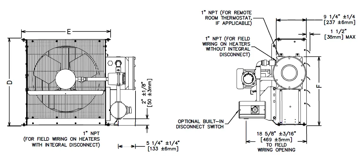
| 18. Field Connection | Two 1″ NPT |
| 19. Overpressure Protection | Preset 100 psig (690 kPa) pressure relief valve, no field serviceable parts. Preset 300 PSIG (2070 KPa) rupture disk, no field servicable parts. |
| 20.Operational Temperature Limitations | -58°F to 104°F (-50°C to 40°C) |
| 21. Storage Limitations | -58°F to 176°F (-50°C to 80°C). Do not immerse in water. Do not expose to rain or snow. |
| 22. Weight (for 15 kW Unit) | 170 lbs (77.27 kg) |
| 23.Weight with Disconnect (for 15 kW Unit) | 182 lbs (82.73 kg) W |


