Cig Shanghai M97RG2 MoCa2.5 Wi-Fi Extender
Preface
About This Document
This guide describes how to install the CIG Wi-Fi extender device unit ( Gateway ) at the customer premises.
Intended Audience
This document is intended for technicians responsible for:
- Unpacking and mounting the Gateway and power supply
- Connecting the Gateway to the MoCa2.5 network
- Auto-negotiation and MDI/MDIX auto-sensing
- Built-in layer-2 switch
- Advanced data features such as VLAN tag manipulation, classification, and filtering
- The M-97RG2 supports video service delivered in form of data (by multicast or unicast).
- M-97RG2 supports IGMP snooping function. When IGMP snooping is enabled, M-97RG2 monitors the member joining and leaving activities at the Ethernet/WLAN service port, and then selectively delivers the multicast streams.
Safety
Please read and follow all warning notices and instructions marked on the product or included in its packaging, and observe all safety instructions listed in this manual.
Basic Requirements
- Install the device in a well-ventilated place that is not directly exposed to sunlight.
- Keep the device dry and prevent the device from coming into contact with other objects during storage, transportation, and operation of the device.
- Install the device in compliance with the requirements.
- Do not open the device enclosures without permission, but contact the service technician when a problem occurs with the device.
- No entity or person should modify the structure, security design, performance design, etc. of the device without authorization.
- Abide by local laws and regulations and respect the legal rights of others when using the device.
Environmental Requirements
- Install the device in a well-ventilated place that is not directly exposed to sunlight.
- Keep the device clean.
- Keep the device away from water sources or wet places.
- Do not place any objects on top of the device. This is to protect the device from damage, such as overheating or melting, which can be caused by those objects.
- Leave a space of at least 50mm around the device for heat dissipation.
- Leave a space of at least 100mm on the top of the device for heat dissipation.
- Keep the device away from heat sources or fire sources, such as electric heaters and candles.
- Keep the device away from electrical appliances with strong magnetic fields or strong electric fields, such as microwave ovens, refrigerators, and mobile phones.
- Do not store the device in an environment where there are corrosive chemicals.
Electrical Safety
- Use the accessories delivered with the device, such as the power adapter, battery, etc..
- The power supply voltage and current of the device must meet the requirements on the input voltage and current of the device, and provide current overload protection.
- Keep the power plug clean and dry to avoid electric shock or other hazards.
- Follow the insulation requirements of operational safety, for example, keep your hands dry, use insulated tools, etc., when plugging in the device’s cables.
- Switch off the power and remove the power plug if the device needs to be shut down for a long period of time.
- Protect the device from water or other liquids. If such an incident occurs, switch off the power immediately and remove all the cables from the device, including the power cable, and network cables. Contact the service technician in the event of a device failure.
- Do not step on, pull, drag, or excessively bend the cables because they may become damaged. Damaged cables can cause a device failure.
- Do not use cables that are damaged or have deteriorated.
Instructions for Cleaning
- Before cleaning the device, stop the operation of the device, switch off the power, and remove all cables from the device, including the power cable, network cables, etc. When cleaning the device, do not use liquids such as cleaning fluid or spray-on detergents to clean the outer case of the device. Use a soft, dry cloth instead.
Other Instructions
- In case of any abnormalities, such as smoke, abnormal sound, or odor, being emitted from the device, immediately stop operation of the device, switch off the power, and remove all cables, from the device, including the power cable and network cables. Contact the service technician in the event of a device failure.
- Prevent foreign objects such as metal objects from falling into the device through the heat dissipation mesh.
- Protect the outer case of the device from scratches, as paint that peels off the scratched areas can cause device abnormalities. If the paint falls into the device it may cause short circuits. In addition, peeled-off paint can cause an allergic reaction in the human body.
- Ensure that the device is kept out of the reach of children. Guard against risks such as children playing with the device or swallowing small parts of the device.
Instructions for Environment Protection
- Deposit the used devices and batteries at the specified recycling facility.
- Abide by local laws and regulations when handling and disposing of packaging materials, dead batteries, and used devices
Product Description
Introduction
M-97RG2 is a high-performance Wi-Fi extender device with MOCA WAN and dual-band wireless interface, providing a cost-effective networking solution for both the home and office. The subscriber can utilize the existing coax cable network to extend their Wi-Fi coverage.
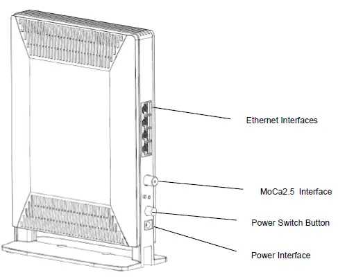
| Interface | Description |
| Power | 12 V DC power input interface, connecting to power adapter |
| RESET | Reset the Gateway |
| LAN1/LAN2/LAN3/LAN4 | RJ-45 10/100/1000 Base-T Ethernet Interface or 10/100 fast Ethernet Interface, connecting to PC or Set-Top-Box |
| MoCa2.5 | Connection established with MOCA client |
| ON/OFF | Power switch on/off the Gateway power |
Services
Data
- The M-97RG2 is delivered with four 10/100/1000 Base-T Ethernet and dual-band WLAN interfaces, supporting:
- Auto-negotiation and MDI/MDIX auto-sensing
- Built-in layer-2 switch
- Advanced data features such as VLAN tag manipulation, classification, and filtering
Video
The M-97RG2 supports video service delivered in form of data (by multicast or unicast).
M-97RG2 supports IGMP snooping function. When IGMP snooping is enabled, M-97RG2 monitors the member joining and leaving activities at the Ethernet/WLAN service port, and then selectively delivers the multicast streams.
Specifications
Gateway physical, electrical, MoCa2.5, and environmental specifications and compliance information are listed in the following tables.
Table 1 Physical specification
| Dimensions | 240mm(bracket inclusive) x170mm x72mm (H x W x D) |
| Weight | 1KG |
| MoCa2.5 interface | MOCA WAN frequency range:1125MHz~1675MHz TX Power: -1~+7dBm,typical +3dBm |
| Ethernet interface | RJ-45 connector |
Table 2 Electrical specification
| Input Power | +12V DC Power input |
| Power Supply | 2-PIN AC Power input |
| Power Consumption | <18W |
Table 3 Environmental specification
| Temperature | 0° C ~ 40° C |
| Humidity | 5% ~ 95% relative humidity |
Hardware Operation
Environmental Requirements
The Gateway will operate in temperatures ranging from 0° C to 40° C, with relative humidity ranging from 5% to 95%.
Power Requirements
The Gateway will be shipped with a universal power adaptor. However, before installation, check if the AC power input matches the specification printed on the power adaptor (input voltage, current, etc.)
CAUTION: Please use the power adaptor within the package only or the replacement unit provided by CIG. Other power adaptors may cause damage to the Gateway and other disasters.
Mountings the Gateway
The device supports two installation methods: Installed on the wall and installed on the desktop.
Installing the Gateway on the Wall:
- Locate a safe and accessible site for installation.
- Align the Gateway mounting bracket on the wall. There are two mounting directions, either horizontal or vertical. Make sure the install arrows is up when correctly mounted.
- Mount the bracket into a wall stud by driving the two sheet metal screws into the wall through the bracket mounting holes.
- Plugin the cables connector to connect the Gateway to the network.
Installing the Gateway on Desktop:
- Locate a safe and accessible site for installation.
- Place the Gateway unit on the desk.
- Plugin the cables connector to connect the Gateway to the network.
Uninstall the Gateway
For uninstalling the Gateway on the wall:
- Plug out the cables connector.
- If necessary, remove the screw on the brackets, and take off the brackets.
For uninstalling the Gateway on the desktop:
Plug out the cables connector.
Services enabled
Connecting Power
For AC power supply
- Plug the 2-pin 12V DC power connector of the AC power connector to the ONT AC power interface.
- Plug the input of the electricity cable into a live AC outlet.
- Verify that the power (PWR) LED on the Gateway is lit green indicating that local power is on and voltage is good.
Connecting Ethernet Interface
- Locate the premises’ Ethernet LAN cable.
- If the cable is not terminated, follow local practices to attach an RJ-45 connector. Table 8 shows Ethernet RJ-45 connector wiring information.
- Plug the Ethernet cable into the Gateway RJ-45 Ethernet port.
- Repeat steps 2-3 as needed to connect additional Ethernet cables.
Table 1 Ethernet RJ-45 connector wiring pattern
| Pin | Color | Signal | Pin | Color | Signal |
| 1 | Orange/White | Tx + | 5 | Blue/White | BI- |
| 2 | Orange | Tx- | 6 | Green | Rx — |
| Pin | Color | Signal | Pin | Color | Signal |
| 3 | Green/White | Rx + | 7 | Brown/White | BI- |
| 4 | Blue | BI- | 8 | Brown | BI- |
Verify the Installation and Services
Verify the Installation
Check LED states to verify Gateway status (Section 5.2). Services are not available until the Gateway is ranged and provisioned in the network. If services must be verified at the time of installation, refer to Section for additional instructions.
Activating the Gateway
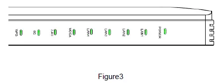
Once the Gateway installation is complete, follow the procedure below for verifying Gateway status. The figures below show the typical status LED display after the Gateway boot sequence is complete.
Gateway has not yet been provisioned:
MoCa2.5 has already been provisioned:
- Verify that the PWR LED lights are green indicating that local power level is good.
- Verify that the NET LED lights green, indicating that the Gateway interface is operating normally.
- The Gateway is placed into service remotely through the OLT. Services to the Gateway are likely wise provisioned and turned up remotely through the MoCa2.5 network.
- If the NET LED lights green, indicating that the Gateway is communicating with the MoCa2.5 network, no further action is necessary and you can proceed to Verifying Services.
Verifying Services
Follow local practices to connect to each active service port in the Gateway to confirm service activation.
- If Ethernet service is included in this installation, confirm that data is being received and transmitted normally. The LAN LED will be flashed during data transmission.
- If WLAN service is included in this installation, confirm that data is being received and transmitted on the WLAN interface. Verify the WLAN LED is green when the WLAN is connected.
Troubleshooting
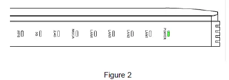
Gateway Status LEDs
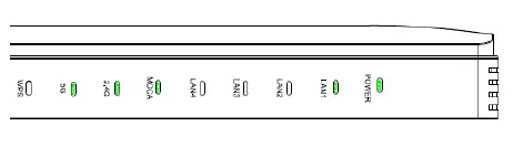
Figure4) Assist with installation and maintenance procedures. These LEDs are described in detail in Table4.
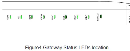
Table4 Gateway Status LEDs description
| NO | LED indicate | Status | Describe | |
| 1 | POWER | Green/Solid | Normal | |
| Off | No power | |||
| 2 | LAN1 | Green/Solid | Active or Link | |
| — | Green/Flash | data receive and transfer | ||
| Off | Not active | |||
| 3 | LAN2 | Green/Solid | Active or Link | |
| — | Green/Flash | data receive and transfer | ||
| Off | Not active | |||
| 4 | LAN3 | Green/Solid | Active or Link | |
| — | Green/Flash | data receive and transfer | ||
| Off | Not active | |||
| 5 | LAN4 | Green/Solid | Active or Link | |
| — | Green/Flash | data receive and transfer | ||
| Off | Not active | |||
|
6 |
MOCA | Green/Solid | Connection established with MOCA client with no traffic running | |
| — | Green/Flash/Slow | Establishing connection with MOCA client | ||
| — | Green/Flashing/Fast | Connection established with MOCA client and traffic is running | ||
| Off | No MOCA service provisioned | |||
| 7 | Green/Solid | WALN enable or Connected | ||
| — | Green/Flash | Data receive and transfer(2Hz flash) | ||
| Off | Error//WLAN disable | |||
| 8 | WLAN@5G | Green/Solid | WALN enable or Connected | |
| — | Green/Flash | Data receive and transfer(2Hz flash) | ||
| Off | Error//WLAN disable | |||
| 9 | WPS | Green/Solid | Linked | |
| — | Green/Flash | Button press and waiting for link | ||
| Off | Not active |
. Troubleshooting Procedures
| Problem | Possible Solutions |
|
The PWR LED is off | Check whether the ON/OFF button on the rear „ panel is pressed. |
| Check whether the power adapter matches the M-97RG2. | |
| Check whether the power connection is correct. | |
|
The LAN LED is off | Check whether the power connection is correct. |
| Check whether the Ethernet cable is connected correctly. | |
| Check whether the indicator of the network adapter is on. | |
| Check whether the network adapter works normally: Check whether there are devices with the? or! mark under Network adapters. If there are such devices, uninstall and then re-install them, or insert the network adapter into another slot. If the problem remains, change the network adapter. | |
| The Internet LED is off | Check if WAN port is configured correctly |
| The WPS LED is off | Check whether the WPS service is started. |
| The 2.5G LED is off | Check whether the WLAN service is started. |
| The 5G LED is off | Check whether the WLAN service is started. |
This device complies with part 15 of the FCC Rules. Operation is subject to the following two conditions:
- This device may not cause harmful interference
- This device must accept any interference received, including interference that may cause undesired operation.
This device complies with FCC radiation exposure limits set forth for an uncontrolled environment and it also complies with Part 15 of the FCC RF Rules. This equipment must be installed and operated in accordance with provided instructions and the antenna(s) used for this transmitter must be installed to provide a separation distance of at least 20 cm from all persons and must not be co-located or operating in conjunction with any other antenna or transmitter. End-users and installers must be provided with antenna installation instructions and consider removing the no-collocation statement.
Any changes or modifications not expressly approved by the party responsible for compliance could void the user’s authority to operate the equipment.
The equipment was tested and found to comply with EN 62368-1:2014/A11:2017; EN62311:2008. The equipment is tested and only used with a power adaptor included in the package.
The equipment complies with the requirements according to the following standard:
Email: [email protected]
- Product model name, part number, and serial number
- List of system hardware and software, including version
- Diagnostic error messages, if any
- Details about recent configuration changes, if applicable
Appendix C: Ordering
To order CIG components and documents, contact your local sales representative, or contact CIG at the address, telephone, fax number or e-mail address.
Address:
5/F, Building 8,
2388 ChenHang Road
MinHang District Shanghai 201114, China Phone: +86 21 8023 3300
Fax: +86 21 8023 3300
Email: [email protected]
Web URL: http://www.cambridgeig.com


 Installation Guide")


