STANLEY EP30200 Electronic Pin Brazing Unit User Manual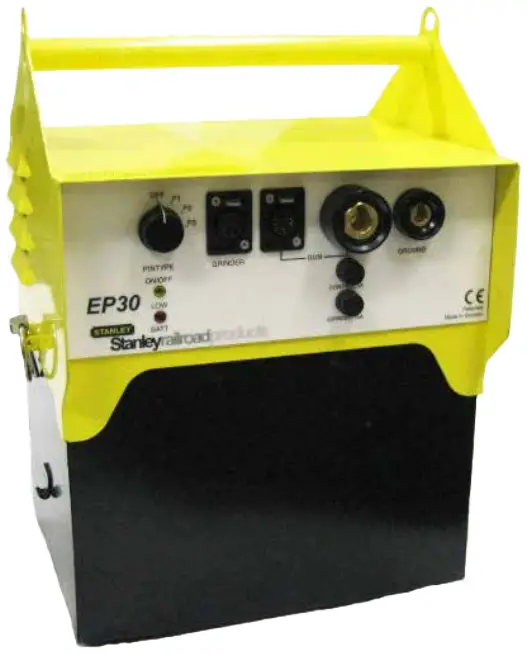
Important
To fill out a product warranty validation form, and for information on your warranty, visit www.stanleyinfrastructure.com and select the Company tab > Warranty.
Note: The warranty validation record must be submitted to validate the warranty
SERVICING: This manual contains safety, operation and routine maintenance instructions. STANLEY Infrastructure recommends that servicing of hydraulic tools, other than routine maintenance, must be performed by an authorized and certified dealer. Please read the following warning.
![]() Warning
Warning
SERIOUS INJURY OR DEATH COULD RESULT FROM THE IMPROPER REPAIR OR SERVICE OF THIS TOOL.
REPAIRS AND / OR SERVICE TO THIS TOOL MUST ONLY BE DONE BY AN AUTHORIZED AND CERTIFIED DEALER.
SAFETY SYMBOLS
![]() Safety symbols and signal words, as shown below, are used to emphasize all operator, maintenance and repair actions which, if not strictly followed, could result in a life-threatening situation, bodily injury or damage to equipment.
Safety symbols and signal words, as shown below, are used to emphasize all operator, maintenance and repair actions which, if not strictly followed, could result in a life-threatening situation, bodily injury or damage to equipment.
![]() Danger: This is the safety alert symbol. It is used to alert you to potential personal injury hazards. Obey all safety messages that follow this symbol to avoid possible injury or death.
Danger: This is the safety alert symbol. It is used to alert you to potential personal injury hazards. Obey all safety messages that follow this symbol to avoid possible injury or death.
![]() Warning :This safety alert and signal word indicates an imminently hazardous situation which, if not avoided, will result in death or serious injury.
Warning :This safety alert and signal word indicates an imminently hazardous situation which, if not avoided, will result in death or serious injury.
![]() Caution: This safety alert and signal word indicates a potentially hazardous situation which, if not avoided, could result in death or serious injury.
Caution: This safety alert and signal word indicates a potentially hazardous situation which, if not avoided, could result in death or serious injury.
Caution This safety alert and signal word indicates a potentially hazardous situation which, if not avoided, could result in death or serious injury.
Notice This signal word indicates a potentially hazardous situation which, if not avoided, may result in property damage.
Important This signal word indicates a situation which, if not avoided, will result in damage to the equipment.
Always observe safety symbols. They are included for your safety and for the protection of the tool.
LOCAL SAFETY REGULATIONS
Enter any local safety regulations here. Keep these instructions in an area accessible to the operator and maintenance personnel.
SAFETY PRECAUTIONS
- Tool operators and maintenance personnel must always comply with the safety precautions given in this manual and on the stickers and tags attached to the tool and hose.
- These safety precautions are given for your safety.
Review them carefully before operating the tool and before performing general maintenance or repairs. - Supervising personnel should develop additional precautions relating to the specific work area and local safety regulations. If so, place the added precautions in the space provided in this manual.
- This tool will provide safe and dependable service if operated in accordance with the instructions given in this manual. Read and understand this manual and any stickers and tags attached to the tool before operation. Failure to do so could result in personal injury or equipment damage.

- Operator must start in a work area without bystanders. The operator must be familiar with all prohibited work areas such as excessive slopes, dangerous terrain conditions and rail traffic.
- Establish a training program for all operators to ensure safe operation.
- Do not operate the tool unless thoroughly trained or under the supervision of an instructor.
- Always wear safety equipment such as goggles, ear, head protection and respiratory protection at all times when operating the tool.
- Do not inspect or clean the tool while the battery power source is connected. Accidental arcing can cause serious injury.
- Do not load brazing pins or ceramic rings while the battery power source is connected. Accidental arcing can cause serious injury.
- Do not use the tool while it is connected to a battery charger.
- Ensure battery charging is only done in a dry environment. Charging batteries in the rain or near standing water presents an electrocution hazard.
Read the safety and operation instructions provided with the battery charger before using the battery charger. - Do not operate a damaged, improperly adjusted or incompletely assembled tools.
- To avoid personal injury or equipment damage, all tool repair, maintenance and service must only be performed by authorized and properly trained personnel.
- Do not exceed the rated limits of the tool or use the tool for applications beyond its design capacity.
- Always keep critical tool markings, such as labels and warning stickers, legible.
- Always replace parts with replacement parts recommended by STANLEY.

EP30200 OPERATION
GENERAL PROTECTION
Store the Electronic Pin Brazing Unit in a place where it is protected from the elements, abrasive dust and damage.
Use only recommended replacement parts and materials specified in the Parts List section of this manual.
Use only recommended accessories specified in the Parts List section of this manual.
Do not use the Electronic Pin Brazers for applications it was not designed for.
Use the carrying handle to transport the unit.
CLEANING
Establish a routine to keep the unit as free from dirt as possible – daily, or at each shift change.
Pin Brazers exposed to rain, sand or grit-laden air should be cleaned prior to each use.
Keep tool labels and stickers legible.
PREPARATION PROCEDURES
Before putting a new Pin Brazer into initial service, or after an extended period of being unused, perform a visual inspection for bent, broken, cracked, missing or worn components.
INITIAL SETUP AND BATTERY CHARGING
![]() Warning
Warning
Failure to follow the instructions in the battery charger operation manual can result in battery explosion and serious bodily injury. To reduce the risk of battery explosion, read and understand the safety and operation instructions in the battery charger operation manual, the instructions published by the battery manufacturer and the instructions in this manual before attempting to charge the batteries.
![]() Warning
Warning
Make sure battery charging is only accomplished in a well ventilated room. DO NOT PLACE THE CONTROL BOX ON TOP OF THE BATTERIES. REMOVE THE BATTERY BOX COVER. Battery charging produces explosive gases. A battery explosion can cause serious injuries. Avoid battery explosions by keeping cigarettes, sparks and flames away from batteries during charging. Always wear safety glasses when working with batteries.
- The three batteries furnished are sealed, maintenance free batteries.
Sealed, maintenance free batteries do not contain cell caps and are already filled with battery acid. They will require charging before use.
Notice
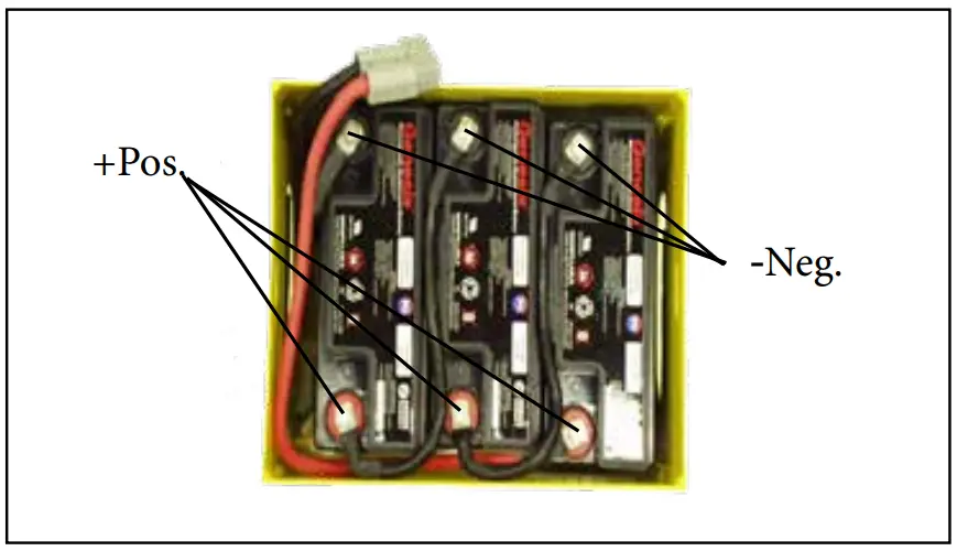
Use only battery charger specially made for pin brazing units (36V DC) approved by STANLEY. - Locate the four battery cables and connect them to the terminals on the batteries and the battery box as shown in Figure 1. Do not replace the lid on the battery box at this time.
Figure 1: Battery cable and terminals
- Insert the enclosed foam-rubber spacers between each battery and at both ends between the battery and the unit.
- Connect the battery charger to the grinder outlet on the unit, then to the mains. When removing the charger remove the main first, then remove the plug from the unit.
- Batteries will fully charge in approximately 3-5 hours.
Follow the instructions in the battery charger manual to complete the charging process. - Plug the two cable leads from the adapter box into the battery box.
- Insert the plug from the battery charger into the grinder outlet on the adapter box.
- Plug the battery charger into a standard 110 Volt AC outlet.
- Follow the instructions in the battery charger manual to complete the charging process.
CONNECTIONS
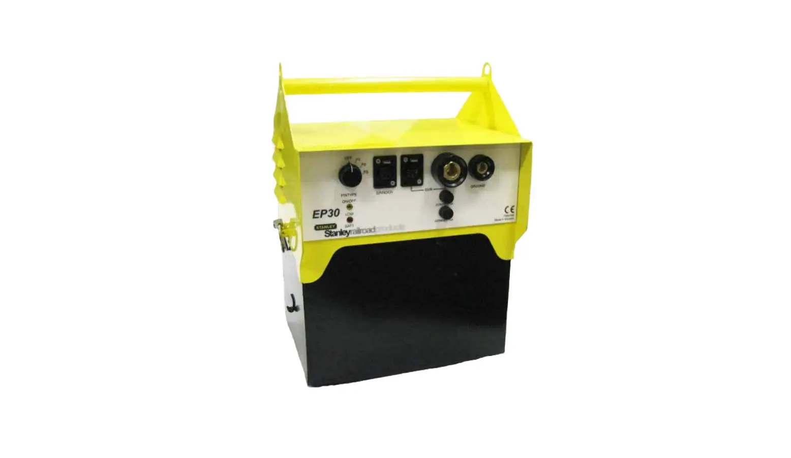
Figure 2: EP30 Connections
- Connect the brazing gun, power and trigger cables to the unit.
- Connect the ground cable.
- Connect the grinder
OPERATION
Prepare the rail surface
Select the type and length of bonding cable to use for the bond. Use it as a guide to determine where brazing points on the rail will be required.
![]() Caution
Caution
Always use eye protection when grinding and brazing.
- Grind the surface of the rail where brazing is going to be done, until the surface shows shiny metal, free of rust, corrosion, pits or other contamination. When grinding, use the edge of the grinding wheel – not the face of the wheel.
Note: Use only grinding wheels furnished by STANLEY. Other wheels have shown to leave residues which cause faulty brazing. - Grind the surface of the rail where the grounding cable will be placed to ensure a good ground. The grounding cable should be placed in close proximity to the brazing area.
PLACING THE GROUNDING CABLE
- When finished grinding the rail, place the grounding cable on the cleaned surface and then insert the other end into the twist lock receptacle, in the control box marked “GROUND” or “EARTHING”. Twist to lock.
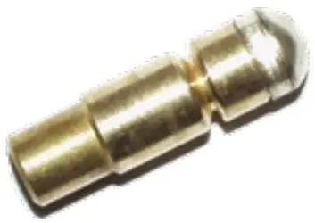
SELECT PINS AND RINGS
- Select brazing pins and ceramic rings to match the specifications of the bonding cable you selected.
CHANGING PIN AND RING HOLDER
- Check that the pin holder and ring holder on the gun are the correct sizes for the brazing pins and ceramic rings you selected. If the sizes are incorrect, the pin holder and ring holder can be changed as follows:
- The ring holder is “push fit” onto the gun. To remove it from the gun, simply pull it away.
- The pin holder is threaded onto a threaded shaft in the gun and locked in place with a nut. Place an open
end wrench over the nut and an open end wrench over the flats on the pin holder. While holding the nut in place, unscrew the pin holder counter clockwise.
EP30200 OPERATION
Figure 3. Pin and Ring Holder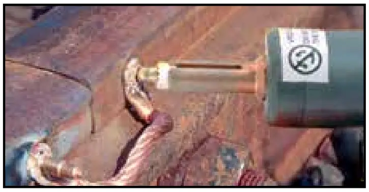
Important
Make sure the correct ferrule and brazing pin are used. The pin braze must be made in the top of the hole when brazing to a vertical surface.
- Hold the gun firmly with both hands and pull the trigger once. The electronics will finish the braze automatically.
- Hold the gun in place for 3-4 seconds after the brazing is complete to allow for cooling. Then remove the gun straight backwards, without pulling trigger.
- After the braze has cooled, knock the shank off the brazing pin using a hammer.
- Use a new ceramic ring for each new pin braze.
Note: A red light indicates low batteries on the unit. Charge as soon as possible.
TROUBLESHOOTING
| PROBLEM | CAUSE | SOLUTION |
| Brazing pin does not ignite or does not ignite long enough. | Batteries not charged or are defective. | Test batteries for proper charge. Replace and/or charge as necessary. |
| Blown fuse. | Check fuses. | |
| Magnetic ground faulty. | Ensure the grounding surface is clean. Check magnetic ground cable and plug for damage. | |
| Faulty cables. | Check gun cables and plugs for damage. | |
| Bonding surface contaminated. | Check that the brazing surface is ground clean. | |
| Braze is faulty. | Batteries not charged or are defective. | Test batteries for proper charge. Replace and/or charge as necessary. |
| Incorrect PIN TYPE setting. | Check PIN TYPE setting on the control box. | |
| Magnetic ground faulty. | Ensure the grounding surface is clean. Check magnetic ground cable and plug for damage. | |
| Bonding surface contaminated. | Check that the brazing surface is ground clean. | |
| Incorrect grinding wheel is used. | Use only Tyrolit grinding wheels or carbide burr. | |
| Ceramic ring was not positioned square to the lug. | Ensure ring is positioned correctly. | |
| Brazing pin not positioned correctly in lug hole. | Ensure pin is positioned correctly. |
EQUIPMENT MAINTENANCE & CARE
Notice
In addition to the Safety Precautions in this manual, observe the following for equipment protection and care.
- Check that the pin holder is not burnt or not holding the pin tightly. Remove the ring holder, clean all the parts and squeeze the fingers of the pin holder together.
- Check the cables on the gun for damage. Replace as required.
- Check that the lift level is correct with the lift level tool.
- Always store the tool in a clean dry space, safe from damage or pilferage.
- Always keep critical equipment markings, such as warning stickers and tags, legible.
- Equipment repair should be performed by experienced personnel only.
- Do not use the equipment for applications for which it was not intended.
SPECIFICATIONS
EP30200
- Voltage: 36V DC
- Approximate Number of Brazings per Battery Charge : 40-60
- Weight: 44 lbs / 20 kg
- Overall Length: 12.5 in. / 315 mm
- Overall Width: 8.75 in. / 220 mm
- Overall Height: 16 in. / 400 mm
ACCESSORIES
| ItemNo. | Part No. | Qty | Description |
| 1 | 72974 | 1 | Carrying Case |
| 2 | EP30K110 | 1 | Pin Brazing Kit, 110vac. Kit Includes: BG10100 pin brazing gun, EP30200 pin brazing unit, DCG426M2 DeWalt grinder kit, battery charger, 3 batteries, 73358 carbide burr. |
| 3 | 35866 | 1 | Battery Charger |
| 4 | 40409 | 3 | Battery, Genesis 16 amp, 12v |
| 5 | 72776 | 4 | Non-spillable Battery Label |
| 6 | 73358 | 1 | Carbide Burr SF-5 |
| 7 | EP30200 | 1 | Medium Duty Elec. Pin Brazing Unit (No Gun) |
| 8 | BG10100 | 1 | Pin Brazing Gun |
| 10 | EP30K12110 | 1 | Pin Brazing Kit 110V/12VDC. Kit Includes: BG10100 Pin brazing gun, EP30200 pin brazing unit, DCG426M2 DeWalt grinder kit, extension cables, battery charger, 3 batteries, 800 Watt inverter, carrying case, 73358 carbide burr. |
| 11 | 73358 | 1 | Carbide Burr (1/4 in. Shank) |
| 12 | 72974 | 1 | Carrying Case |
| 13 | 35818 | 1 | Extension Cable for S4 Pistol |
| 14 | 35819 | 1 | Extension Cable for Earth 5m |
| 15 | 35866 | 1 | Battery Charger |
| 16 | 40409 | 3 | Battery, Genesis 16A 12V (3) |
| 17 | 84936 | 1 | Inverter 1000 Watt |
| 18 | 72776 | 1 | Non-spillable Battery Label |
| 19 | EP30200 | 1 | Medium Duty Elec. Pin Brazing Unit |
| 20 | BG10100 | 1 | Pin Brazing Gun |
| 1 | 35835 | 1 | 8mm | 35832 |
|
| 2 | 35836 | 1 | 8mm with extra silver | 35832 | |
| 3 | 35837 | 1 | 9.5mm | 35833 | |
| 4 | 35840 | 1 | M8/12 threaded | 35834 | |
| 5 | 35841 | 1 | M10 threaded | 35834 | |
| 6 | 35839 | 1 | M12 threaded | 35834 |
CERAMIC RINGS
| Item No. | Part No. | Qty | Description | |
| 7 | 35832 | 1 | 8mm |  |
| 8 | 35833 | 1 | 9.5mm | |
| 9 | 35834 | 1 | 12mm |
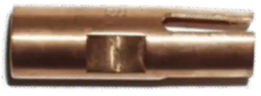
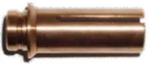
PIN & RING HOLDERS
| ItemNo. | Part No. | Qty | Description | |
| 10 | 35826 | 1 | Pin Holder for Pin brazing, 8-9,5 mm brazing pins. |
|
| 11 | 35827 | 1 | Pin Holder for Pin brazing, M8 Threaded pins. | |
| 12 | 35828 | 1 | Pin Holder for Pin brazing, M10 Threaded pins. | |
| 13 | 35829 | 1 | Pin Holder for Pin brazing, M12 Threaded pins. | |
| 14 | 35825 | 1 | Extended pin and ring holder set for 8-9,5 mm brazing pins. |
|
| 15 | 35830 | 1 | Ring Holder, 8-9,5 mm ceramic rings. | |
| 16 | 35831 | 1 | Ring Holder, M8/M10/M12 mm ceramic rings. |
CABLE LUGS
| Item No | Part No. | Qty | Description | Brazing Pin Required | |
| 17 | 47523 | 1 | Braze Lug for 25 mm Cable | 35836 |
|
| 18 | 47524 | 1 | Braze Lug for 35 mm Cable | 35836 | |
| 19 | 47525 | 1 | Braze Lug for 50 mm Cable | 35836 | |
| 20 | 39241 | 1 | Cable Shoe #6 | 35836 x2 |
|
| 21 | 35847 | 1 | Cable Shoe 10 mm | 35835 | |
| 22 | 35855 | 1 | Cable Shoe D=8 mm | 35836 | |
| 23 | 47526 | 1 | Cable Lug for 16 mm Cable | 35835 |
|
| 24 | 47527 | 1 | Cable Lug for 25 mm Cable | 35836 | |
| 25 | 47528 | 1 | Cable Lug for 35 mm Cable | 35836 | |
| 26 | 47529 | 1 | Cable Lug for 50 mm Cable | 35836 | |
| 27 | 47522 | 1 | Cable Lug 5/8” ground rod to #2 cable | 35836 x2 | |
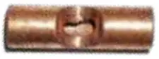
| 28 | 47521 | 1 | Braze Sleeve #6 to #6 | 35836 |
|
| 29 | 41625 | 1 | Multi-Wire Track Connection | 35836 x2 | |
| 30 | 67122 | 1 | Brazing Clip (Secures Wire to Rail) | 35835 |  |


BONDING CABLE WITH LUGS (for pin brazing)
| Item No. | Part No. | Qty | Description | Brazing Pin Required | |
| 31 | 35845 | 1 | Contact Bond / 50 mm², 185 mm long, copper | 35837 |
35844 Pictured |
| 32 | 35844 | 1 | Contact Bond / 25 mm², 145 mm long, copper | 35835 | |
| 33 | 39243 | 1 | 3/16 Bond, 300 mm long | 35835 | |
| 34 | 39244 | 1 | Bond 25 mm², 200 mm long | 35835 | |
| 35 | 37944 | 1 | Rail Bond 50 mm², 185 mm long | 35836 | |
| 36 | 39705 | 1 | Bond Wire 16” OAL x 25 mm | 35835 |
39242 Pictured |
| 37 | 39706 | 1 | Bond Wire 24” OAL x 25 mm | 35835 | |
| 38 | 39707 | 1 | Bond Wire 36” OAL x 25 mm | 35835 | |
| 39 | 39242 | 1 | 3/16 Bond Crimp-able Sleeve | 35835 | |
| 40 | 40366 | 1 | Signal Extension Bond 3/16” (170 mm) | 35835 |
40366 Pictured |
| 41 | 40091 | 1 | Signal Extension Bond 150 mm L=430 | 35837 | |
| 42 | 40090 | 1 | Signal Extension Bond 2 x 35 mm – 2 x L=170 | 35836 | |
| 43 | 41635 | 1 | 3/16 Signal Bond Wire W/Eye & Crimp-able sleeve, 24” long. | 35835 |
|
| 44 | 41815 | 1 | 3/16 Bond 12’ Long Eyelet one end, AL block for T.I.G. Weld Other End | 35835 | |
| 45 | 43686 | 1 | Extension Bond CU, 25 mm², x 330 mm Long | 35835 | |
| 46 | 43519 | 1 | 3/16 Extension Bond 12” | 35835 | |
| 47 | 41225 | 1 | Bond Wire 34” Long C/L-C/L W/9 mm eyelets on both ends | 35835 | |
| 48 | 41226 | 1 | Bond Wire 46” Long C/L-C/L W/9 mm eyelets on both ends | 35835 | |
| 49 | 66579 | 1 | 25mm2 x 500mm Extension Bond | 35835 | |
| 50 | 66580 | 1 | 25mm2 x 900mm Extension Bond | 35835 | |
| 51 | 66269 | 1 | Signal Bond 3/16” x 6’ Braze Lug Both Ends | 35835 | |
| 52 | 67634 | 1 | Railbond 300 mcm L=330 mm Uninsulated (4) 9.5 Pins Required | 35837 |
67634 Pictured |
| 53 | 73652 | 1 | Railbond 300 mcm L=430 mm Use with 4X Pins | ||
| 54 | 73016 | 1 | Railbond 300 MCM | ||
| 55 | 72988 | 1 | Railbond 3/16, 4 in. Reversed (50 pack) | ||
| 56 | 72989 | 1 | Railbond 3/16, 6 in. Reversed (50 pack) | ||
| 57 | 67635 | 1 | Extension Bond 300 mcm x 200 mm crimp, 2) 9.5 Pins Required | 35837 |
67635 Pictured |
| 58 | 47530 | 1 | Bungalow Grounding Bond 3/16” | 35836 | |
| 59 | 80784 | 1 | Railbond 95mm², L=155mm, bare copper | 35837 | |
| 60 | 81167 | 1 | Railbond 95mm², L=155mm 60°, bare copper | 35837 | |
| 61 | 80785 | 1 | Railbond 95mm², L=255mm, bare copper | 35837 | |
| 62 | 81168 | 1 | Railbond 95mm², L=255mm 60°, bare copper | 35837 | |
| 63 | 80786 | 1 | Railbond 95mm², L=355mm, bare copper | 35837 | |
| 64 | 81169 | 1 | Railbond 95mm², L=355mm 60°, bare copper | 35837 |
 41635 Pictured
“T” CONNECTIONS (for pin brazing)
| Item No. | Part No. | Qty | Description | Brazing Pin Required | |
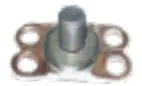
| 65 | 35857 | 1 | Type C Copper Plate with M8 x 18 Brass Threaded Stud T-Bolt | 35835 x2 |
|
| 66 | 35861 | 1 | Type D Copper Plate with M16 x 32 Stainless Steel Threaded Stud T-Bolt | 35837 x4 |
|

GRINDER ABRASIVES
| Item No. | Part No. | Qty | Description | |
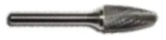
| 67 | 73358 | 1 | Carbide Burr (1/4” Shank) |
|
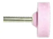
| 68 | 35810 | 1 | Grinding Wheel – NOT for SafeBonding! |
|
| 69 | 73052 | 1 | Bull Nose Stone, 2” (1/4” Shank) |
|

GRINDER
| Item No. | Part No. | Qty | Description |
| 71 | DCG426M2 | 1 | Cordless Grinder Kit. Includes (2) Battery (1) Charger. |

COLD WEATHER ACCESSORIES
| Item No. | Part No. | Qty | Description |
| 71 | 82788 | 1 | Instant Hot Packs, 5” x 9”, 24 Pack |
| 72 | 82789 | 1 | Heat Pack, Body Warmer, 240 ct. |
| 73 | DHX165 | 1 | Electric Heater, 120V |
REPLACEMENT PARTS
| Item No. | Part No. | Qty | Description |
| 74 | 88916 | 1 | Front Piece for SB4 & SB15 Brazing Guns |
FUSES, CHARGERS & BATTERIES
| Item No. | Part No. | Qty | Description | |
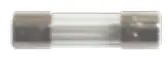
| 75 | 56557 | 1 | Fuse, PCB EP30/60 |
|
| 76 | 56558 | 1 | Fuse, Grinder Outlet EP30 | |
| 77 | 56559 | 1 | Fuse, Control Cable EP30 | |
| 78 | 35866 | 1 | Charger 36 VDC 7 AMP EP30/60 W/ Special DC plug. |
|
| 79 | 84936 | 1 | Inverter 1000 Watt | |
| 80 | 40409 | 1 | Battery 16 AMP 12 Volt EP30 |
|
| 81 | 82877 | 1 | EP30 Cart |


CABLES
| Item No. | Part No. | Qty | Description | |
| 82 | 35820 | 1 | Extension Cable for Grinding |
|
| 83 | 35819 | 1 | Extension Cable for Ground |
|
| 84 | 41768 | 1 | Adapter, Charging |
|
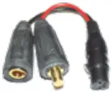
| 85 | 62214 | 1 | Pigtail Charge Adapter |
|
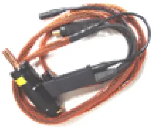
| 86 | 66266 | 1 | Ground Clamp Assembly (Vise Grip Style) |
|


| Item No. | Part No. | Qty | Description | |
| 87 | 72999 | 1 | Econnect Ground Magnet (Magnetic ground for econnect kit) | |
| 88 | 35818 | 1 | Extension Cable for S4 Brazing Gun | |
| 89 | 35816 | 1 | Standard Cable for S4 Pistol 2.7m/8.8ft | |
| 90 | 35817 | 1 | Long Cable for S4, 4.5m/14.75ft |
GUNS
| Item No. | Part No. | Qty | Description | |
| 91 | BG10100 | 1 | Pin Brazing Gun |
|
| 92 | BG10101 | 1 | Angle Head Gun |
|
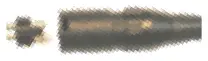
| 93 | 35823 | 1 | Plug Male Grinder 4-Pin |
|
| 94 | 65831 | 1 | Plug Male Controller Gun 3-Pin |
|
| 95 | 66696 | 1 | Plug Male Power Supply Gun Cable |
|
| 96 | 66697 | 1 | Plug Male Ground Cable |
|
| 97 | 56556 | 1 | Charger/Generator Plug |
|


| Item No. | Part No. | Qty | Description |
| 98 | 37946 | 1 | Hole Punch Tool 9.5mm |
| 99 | 35824 | 1 | Hole Punch Tool 8.0mm |
| 100 | 62394 | 1 | Lift Height Tool BG10100 Pin Braze Gun |
EP30 PARTS ILLUSTRATION
INTERNAL ELECTRONIC CONTROL BOX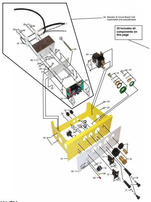
EP30 PARTS LIST
| Item | Part No. | Qty | Description |
| 01 | 66838 | 1 | FRAME EP30 |
| 02 | 66846 | 1 | LABEL EP30 |
| 03 | 66839 | 1 | CIRCUIT BOARD |
| 04 | 66018 | 1 | RELAY |
| 05 | 66840 | 1 | CIRCUIT BOARD MOUNTING PLATE |
| 06 | 66841 | 1 | RESISTOR MOUNTING PLATE |
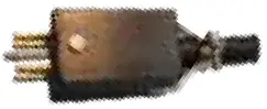
| 07 | 66698 | 1 | SHUNT RESISTOR ASSY W/CABLE |
| 08 | 66843 | 1 | YELLOW LED LENS |
| 09 | 66844 | 1 | RED LED LENS |
| 10 | 66694 | 1 | KNOB FOR ROTARY SWITCH |
| 11 | 66695 | 2 | ROTARY SWITCH |
| 12 | 66691 | 1 | GRINDER RECEPTACLE |
| 13 | 65830 | 1 | GUN CONTROL RECEPTACLE |
| 14 | 66847 | 1 | FUSE BRACKET 5×20 |
| 15 | 66692 | 1 | GUN POWER SUPPLY RECEPTACLE |
| 16 | 66693 | 1 | GROUND RECEPTACLE |
| 17 | 56558 | 1 | FUSE FOR GRINDER 15A |
| 18 | 56559 | 1 | FUSE 1A |
| 33 | 56557 | 1 | GLASS FUSE FOR PCB |
| 34 | 66845 | 1 | RESISTOR & CIRCUIT BOARD UNIT (As shown on previous page outlined by black line). |
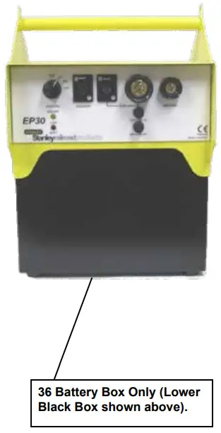
| 35 | 66131 | 1 | EP30 ELECTRONIC BOX Complete unit as shown on previous page. |
| 36 | 35801 | 1 | Battery Box |