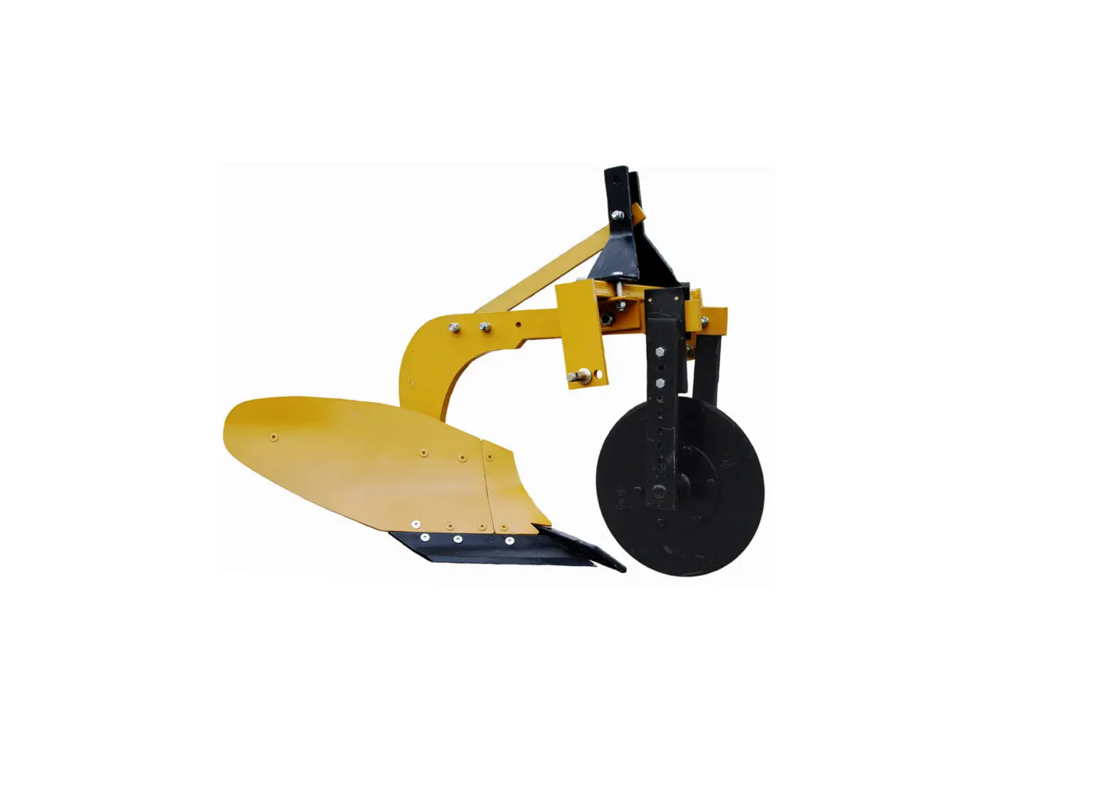
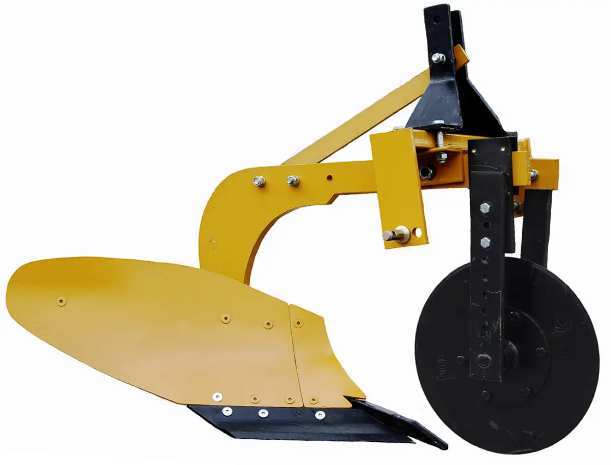
BRABEREQ BE-P1BFK Fixed Mould Board Plough
CONGRATULATIONS
You have invested in one of the best implements of its type in the market today. The care you give your BE AG & INDUSTRIAL implement will greatly determine your satisfaction with its performance and its service life. A careful study of this manual will give you a thorough understanding of your new implement before operating.
If your manual is lost or destroyed, BE AG & INDUSTRIAL will be glad to provide you a new copy. Visit to nearest dealership & get a copy. Most of our manuals can also be downloaded from our website at www.brabereq.com.
As an authorized BE AG & INDUSTRIAL dealer, we stock genuine BE AG & INDUSTRIAL parts which are manufactured with the same precision and skill as our original equipment. Our trained service persons are well informed on methods required to service BE AG & INDUSTRIAL equipments and are ready to help you. Should you require additional information or assistance, please contact us.
TO THE PURCHASER
This manual contains valuable information about your new BE AG & INDUSTRIAL mini rotary tiller. It has been carefully prepared to give you helpful suggestions for operating, adjusting, servicing and ordering spare parts.
Keep this manual in a convenient place for quick and easy reference. Study it carefully. You have purchased a dependable and sturdy mini rotary tiller but only by proper care and operation you can expect to receive the service and long life designed and built into it.
Sometime in the future your mini rotary tiller may need new parts to replace which are worn out or broken. If so, go to your dealer and provide him equipment’s detail like model and part number.
USER RESPONSIBILITY
- Read and understand the information contained in this manual.
- Operate, lubricate, assemble and maintain the equipment in accordance with all instructions and safety procedures in this manual.
- Inspect the equipment and replace or repair any parts that are damaged or worn out which under continued operation would cause damage, wear to other parts, or cause a safety hazard.
- Return the equipment or parts to the authorized dealer, from where it was purchased, for ervice or replacement of defective parts that are covered by warranty. (The BE AG & INDUSTRIAL Factory may inspect equipment or parts before warranty claims are honored.)
- All costs incurred by the dealer for traveling to or transporting the equipment for warranty inspection and claims will be borne by the customer.
TECHNICAL DATA
INTRODUCTION
This handbook contains the use and maintenance instructions with a list of the spare parts of the mould board plough. This M.B. plough is equipped with heavy-duty box frame specially designed for deep ploughing/land preparation of rough soil. It is designed to work in all types of soil for basic functions such as soil breaking, soil raising and soil turning. It can handle the toughest ploughing job with outstanding penetration performance. Regular and satisfactory operations together with economic and long lasting use of the implement depend on the compliance with instructions given in this handbook. Compliance with the instructions in this handbook is also important since Manufacturer declines all and every responsibility for damage to persons or property caused by negligence and failure to comply with these instructions.
USAGE INSTRUCTIONS
BEFORE USE
Before mounting the M.B. plough make sure that all nuts and bolts are properly secured.
ATTACHING THE PLOUGH TO THE TRACTOR
- Place the plough duly leveled on even land.
- Bring the tractor backwards to the plough (don’t drag the plough towards the tractor).
- Attach the left arm of the tractor to the plough first.
- Attach the central arm to the plough. To attach, turn the screws on both sides to an equal length. If the arm is too short or too long, turn the screw to adjust both simultaneously until aligned with the hole on the central arm.
- To attach the lower right arm, turn the screw until the mounting pin is at the same level as the hole on the tractor arm. If the gap between hole and mounting pin is too close or too distant, turn the control arm in or pull it away to an appropriate distance respectively. You may have to adjust both height and distance at the same time.
When the hole at tractor arm and mounting pin are at even levels, insert the pin in the hole and lock it with the lynch pin. - After attaching the plough lift it and adjust the control arm parallel to the ground.
When you look from both rear or sideways, the points should all be touching the ground uniformly.
NOTE:
The plough will work best when the right wheel of the tractor is inside the previously ploughed furrow i.e., when the plough will be in one of the furrow. Readjust the plough alignments if need be. The first bar point will pick up a lot or a little soil depending on how far or near the rear wheel is to the furrow respectively
TRACTOR PREPARATION
INSTRUCTIONS FOR TRACTOR PREPARATION
The following are typical instructions for preparing a tractor for operation.
- The horsepower of tractor selected should match that of the implement.
- Adjust the front and rear wheel track width.
- Provide adequate front end ballast for tractor stability.
- All plough adjustment should be carried out.
- Select load and depth control setting according to tractor operator’s manual.
ADJUSTMENTS
In order to get better results, the following adjustments are necessary.
- Cutting Angle Adjustments
Provision is given in the plough standard for the adjustment of the horizontal angle and vertical tilt angle to obtain optimum point operation in various soil conditions. Tilt ranges from 100 – 150. Increasing the tilt angle improves point penetration in heavy, sticky soils. Decreasing the tilt angle improves point penetration in loose and brittle soils. - Leveling the plough
The level of the plough is controlled by the tractor top link. If the rear end of the plough beam is higher than the front end of the beam, extend the top link. If rear end of the plough beam is lower than the front end, then shorten the top link. Lateral leveling is controlled by adjusting the length of the tractor right lower link. These adjustments must be made with the plough prior to operation.
WARNING FOR DRIVER
- Before ploughing check all the nuts and bolts of the M.B. plough.
- Don’t plough on stony soil.
- Tractor should be in high first gear.
- If soil is hard then plough the field at least twice.
- Lift the M.B. plough on every turn.
- Be vigilant about the tree roots and stones.
- Keep proper distance from M.B. plough when working.
- Lift the plough before approaching the road.
DANGER
Before ploughing with M B plough make sure that nobody stands near it.
DRAFT OF THE M.B. PLOUGH
The type of the soil is the greatest external factor to be considered in drafting of any plough. In very hard ground, it is often necessary to add weight to the wheels to force the plough into the soil.
The bearing conditions of the bearing housing will also affect the draft. Keep bearing in smooth conditions i.e. apply the grease whenever necessary.
Draft is affected by the depth and width of cut per bottom for complete plough too.
Speed is also another factor which increases the draft, doubling the speed increases the draft by about 20 -25%.
ADJUSTMENTS FOR DEEPER PLOUGHING
The depth of the plough can be obtained by the position and draft control levers of the tractor hydraulic system. However more depth can be obtained by:
- Adding extra weight to the plough.
- Reducing or increasing, as per the soil, the tilt angle. A correctly tilted plough tends to penetrate better.
- If the ground is covered with trash, set the plough in almost vertical position and add weight to the mplough. In such soils notched plough gives better results.
MAINTENANCE
MAINTENANCE INSTRUCTIONS
If you use the M.B. plough on stony land then maintenance also increases. Please follow these rules to get the best results:
- If M.B. plough is new then after first two hours of working tighten all the nut-bolts.
- Check the plough adjustments if the steering is hard.
- After every fifty hours of use tighten all nuts and bolts.
- Regularly check for loose nuts and bolts.
- Sharpen the bar point and blades if the blades are blunt as they increase the draft considerably.
STORAGE AFTER WORK
- Clean the M.B. plough after work
- Replace the worn out nuts and bolts.
- If the M.B. plough is not to be used for long time then apply a layer of used oil for rust prevention after cleaning it.
These steps will increase the life of your M.B. plough.
INSTRUCTION FOR DRIVER
- When M.B. plough is ready to use don’t stand between M.B. plough & the tractor.
- Properly fit the three point linkage as mentioned above & lock with the lynch pin.
- Never turn or reverse the tractor when the plough is engaged in the soil.
EXPLODED VIEW & PART LISTS
Fixed Mould Board Plough (USA Type) 1 Bottom
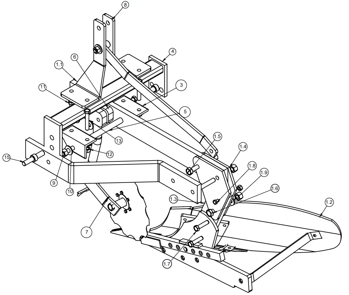
| REF | DESCRIPTION | PART NO | QTY |
| 1 | TINE MOULDBOARD ASSEMBLY | 71200052 | 1 |
| 1.1 | SMALL FLAT(100X25X980 L) | 71200046 | 1 |
| 1.2 | BIG MOULD BOARD ASSEMBLY-USA TYPE | 71200061 | 1 |
| 1.3 | BOTTOM FURROW FLAT | 71200048 | 1 |
| 1.4 | JOINTER PLATE | 71200047 | 2 |
| 1.5 | HEX HEAD BOLT M18X110X2.5MM (10.9 GRADE) | 10260318 | 2 |
| 1.6 | HEX HEAD BOLT 18X75X2.5MM (GRADE 8.8) | 10260375 | 1 |
| 1.7 | HEX HEAD BOLT 16X65X2MM (8.8 GRADE) | 10260378 | 3 |
| 1.8 | HEX HEAD BOLT 12X70X1.75MM (8.8 GRADE) | 10260407 | 1 |
| 1.9 | SPRING WASHER 18 MM | 10270006 | 3 |
| 1.10 | SPRING WASHER 16 MM | 10270005 | 3 |
| 1.11 | NYLOCK NUT M18X2.5MM | 10280020 | 3 |
| 1.12 | NYLOCK NUT M16X2MM | 10280005 | 3 |
| 1.13 | SPRING WASHER 12 MM | 10270003 | 1 |
| 1.14 | NYLOCK NUT M12X1.75 (P) | 10280025 | 1 |
| 2 | MIDDLE JOINTER MB PLOUGH 1 BOTTOM | 71200053 | 1 |
| 3 | CONNECTING ANGLE 75X75X10X150L- ONE BOTTOM USA | 71200017 | 2 |
| 4 | DRAWBAR ASSEMBLY USA TYPE | 71200011 | 1 |
| 5 | CONNECTING ROD Ø25X425 L | 71200015 | 1 |
| 6 | COLTER HOLDING BRACKET (ROUND ROD) | 71200013 | 2 |
| 7 | COLTER ASSEMBLY MB PLOUGH.(USA TYPE) | 79490012 | 1 |
| 8 | 3-POINT LINKAGE ASSEMBLY (25MM) MOULD BOARD PLOUGH 1-BOTTOM (USA TYPE) | 71210018 | 1 |
| 9 | NYLOCK NUT M18X2.5MM | 10280020 | 2 |
| 10 | SPRING WASHER 18 MM | 10270006 | 2 |
| 11 | HEX HEAD BOLT M16X90X2MM (8.8 GRADE) | 10260393 | 4 |
| 12 | NYLOCK NUT M16X2MM | 10280005 | 6 |
| 13 | SPRING WASHER 16 MM | 10270005 | 6 |
| 14 | HEX HEAD BOLT M16X125X2MM (8.8 GRADE) | 10260367 | 2 |
| 15 | HITCH PIN 20MM | 10020013 | 2 |
COLTER ASSEMBLY
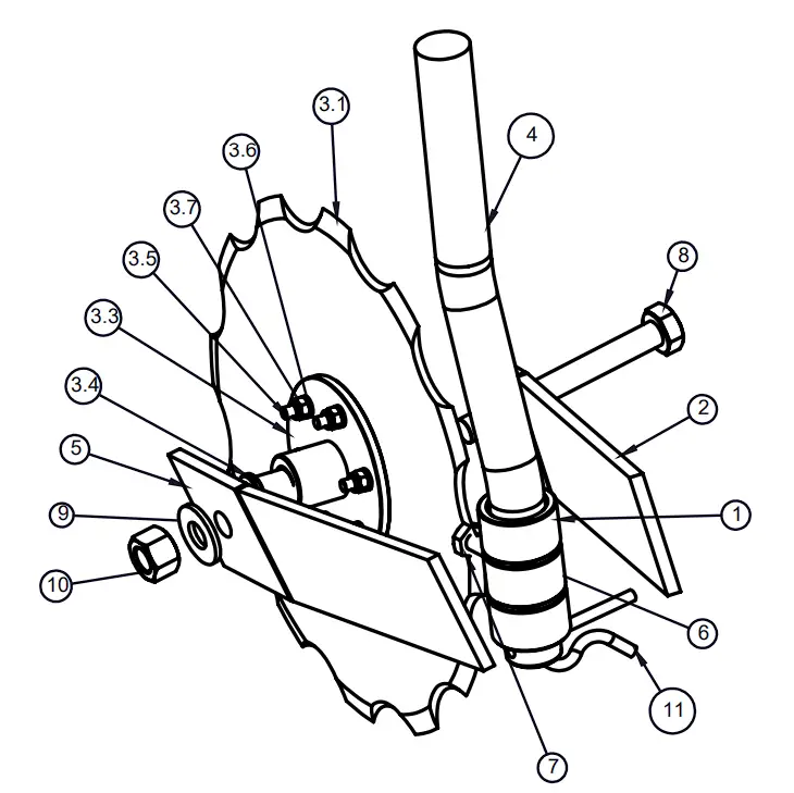
| REF | DESCRIPTION | PART NO | QTY |
| 1 | COLTER ROD HOLDING BUSH | 79490016 | 2 |
| 2 | COLTER FLAT L.H.S (ROUND TYPE) | 79490014 | 1 |
| 3 | COLTER DISC ASSEMBLY | 79490002 | 1 |
| 3.1 | HI CARBON PLAIN DISC 14”X4MM | 10240093 | 1 |
| 3.2 | COLTER DISC BUSH | 79490003 | 1 |
| 3.3 | COLTER DISC PLATE | 79490005 | 1 |
| 3.4 | COLTER BUSH NYLON-101 | 79490004 | 2 |
| 3.5 | HEX HEAD BOLT 8X30X1.25MM (8.8 GRADE) | 10260456 | 6 |
| 3.6 | SPRING WASHER 8MM | 10270001 | 7 |
| 3.7 | NYLOCK NUT M8X1.25MM | 10280027 | 6 |
| 4 | EN-BAR Ø 38MMX470(L) | 01100065 | 1 |
| 5 | COLTER FLAT R.H.S (ROUND TYPE) | 79490015 | 1 |
| 6 | COLTER HOLDING THREADED BUSH | 79490017 | 1 |
| 7 | HEX HEAD BOLT M10X25X1.5MM (8.8 GRADE) | 10260361 | 1 |
| 8 | HEX HEAD BOLT M18X160X2.5MM (8.8 GRADE) | 10260402 | 1 |
| 9 | SPRING WASHER 18 MM | 10270006 | 1 |
| 10 | NYLOCK NUT M18X2.5MM | 10280020 | 1 |
| 11 | R PIN 3/8 | 10020076 | 1 |
BRABEREQ.COM
[email protected]
PHONE:604-850-7770
FAX: 604-850-7774
TOLL FREE PHONE: 1-877-588-3311
TOLL FREE FAX: 1-800-665-7334