A-LEGIO SENSE Panel-Mounted Dosing System

PANEL-MOUNTED DOSING SYSTEM – OPERATION AND MAINTENANCE ALEGIO SENSE
FOR OTHER LANGUAGES:

ADSP9000055 11/05/2021 Rev.1.0 1/12
A-POOL TOP EVO PH-CL
1. DESCRIPTION
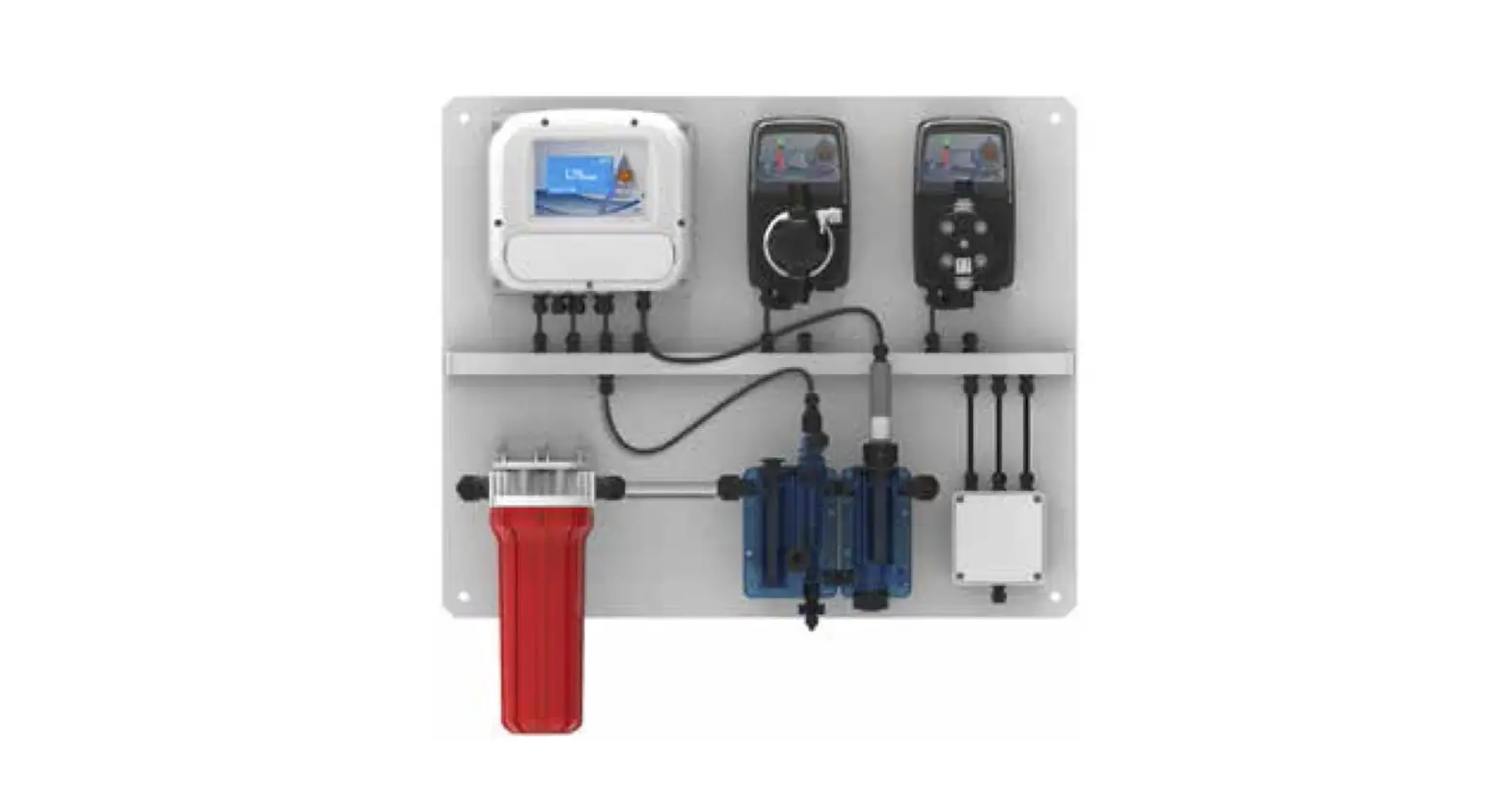
The A-LEGIO SENSE panel has been designed to control the proliferation of legionella and other hydro diffused pathogens through an ON / OFF or proportional dosage of sodium hypochlorite or chlorine dioxide at the same time as a dosage of an anticorrosive conditioner.
In general, it is composed of:
- 1 AE-START + CL instrument for the measurement of free chlorine;
- 1 pump HC151 + (PImA model) to dose an inhibitor (anticorrosive) product controlled by a pulse emitting counter;
- 1 pump HC151 + (PimA model) with automatic air purge to dose a disinfectant product (sodium hypochlorite, etc.) controlled by the AE-START + CL instrument;
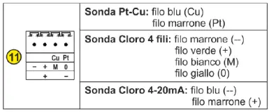
- 1 membrane amperometric probe for the determination of free chlorine;
- 1 modular HT probe holder, proximity sensor and flow regulator;
- 1 HT prefilter.
For the pump managed by the chlorine measuring instrument, the dosage mode set in the factory is the proportional one: the dosage is proportional to two mA values (4mA and 20mA).
1.1 PANEL COMPOSITION
- Panel
- Membrane chlorine probe 0-5ppm
- n. 1 temperature probe (optional)
- HT water filter 9”3/4 complete of AC-HT cartridge 80 micron, 10×14 tube fittings
- Roll of PVC tube 10X14 (4m)
- Controller, pump and panel programming manuals
- n.2 PVDF injection valve
- n.2 PVDF foot filter
- Roll of PE tube for delivery (4 m)
- Roll of PVC tube for suction (4 m)
- Roll of PVC tube for air bleed (4 m)
1.2 TECHNICAL SPECIFICATIONS
Supply: 110-240VAC – 50/ 60Hz
Panel dimensions: L 650 x H 600 x D 250 mm
Max power: 60 W (with pumps in “C” curve)
1.3 OVERALL DIMENSIONS
NB: although devices may be arranged differently on the panel depending on the model selected, the panel’s overall dimensions do not change.
NB: although devices may be arranged differently on the panel depending on the model selected, the panel’s overall dimensions do not change.
1.4 HYDRAULIC SPECIFICATIONS PUMP HC151+
Please refer to the HC151+ pump manual.
1.5 FUNCTIONAL CHARACTERISTICS OF THE AE-START+ INSTRUMENT
Please refer to the AE-START+ instrument manual.
1.6 HC151+ PUMP CONNECTIONS
Please refer to the HC151+ pump manual.
1.7 AE-START+ INSTRUMENT CONNECTIONS
Please refer to the AE-START+ instrument manual.
1.8 COMPLETE MANUALS
The complete manuals are available on:

HC151+ PI-MA

AE-START+
CAUTION: Always disconnect the electrical power supply before servicing the device.
2. PROGRAMMING THE PANEL
After installing and connecting all the required probes and devices for the purchased panel, follow the programming instructions set out in the pump and instrument manuals.
A list summarising the operations to follow for each panel is provided below.
Please refer to the HC151+ pump manual.
Please refer to the AE-START+ instrument manual.
3. PROBE INSTALLATION AND MAINTENANCE
3.1 CL(J) 4-20 mA PROBE
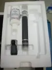
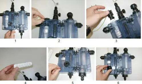
1. Take the CL(J) probe out of the package and unscrew the membrane cap on the lower part of the probe:
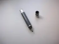
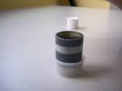
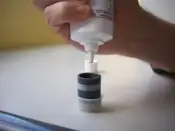
2. Lower the rubber ring on the membrane cap before filling it with the electrolyte gel provided in the package:

3. Immerse the probe in the cap, being careful to prevent any excess electrolyte from spilling over (if so, rinse).
4. Unscrew the top part of the probe and connect the bipolar cable to the probe and the instrument’s CL terminal box:
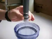
5. Screw the top part back in place and insert the probe in the proper probe holder.
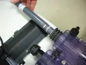
6. Secure the probe in place on the probe holder:
3.2 CL(J) PROBE with mV signal
To fit the CL(J-mV) probe to the modular probe holder, follow the instructions provided for the CL(J) 4-20mA probe; to prepare the probe for use, proceed as follows:
– Remove the protective cap and unscrew the membrane cap from the cell body. – Open the electrolyte bottle, screw the nozzle in place and allow any excess air to come out. – Fill the membrane cap with electrolyte to the level as shown (see figure); avoid the formation of air bubbles as much as you can.
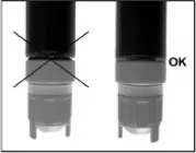
– Eliminate any air bubbles by gently tapping the cap over a flat surface. Position the cell vertically on the filled membrane cap and screw the cap by hand until flush; proceed slowly to avoid damaging the membrane and be careful not to cover the breather hole with your fingers, because excess electrolyte should be free to flow out.
– Remove the electrolyte coming out with a damp cloth or rinse with water.
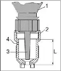
- Electrolyte bottle
- Membrane cap
- Nozzle
- Breather hole
L. Electrolyte fill level
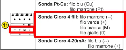
To perform the electrical connections, follow the diagram provided in the instrument’s manual.
3.3 CLEANING THE PROBE HOLDER FILTER
1) Close the valve.
2) Remove the fork.
3) Extract the filter.
4) Pull the filter out and clean it with water.
5) Unscrew the breather plug and the cap.
6) Allow water to run through the probe holder until free of debris and dirt.
7) Fit everything back in place.
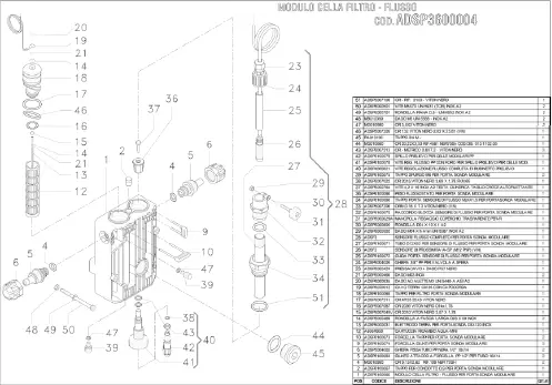
EXPLODED VIEW
![]()
MANUALE D’USO E MANUTENZIONE PANNELLO DOSAGGIO A-LEGIO SENSE FOR OTHER LANGUAGES:


