![]()
Arendi Products GmbH
Eichtalstrasse 55 8634 Hombrechtikon Switzerland
BLT2450 User manual
BLT2450 Bluetooth Tester
Release
27. September 2022
Author
Rashid Talib
Copyright
© Arendi
ABT0003_Manual_20220927.docx Hombrechtikon, 30. September 2022
| Date | Author | Change |
| 16.05.2019 | TALIA | 1st draft |
| 24.02.2020 | TARA | Adding diagrams |
| 25.06.2020 | TARA | Updating diagrams, specifications, documentation |
| 13.07.2020 | TARA | Minor changes |
Terms and definitions
| BLT2450 | Arendi Bluetooth Tester |
| DUT | Device Under Test |
| BLE | Bluetooth Low Energy |
| DTM | Direct Test Mode |
| PER | Packet Error Rate [%] |
| dBm | Power level in decibels, relative to 1mW |
| dBc | Power level in decibels, relative to the carrier |
1.1 References
[1] DTM Specification: See Bluetooth Specification Version 4.0, Vol. 6, Part F
Kit content
The kit contains a BLT2450 tester with a suitable USB cable, one 2.4GHz Antenna for Bluetooth and DTM testing, and one 50Ω terminator. 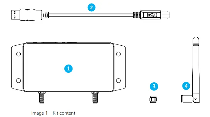
- BLT2450 tester
- USB cable
- Termination, 50.0
- SMA antenna, 2.4 GHz
Features and controls
3.1 User interface
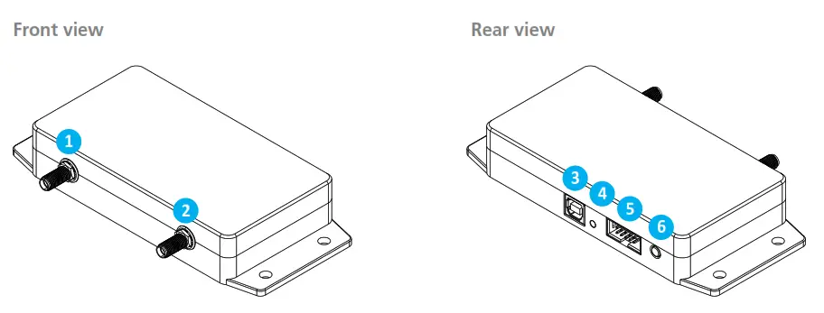
- Primary SMA port
- Secondary SMA port
- USB port
- Power LED
- 10 extension port
- Button, status LED
Image 2 Front and rear view
RF1, primary SMA port
This is the main port used for any of the possible operating modes. Any SMA cable, antenna or adapter can be connected to this port. The primary port is a bidirectional, 50Ω matched RF port.
RF2, secondary SMA port
The secondary port is only used when the BLT2450 is operated in attenuator mode. Make sure to have the 50Ω terminator attached to this port whenever it is unused to reduce interference. The secondary port is a bidirectional, 50Ω matched RF port.
USB-B connector
This port is required to connect the BLT2450 to a PC using the provided USB-B cable. The power LED indicator is lighting up when proper USB power is available, no additional power supply is required.
Power indicator LED
This LED is illuminated when power is provided to the USB-B Port
IO extension port
This port provides IO capabilities such as UART, reserved for future use.
Button, status LED
This illuminated button is intended for user interaction, reserved for future use.
Introduction
The BLT2450 tester was designed to simplify the development and testing process of Bluetooth-capable devices.
It can easily connect to Bluetooth LE peripherals or DUTs running in DTM mode and with the built-in attenuator and power meter blocks the BLT2450 offers several useful testing options. The BLT2450 connects to a PC using a single USB cable and requires no additional power supply. The provided tools and libraries make it easy to get started and build customized software for automated testing.
4.1 Modes of operation
The BLT2450 can be operated in any of the four modes described below:
DTM mode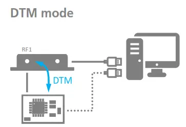
The BLT2450 acts as a DTM master. The PC application controls the transmission of DTM packets between the BLT2450 and the DUT and evaluates the resulting data. The signal of the transmission can be attenuated to facilitate pass / fail verification of the DUT.
DTM mode is suitable for
- PER measurements
- Sensitivity measurements
- DUT RF verification
- DUT pass / fail verification
Power meter mode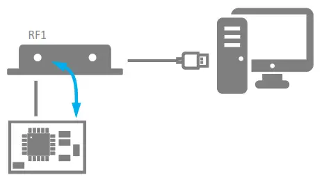
The BLT2450 operates as a RF power meter and measures the power received from the DUT. The
DUT is preferably running in constant carrier mode(CW).
Power meter mode is suitable for
- DUT RF power verification

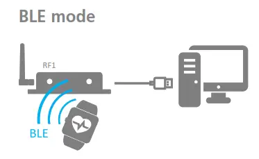
The BLT2450 operates like a BLE dongle. The PC application uses the BLT2450 to communicate with nearby BLE devices. An example for the use of BLE mode is EMC testing where a method is required to continuously observe the operation status of the DUT during the emission test.
BLE mode is suitable for
- Scanning and connecting BLE devices
- DUT RF verification
- EMC test surveillance
- Continuous integration
Attenuator mode 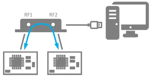
The BLT2450 behaves like a configurable attenuator that can be placed anywhere between two RF devices.
Attenuator mode is suitable for
- General RF testing and developing
Software tools
Visit https://www.arendi.ch/blt2450 to download the latest software tools and documentation. We recommend using the applications that come with the installer to get familiar with the BLT2450 before developing your own tools with the provided libraries.
Calibration
The BLT2450 is calibrated before shipping to guarantee maximal accuracy during operation. Calibrated testers can be replaced by another calibrated tester without the need of adjusting the parameters or threshold of a working test environment.
Regular calibration is recommended to guarantee the long-term stability and accuracy of your test system. Please contact Arendi products GmbH for calibration services.
Performing measurements
7.1 Setup
Testing can be done either “conducted” or “radiated”. In conducted testing, the BLT2450 communicates to the DUT through a coax cable. This solution provides the most reliable and solid testing, but it requires that the DUT has a physical connector which the coax cable can be attached to. If conducted testing is unpractical or not possible, radiated testing is used and the BLT2450 communicates to the DUT using the supplied kit antenna. 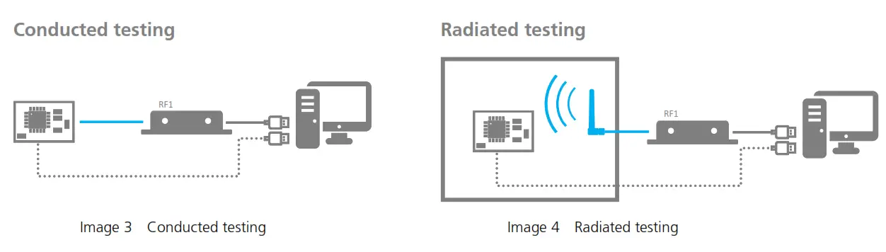
7.1.1 Conducted
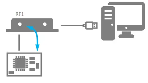
If a conducted connection to the DUT is possible, the setup described in Image 3 is the preferred way of operation because it provides communication with the least interference and usually requires no shielding. Simply connect a suitable coax cable between the BLT2450 and the DUT. Any SMA cables can be connected to the BLT2450 directly.
- Connect the RF1 port to the DUT using a coax cable
- Attach the provided terminator to RF2 port (optional)
- Connect the BLT2450 to the PC using the provided USB-B cable
- Run PC application
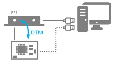
7.1.2 Radiated
If the only radiated connection is possible, consider the setup described in Image 4. Placing the DUT in an RF-shielded environment reduces radio interference with nearby devices such as smartphones or WiFi and eliminates many problems and surprises that cause headaches. Usually, the space within the shielding enclosure is limited and the BLT2450 is placed outside the shielding which is fine.
- Attach the provided antenna to the RF1 port
- Attach the provided terminator to the RF2 port (optional)
- Connect the BLT2450 to the PC using the provided USB-B cable
- Run PC application
7.1.3 Considerations
We highly recommend to either do conduct measurements or use shielding whenever possible. However, there may be situations where conducted measurement or shielding adds to much complexity to the test sequence and is not viable (during production e.g.). In such situations, some measurements may not work reliably because of the physical limitations by nature. We, therefore, recommend to only use the measurements listed below:
- DTM measurement with DUT in Tx mode only
- Power level measurement
7.2 DTM measurement
DTM[1] is a measurement standard used during development and RF qualification to verify that the DUTs RF transceiver is operating properly. During DTM testing, RF test packets are transmitted between BLT2450 and DUT and the number of correctly transmitted packets can be used to calculate the PER. It is required that the DUT is running a DTM firmware which can be controlled by the PC using either a physical or virtual COM port.
- Connect the RF1 port to the DUT. For conducted measurement use an SMA cable, for radiated measurement use the provided antenna. Conducted measurement is preferable but often not possible because the DUT may have no RF connector. In this case, only radiated measurement is possible.
- Attach the provided terminator to the RF2 port (optional)
- Connect the BLT2450 to the PC using the provided USB-B cable
- Connect the DUT to the PC using a physical UART or a UART to USB converter
- Run the DTM application
 7.3 Sensitivity measurement
Sensitivity measurement uses the same setup as DTM measurement but rather than calculating the PER at one setting only, multiple PER measurements are recorded while the signal level between the BLT2450 tester and DUT is continuously reduced. The resulting diagram can be used to find the sensitivity limit of the DUT.
- Use the setup as described in the DTM measurement (chapter 7.2)
- Run the DTM sensitivity application

7.4 Power level measurement
Measuring the output power of the DUT is a good and fast way to verify the correct assembly of the RF components such as filters and antenna matching. If the measured output power is much lower than expected, it’s usually an indicator that filter or matching components are not assembled properly. It is required that the DUT is running firmware capable of producing an unmodulated carrier (CW) on the frequency of interest.
- Connect the RF1 port to the DUT. For conducted measurement use an SMA cable, for radiated measurement use the provided antenna. Conducted measurement is preferable but often not possible because the DUT may have no RF connector. In this case, only radiated measurement is possible
- Connect the BLT2450 to the PC using the provided USB-B cable
- Attach the provided terminator to the RF2 port (optional)
- Set the DUT into CW mode
- Run the power meter application
 Note
Note
Power level measurement measures the total received power on the RF1 port. Other than a spectrum analyzer, the BLT2450 measures the total power of all available signals and does not care about their frequencies. Signals from interferers cannot be distinguished from the DUT signal and may lead to wrong measurements. Use either conducted measurement or a shielding box if this is a concern. Assembling or soldering errors on the DUT can lead to unwanted spurious signals. Power level measurement is not suitable for detecting or measuring these kinds of errors.
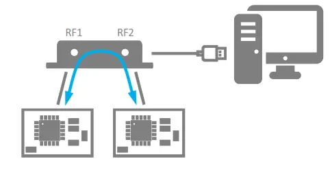
7.5 Digital attenuator mode
Digital attenuator mode is the only mode where the RF2 port is used and is suitable if the communication between any two DUTs should be tested. In attenuator mode the BLT2450 acts like a digital step attenuator.
- Connect the BLT2450 to the DUTs using the RF1 and RF2 ports
- Connect the BLT2450 to the PC using the provided USB-B cable
- Run the digital attenuation application
Specifications
8.1 Mechanical
The BLT2450 is made of a massive aluminum body providing mechanical protection even in harsh environments and shielding from RF power leaking into / out of the enclosure. The enclosure contains four 5.5mm holes which can be used for mounting the BLT2450 using M5 screws.
| Property | Description | Typical |
| width | Width of enclosure only | 65.0 mm |
| Width | Width including SMA connectors | 80.3 mm |
| Length | 150.0 mm | |
| Height | Height without rubber feet | 25.0 mm |
| Weight | 440 g |
Table 1 Mechanical specifications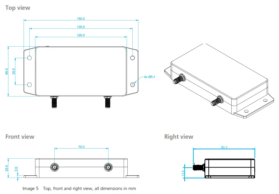
8.2 Electrical
8.2.1 USB
| Property | Description | Min | Max | Typical |
| Supply voltage | Voltage range on the USB connector | 4.5 V | 6.0 V | 5.0 V |
| Current consumption | Current drawn from the USB bus | – | 20 mA | 10 mA |
| Power consumption | Power consumed from the USB bus | – | 100 mW | 50 mW |
Table 2 USB specifications
8.2.2 RF1, RF2
| Property | Description | Min | Max | Typical |
| Impedance | The impedance of RF ports | – | – | 50 Ω |
Table 3 RF1, RF2 specifications
8.2.3 DTM
| Property | Description | Min | Max | Typical |
| Input power | Allowed signal power, applied to RF1 port | – | 10 dBm | – |
| Output power | Power generated at the RF1 port | -120 dBm | 0 dBm | – |
| Step size | Step size of adjustable output power | – | – | 0.25 dB |
| Frequency range 1 | Frequency range covering DTM channels 0 .. 39 | 2’402 MHz | 2’480 MHz | 2’440 MHz |
| Sensitivity | Rx sensitivity at RF1 port with 0.1% BER (30.8% PER), 1Mbps | -89 dBm | -91 dBm | -90 dBm |
| VSWR | RF1 reflection in DTM Rx mode, 2’440 MHz | – | – | 1.4 |
Table 4 DTM specifications
8.2.4 Power Meter
| Property | Description | Min | Max | Typical |
| Input power | Detectable power range (RMS) | -70 dBm | 10 dBm | – |
| Frequency range 2 | Detectable frequency range | 1 MHz | 4’000 MHz | 2’440 MHz |
| VSWR | RF1 reflection at 2’440 MHz | – | – | < 1.9 |
Table 5 Power Meter specifications
1 The BLT2450 DTM mode is calibrated at 2’440 MHz
2 The BLT2450 Power meter is calibrated at 2’440 MHz
8.2.5 Attenuator
| Property | Description | Min | Max | Typical |
| Input power | Input power at RF1 and RF2 | – | 10 dBm | – |
| Insertion loss | Insertion loss between RF1 and RF2 ports | – | – | 8 dB |
| Range | Selectable attenuation between RF1 and RF2 | 0 dB | 120 dB | – |
| Step size | Attenuation step size | – | – | 0.25 dB |
| Frequency range 3 | Operating frequency range | 100 MHz | 6’000 MHz | 2’440 MHz |
| VSWR @ 2’440 MHz | RF1, RF2 reflection at 2’440 MHz | 1.5 | ||
| VSWR | RF1, RF2 reflection over full frequency range | 1.1 | 2 | < 1.8 |
Table 6 Attenuator specifications
8.2.6 DTM Output power
Output Power on RF1 port in DTM constant carrier mode (CW)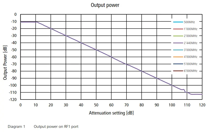
3The BLT2450 attenuator is calibrated at 2’440 MHz
8.2.7 Attenuator linearity
Attenuation between RF1 and RF2 port 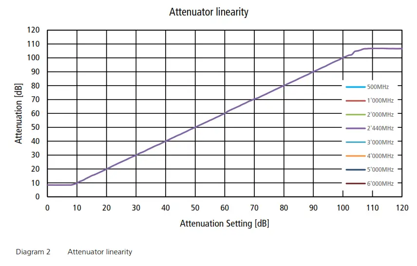
8.2.8 Attenuator error
Attenuation error between RF1 and RF2 port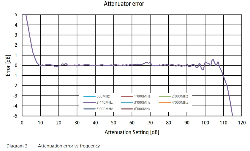
8.2.9 Power Meter linearity
Power meter linearity on RF1 port 
8.2.10 Power Meter error
Power meter error on RF1 port 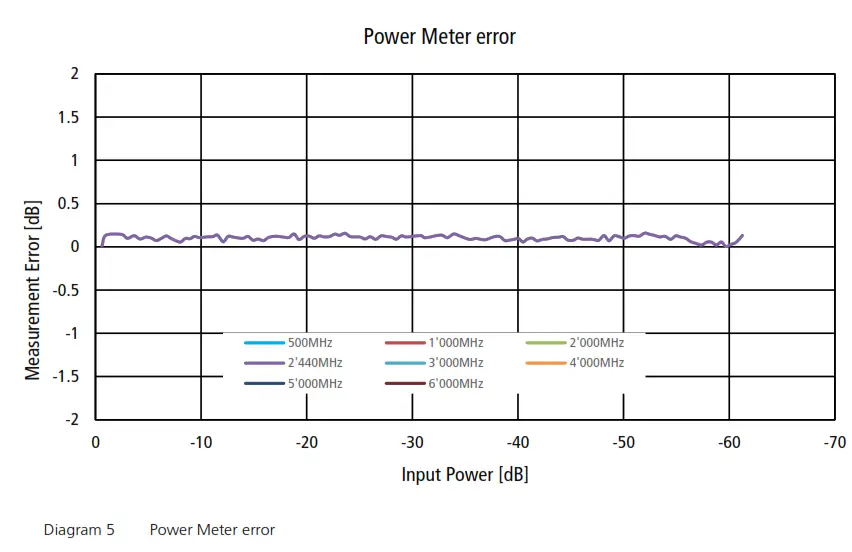
Phone +41 55 254 30 41
Fax +41 55 254 30 31
www.products.arendi.ch


