
![]() PMX AUDIO KIT
PMX AUDIO KIT
BY ROCKFORD FOSGATE®
P/N 2883964
IMPORTANT Due to the technical nature of this kit, Polaris® insists this installation be performed by a certified Polaris® Technician.
APPLICATION
Verify accessory fitment at Polaris.com.
BEFORE YOU BEGIN
Read these instructions and check to be sure all parts and tools are accounted for. Please retain these installation instructions for future reference and parts ordering information.
REQUIRED SOLD SEPARATELY
Only parts for installation of the PMX Audio Kit By Rockford Fosgate® are included. For complete installation, the following additional kit is required (sold separately):
- Base Audio Kit, P/N 2883943
KIT CONTENTS
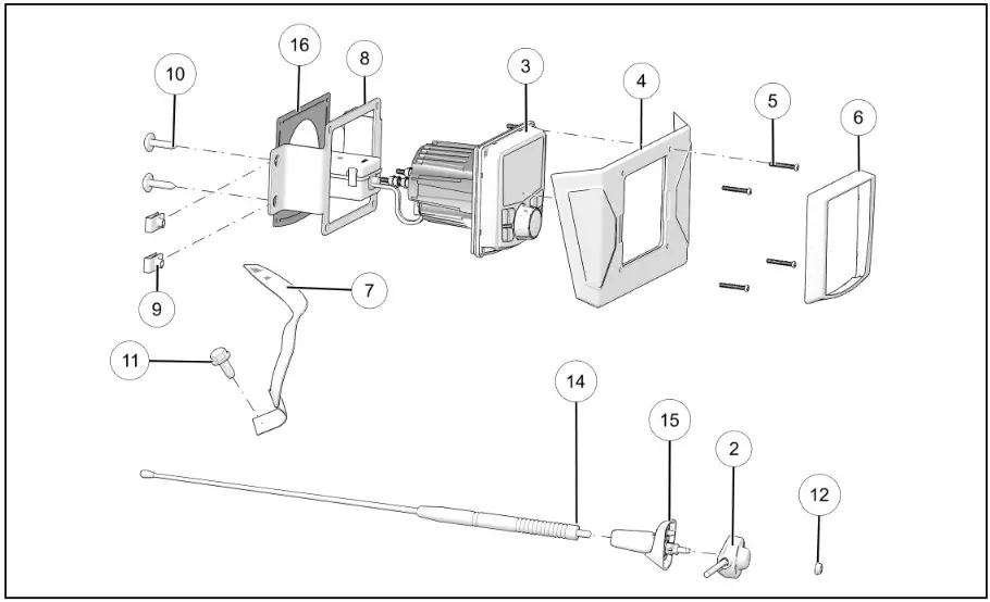
| REF | QTY | PART DESCRIPTION | P/N AVAILABLE SEPARATELY |
| 1 | 1 | Harness—Audio, PMX (see Harness Detail section) | 2414719 |
| 2 | 1 | Assembly—Harness, AM/FM Antenna | 2414727 |
| 3 | 1 | Assembly—Head Unit, PMX | 2637397 |
| 4 | 1 | Panel—Cover, 7 in. Display | 2637662 |
| 5 | 4 | Screw—Hex Button Head, M3.5 x 0.6 mm x 25 mm | n/a |
| 6 | 1 | Cover—PMX, Front | n/a |
| 7 | 1 | Strap—Ground, Antenna, Braided | 4016696 |
| 8 | 1 | Bracket—PMX, Dashboard | 5267727-329 |
| 9 | 4 | Clip—U, Speed Nut | 7081305 |
| 10 | 4 | Screw—Torn® Truss Head, M6 x 1.0 mm x 25 mm | 7519650 |
| 11 | 1 | Screw—Hex Flange, M8 x 1.25 mm x 20 mm | 7520764 |
| 12 | 1 | Nut—Hex Flange, M5 x 0.8 mm | 7547437 |
| 13 | 2 | Cable Tie (not shown) | 7081033 |
| 14 | 1 | Antenna—Mast, AM/FM, Short | 4014849 |
| 15 | 1 | Mount—Antenna, 90° | 4016695 |
| 16 | 1 | Plate—Back, Dashboard Bracket | n/a |
HARNESS DETAIL
HARNESS–AUDIO, PMX P/N 2414719
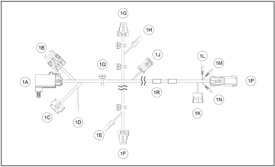
NOTE
Harness Detail graphic is compressed to emphasize detail.
| REF | PART DESCRIPTION | PIN QTY I GENDER | CONNECTS TO | |
| 1A | Fuse Relay Center | n/a | Vehicle Structure | |
| 1B | Connector, Power, Polaris Pulse® | 3 Pin Female | Pulse® terminal block | |
| 1C | Connector, Amplifier, 4 Channel | 23 Pin Female | Amplifier | |
| 1D | Bullet Connector, Ground, Amplifier | 1 Pin Male | Amplifier | |
| 1 E | Connector, Front, Tweeter, Right | 2 Pin Female | Speaker—Tweeter, Right | |
| 1 F | Connector, Front, Driver, Right | 2 Pin Female | Speaker—Driver, Right | |
| 1G | Connector, Front, Driver, Left | 2 Pin Female | Speaker—Driver, Left | |
| 1H | Connector, Front, Tweeter, Left | 2 Pin Female | Speaker—Tweeter, Left | |
| 1J | Connector, Audio, Rear | 4 Pin | 2 Pin Male | Vehicle Structure / Rear Audio |
| 2 Pin Female | ||||
| 1P | Connector, Subwoofer | 8 Pin | 4 Pin Male | Harness—Audio, Subwoofer |
| 4 Pin Female | ||||
| 1R | Tape (2 Locations) | n/a | Identifies installation location for cable tie 13) | |
TOOLS REQUIRED
- Safety Glasses
- Drill
- Drill Bit:
- 3/16 in. (5 mm)
- 1/2 in. (12 mm)
- Pliers, Push Pin Rivet
- Screwdriver Set, Torn®
- Socket Set, Torn® Bit
- Torque Wrench
IMPORTANT
Your PMX Audio Kit By Rockford Fungate® is exclusively designed for your vehicle. Please read the installation instructions thoroughly before beginning. Installation is easier if the vehicle is clean and free of debris. For your safety, and to ensure a satisfactory installation, perform all installation steps correctly in the sequence shown.
INSTALLATION INSTRUCTIONS
VEHICLE PREPARATION
GENERAL
- Shift vehicle transmission into PARK. Turn key to OFF position and remove from vehicle.
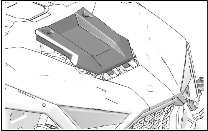
CENTER HOOD PANEL REMOVAL
- Turn two quarter-turn fasteners to loosen center hood panel. Slide panel backwards until tabs clear front hood panel.

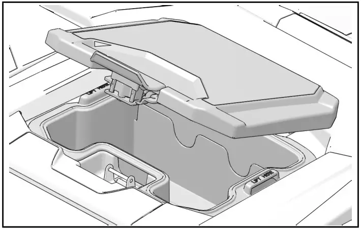
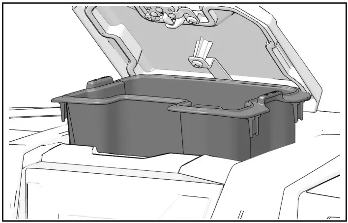
DASHBOARD STORAGE REMOVAL
- Open center dashboard storage compartment.

- Remove storage compartment from dashboard.

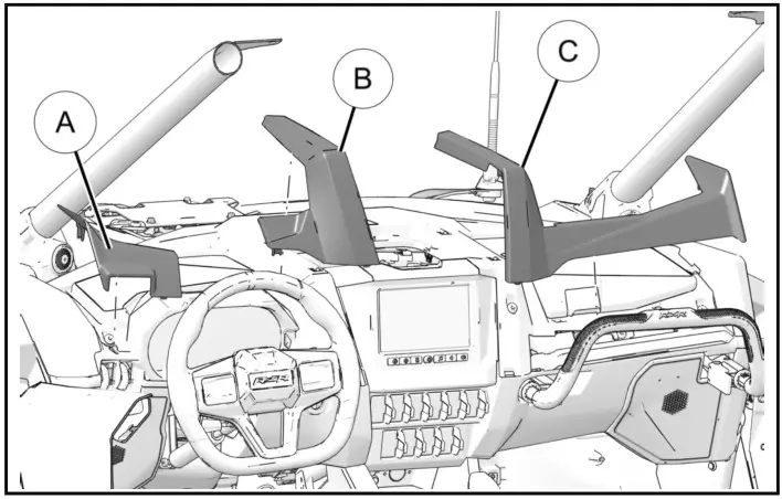
DASHBOARD TOP REMOVAL
- Carefully pull up to remove and retain left A, center B, and right C dash trim pieces.
TIP
Release steering tilt lock for better access.
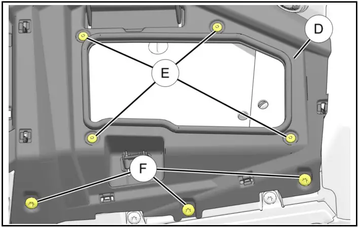
- Open glove box lid. Remove and retain four screws E around glove box opening and three screws F from front of dashboard top D. Make note of different screw sizes.

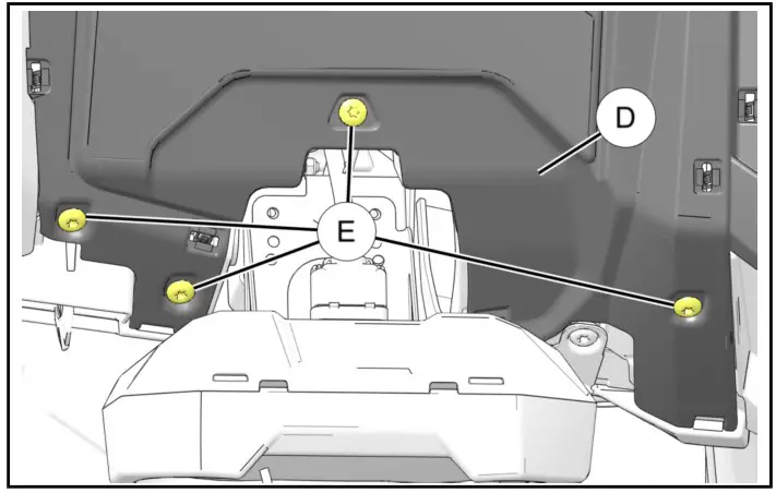
- Tilt steering wheel down. Remove and retain four screws E from dashboard top D.

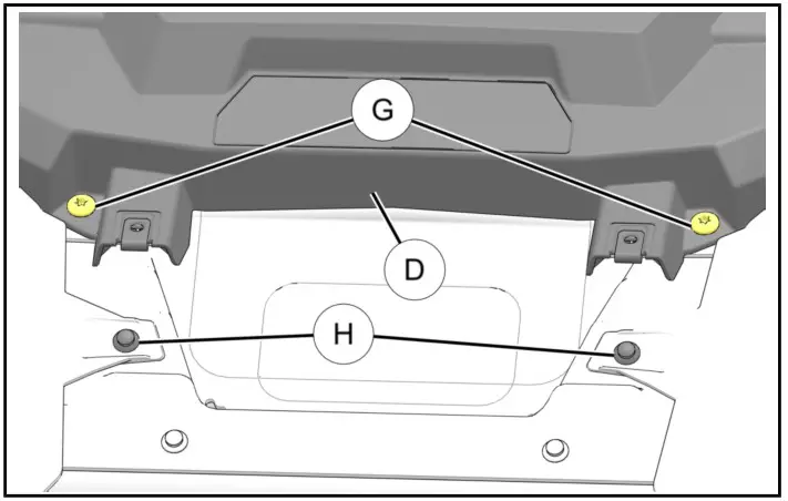
- On front of vehicle, near rear edge of center hood panel opening, remove and retain two screws G from dashboard top D. Remove and retain two pushpin rivets H from front side panels.5. Carefully lift edge of left front fender J to release tab from dashboard top D as shown.
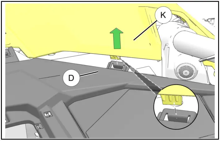
- Carefully lift edge of right front fender K to release tab from dashboard top D as shown.
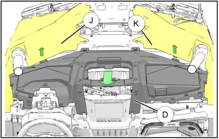
- Carefully keep panels J and K up and away from tabs and remove dashboard top D by tilting rear section up and pulling out toward rear.
TIP
Have a second person to hold panels up.
 5. Carefully lift edge of left front fender J to release tab from dashboard top D as shown.
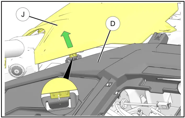
ACCESSORY INSTALLATION
RIGHT-HAND HOOD DISASSEMBLY
TIP
Hood can be disassembled for improved access during installation procedures.
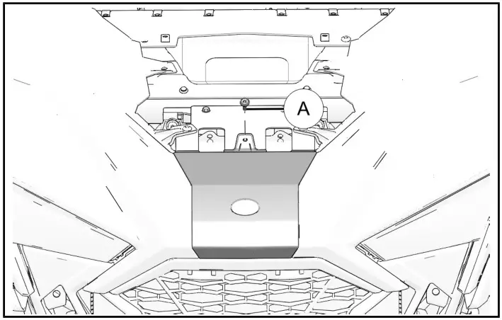
- Remove and retain one fastener A to remove hood nose.

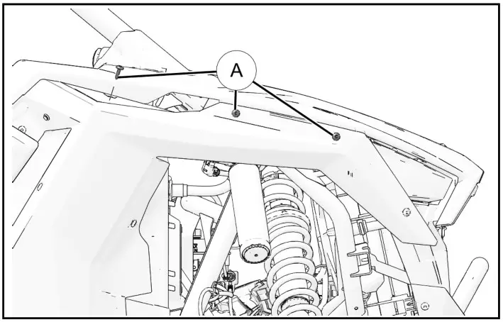
- Remove and retain three front fender fasteners A.

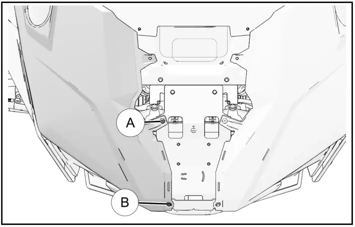
- Remove and retain one hood fastener A and one push-pin rivet B.
ANTENNA INSTALLATION
HOOD PANEL PREPARATION
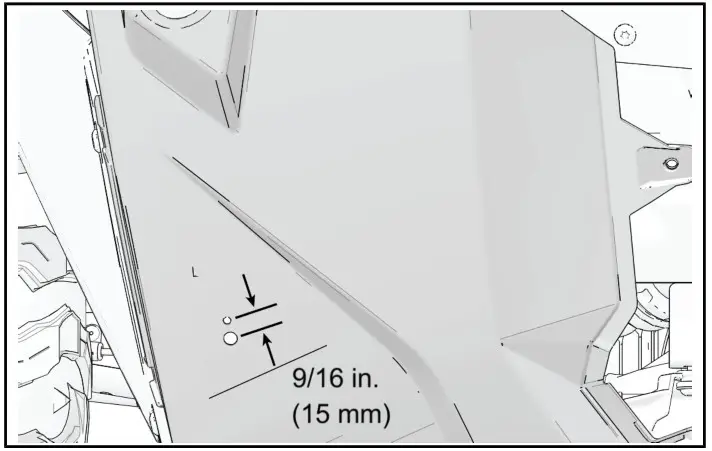
- Mark two holes on top of right front fender for alignment pin and antenna mounting post.
NOTE
Exact location is not critical, however, ensure location allows ground strap to span distance of antenna base to chassis ground location (see step 4 of Antenna Installation section for ground strap location). If mast tilt functionality is desired, ensure location allows for tilt.
MEASUREMENT
Antenna Mounting Post hole: 1/2 in. (12 mm)
Alignment Pin hole: 3/16 in. (5 mm)
Ensure distance between center of each hole is 9/16 in. (15 mm), as shown in diagram below.
- Drill at each marked location.
CAUTION
Control drill depth to prevent damage to underlying structure or components.
MEASUREMENT
Antenna Mounting Post hole: 1/2 in. (12 mm)
Alignment Pin hole: 3/16 in. (5 mm)
Ensure distance between center of each hole is 9/16 in. (15 mm), as shown in diagram below.
Instr 9929592
Rev 01 2019-01


