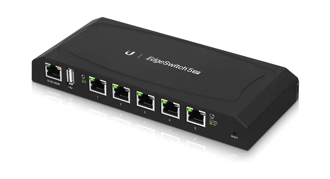
ES-5XP Quick Start Guide
Package Contents

Installation Requirements
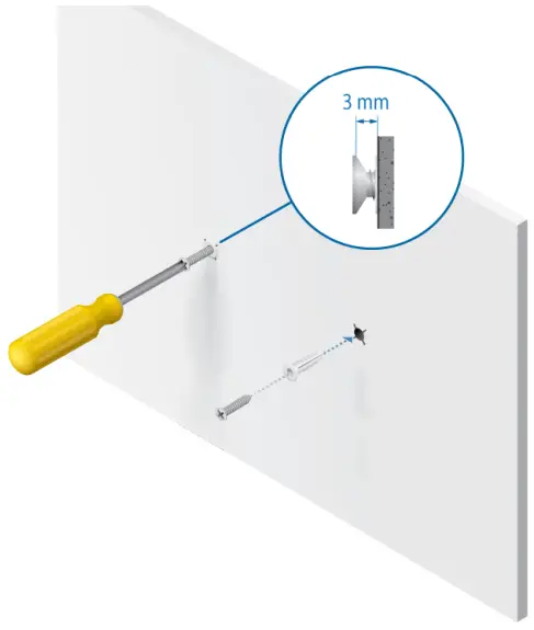
- Drill, 6 mm drill bit, and Phillips screwdriver (wall-mounting)
- For outdoor applications, shielded Category 5 (or above) cabling should be used for all wired Ethernet connections and should be grounded through the AC ground of the power supply.
We recommend that you protect your networks from harmful outdoor environments and destructive ESD events with industrial-grade, shielded Ethernet cable from Ubiquiti. For more details, visit ui.com/toughcable
 IMPORTANT: Although the cabling can be located outdoors, the EdgeSwitch itself should be housed inside a protective enclosure. WARNING: To reduce the risk of re or electric shock, do not expose this EdgeSwitch to rain or moisture.
Hardware Overview
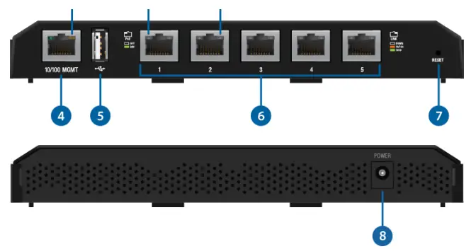
| Management Power/Link LED | |
| Off | No Power/No Link |
| Amber | After bootup, the LED indicates power. After an initial link is established, the LED indicates a 10/100 Mbps connection. If the link terminates, the LED turns off until a link is re-established. If the unit reboots, the LED will again indicate power until a link is established. |
| RJ45 PoE LED (Ports 1 – 5) | |
| Off | No Power over Ethernet |
| Green | 24V Power over Ethernet |
| RJ45 Speed/Link/Act LED (Ports 1 – 5) | |
| Off | No link |
| Amber | Link established at 10/100 Mbps |
| Amber Flashing | Link activity at 10/100 Mbps |
| Green | Link established at 1000 Mbps |
| Green Flashing | Link activity at 1000 Mbps |
| Management Port |
| 10/100 Mbps port used to access the EdgeSwitch Configuration Interface. |
| USB Port |
| Reserved for future use. |
| RJ45 (Ports 1 – 5) |
| Reset Button |
| To reset to factory defaults, press and hold the Reset button for more than 10 seconds while the unit is powered on. |
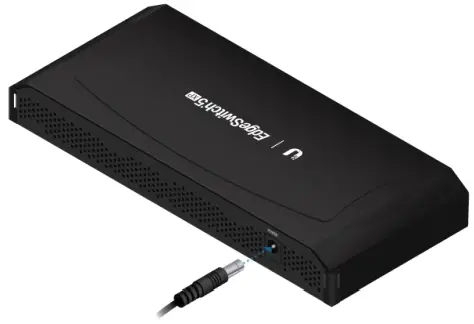
| Power |
| Connect the included Power Adapter to the Power port. |
Hardware Installation
Place the EdgeSwitch on a benchtop or other surface. WARNING: FAILURE TO PROVIDE PROPER VENTILATION MAY CAUSE FIRE HAZARDS.
KEEP AT LEAST 20 MM OF CLEARANCE NEXT TO THE VENTILATION HOLES FOR ADEQUATE AIRFLOW.
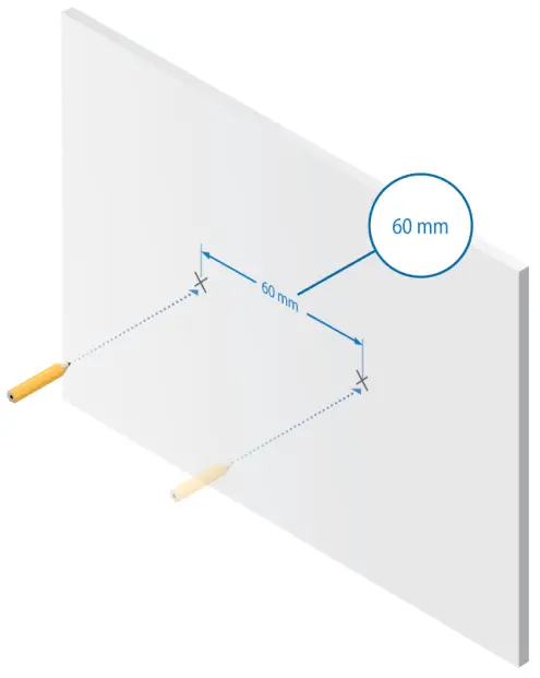
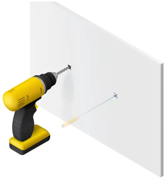
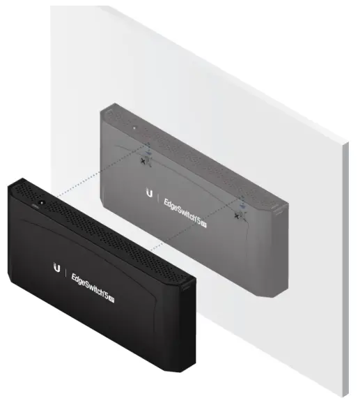
Wall-Mounting
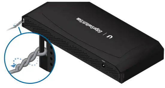
Grounding the EdgeSwitch (Optional)
The EdgeSwitch is grounded through the Power Adapter; however, you can add optional ESD grounding for enhanced ESD protection.
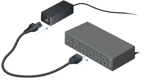
Connecting Power
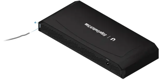
Connecting Ethernet
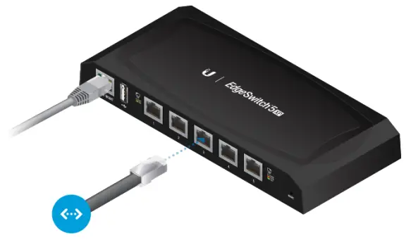
 Note: PoE is disabled by default on all numbered ports and is not available on the Management port. To enable PoE on the appropriate ports, use the Ports tab in the Configuration Interface.
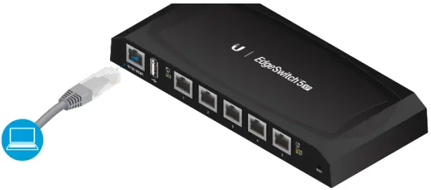
Accessing the Conguration Interface
Connect to the Conguration Interface:
- Ensure that your computer (or another host machine) is connected to the Management port on the EdgeSwitch.
 Note: By default, you can configure the EdgeSwitch via any port; however, we recommend the Management port. (Access to the Conguration Interface can be limited to the Management port only. You can configure this setting on the Device tab.)
 - Configure the Ethernet adapter on your host system with a static IP address on 192.168.1.x subnet (e.g., 192.168.1.100).
- Launch your web browser. Type https://192.168.1.20 in the address eld. Press enter (PC) or Return (Mac).

- Enter ubnt in the Username and Password fields. Click Login.


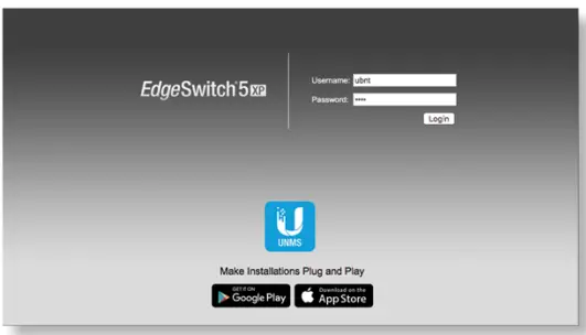
The Conguration Interface will appear and allow you to customize your settings. You can enable PoE on the Ports tab.
You can also manage your device using the Ubiquiti® Network Management System. UNMS™ lets you conjure, monitor, upgrade, and back up your devices using a single application.
Specifications
| ES 5XP | |
| Dimensions | 197 x 87.5 x 27.3 mm (7.76 x 7.28 x 1.61″) |
| Weight | 250 g (8.82 oz) |
| Power Input | 24VDC, 2.5A Power Adapter (Included) |
| Max. Power Consumption | 60W |
| PoE Out Voltage Range | 22-24VDC |
| Max. PoE Wattage Per Data Port | 11.5W |
| ESD Rating | ±24 kV Air/Contact |
| PoE Method | Passive |
| Button | Reset |
| USB Port | 2.0 Type-A (Reserved for Future Use) |
| Processor | MIPS 24K, 400 MHz |
| System Memory | 64 MB |
| Code Storage | 8 MB |
| PoE Configurable Per Port Management Port | N/A |
| LEDs Per Port Management Port Data Ports | Power/Link PoE, Speed/Link/Activity |
| Networking Interfaces Management Port Data Ports | (1) 10/100 Ethernet Port (5) 10/100/1000 Ethernet Ports |
| Operating Temperature | -25 to 55° C (-13 to 131° F) |
| Operating Humidity | 90% Noncondensing |
| Certifications | CE, FCC, IC |
Safety Notices
- Read, follow and keep these instructions.
- Heed all warnings.
- Only use attachments/accessories specified by the manufacturer.
![]() WARNING: Failure to provide proper ventilation may cause re hazard. Keep at least 20 mm of clearance next to the ventilation holes for the adequate arrow.
WARNING: Failure to provide proper ventilation may cause re hazard. Keep at least 20 mm of clearance next to the ventilation holes for the adequate arrow.![]() WARNING: To reduce the risk of re or electric shock, do not expose this product to rain or moisture.
WARNING: To reduce the risk of re or electric shock, do not expose this product to rain or moisture.![]() WARNING: Do not use this product in a location that can be submerged by water.
WARNING: Do not use this product in a location that can be submerged by water.![]() WARNING: Avoid using this product during an electrical storm. There may be a remote risk of electric shock from lightning.
WARNING: Avoid using this product during an electrical storm. There may be a remote risk of electric shock from lightning.
Electrical Safety Information
- Compliance is required with respect to voltage, frequency, and current requirements indicated on the manufacturer’s label. Connection to a different power source than those specified may result in improper operation, damage to the equipment, or pose is a hazard if the limitations are not followed.
- There are no operator serviceable parts inside this equipment. Service should be provided only by a qualied service technician.
- This equipment is provided with a detachable power cord which has an integral safety ground wire intended for connection to a grounded safety outlet.
a. Do not substitute the power cord with one that is not the provided approved type. Never use an adapter plug to connect to a 2-wire outlet as this will defeat the continuity of the grounding wire.
b. The equipment requires the use of the ground wire as a part of the safety certification, modification or misuse can provide a shock hazard that can result in serious injury or death.
c. Contact a qualied electrician or the manufacturer if there are questions about the installation prior to connecting the equipment.
d. Protective earthing is provided by a Listed AC adapter. Building installation shall provide appropriate short-circuit backup protection.
e. Protective bonding must be installed in accordance with local national wiring rules and regulations.
ui.com/support/warranty
The limited warranty requires the use of arbitration to resolve disputes on an individual basis, and, where applicable, specify arbitration instead of jury trials or class actions.
Compliance
FCC
Changes or modifications not expressly approved by the party responsible for compliance could void the user’s authority to operate the equipment.
This device complies with Part 15 of the FCC Rules. Operation is subject to the following two conditions.
- This device may not cause harmful interference, and
- This device must accept any interference received, including interference that may cause undesired operation.
This equipment has been tested and found to comply with the limits for a Class A digital device, pursuant to Part 15 of the FCC Rules. These limits are designed to provide reasonable protection against harmful interference when the equipment is operated in a commercial environment. This equipment generates, uses, and can radiate radio frequency energy and, if not installed and used in accordance with the
instruction manual, may cause harmful interference to radio communications. Operations of this equipment in a residential area is likely to cause harmful interference in which case the user will be required to correct the interference at his own expense.
ISED Canada
CAN ICES-3(A)/NMB-3(A)
Australia and New Zealand
 Warning: This equipment is compliant with Class A of CISPR 32. In a residential environment, this equipment may cause radio interference.
CE Marking
CE marking on this product represents the product is in compliance with all directives that are applicable to it.
![]()
WEEE Compliance Statement
Declaration of Conformity
Online Resources

© 2020 Ubiquiti Inc. All rights reserved.


