WEL-200 Wireless Edge Link
Product Information
WEL-200TM Wireless Edge Link TM
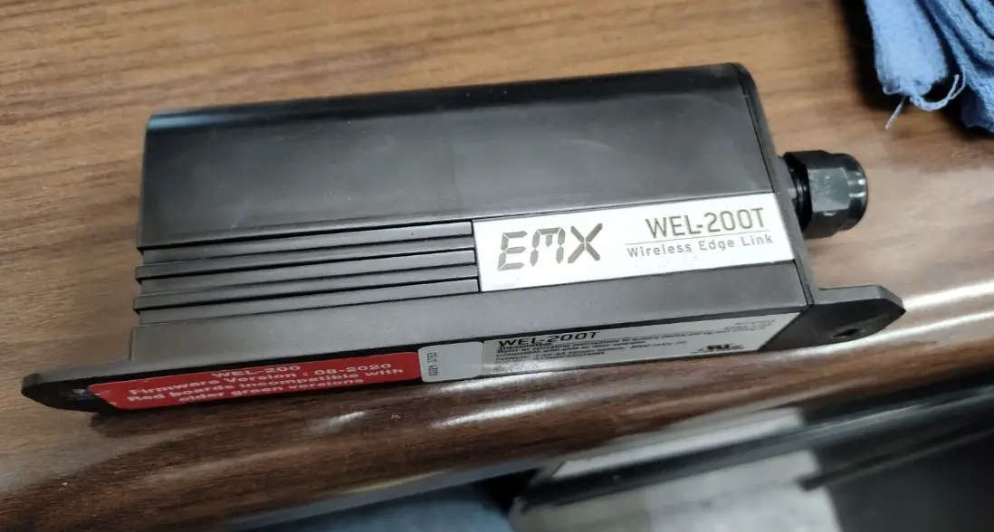
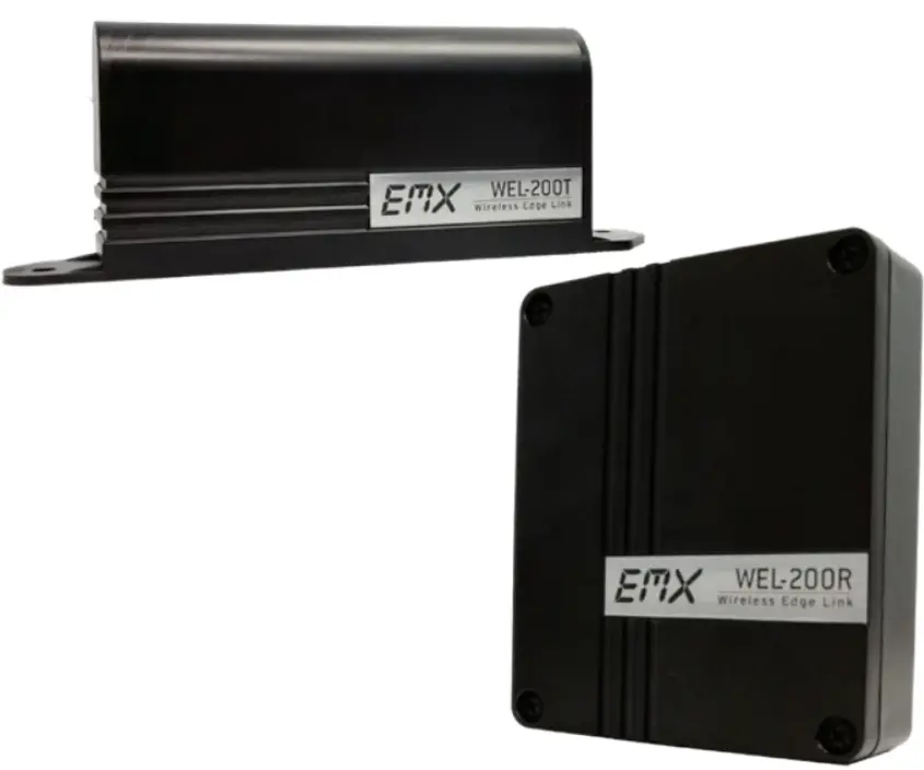
The WEL-200TM is a wireless edge link kit that includes a receiver (WEL-200R) and a transmitter (WEL-200T). It operates at a frequency of 915 MHz with an operating range of 200 ft in line of sight. The response time is 100 ms and it can be used at temperatures ranging from -40°F to 185°F. The power current draw is 12-24 VDC/AC and it comes with surge protection. The transmitter uses 2 AA lithium batteries with a life of approximately 2 years. The WEL-200R has 12 terminals and the WEL-200T has 2 terminals. The WEL-200TM can be used for edge resistance range and has dimensions of 5.5 x 1.3 x 3.5 inches for the receiver and 7 x 1.3 x 2.6 inches for the transmitter.
Ordering Information
- WEL-200K Wireless edge link kit, includes WEL-200R, WEL-200T, 2 cable grip inserts and 2 AA lithium batteries
- WEL-200R Wireless edge link receiver
- WEL-200T Wireless edge link transmitter
Receiver Connections
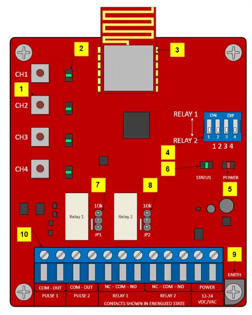
The receiver has channel assignment buttons, channel LEDs, radio, DIP switch, power LED, system status LED, Relay 1 10K jumper, Relay 2 10K jumper, earth ground, and terminal block. It has various terminal descriptions such as pulse output, relay connections, power input, and earth ground connection.
Product Usage Instructions
Connecting the Receiver
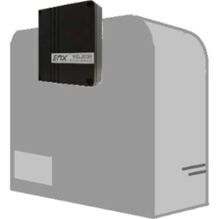
- Mount the receiver to the exterior of the operator using four #8 machine screws, washers, lock washers and nuts.
- Open the cover to expose the mounting holes.
- Place the receiver in direct line of sight with all edge transmitters.
- Mount the receiver with the sealing nut facing down to prevent water from entering the housing.
- Extend the top of the receiver approximately 1 inch above the top edge of the operator housing, or on the side that is in line of sight of all transmitters.
Receiver Connections
The receiver has various terminal blocks for pulse output, relay connections, power input, and earth ground connection. Connect these terminals according to their respective descriptions provided in the user manual.
Transmitter Usage
The WEL-200T transmitter can be used for edge resistance range. It has two terminals which should be connected according to the system requirements. The transmitter uses 2 AA lithium batteries with a life of approximately 2 years. Ensure that the batteries are installed correctly.
DIP Switch Settings
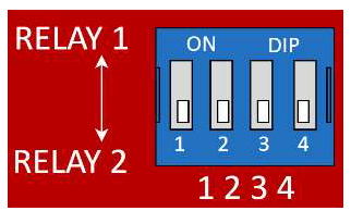
The DIP switch on the receiver assigns each channel to Relay 1 or Relay 2. Check the user manual for more information on how to set this up.
Channel LEDs
The channel LEDs on the receiver indicate various statuses such as when a paired transmitter has a good edge sensor, when a paired transmitter has a shorted edge sensor, when no transmitter is paired to the channel, when a paired transmitter is no longer communicating, and when a connected transmitter has an open edge sensor. Check the user manual for more information on interpreting the channel LEDs.
Tech Support
If you encounter any issues with the product, please contact EMX Industries, Inc. tech support at 216-518-9889 or email at [email protected] for assistance.
Instruction
(For red circuit boards)
The WEL-200 is a complete wireless solution for interfacing sensing edges to gate and door operators, while ensuring compliance with UL325 monitoring standards. The WEL-200 Transmitter (per page 4, step 6) requires the edge (sold separately) to have a built-in resistor with a value between 4K – 12K ohms. Non-resistive edges DO NOT work with this system. Each receiver can connect with up to four transmitters with separate relay and pulse outputs for open and close edge functionality. Each transmitter can run for up to two years on two AA lithium batteries. With enhanced diagnostic features, installation and maintenance for the WEL-200 is easy and reliable. Feedback is provided for all fault modes, including edge open, short conditions, low battery and failed transmitters.
Specifications
| Receiver (WEL-200R) | Transmitter (WEL-200T) | |
| Operating Range | 200 ft (line of sight) | |
| Operating Frequency | 915 MHz (25 possible channels) | |
| Response Time | 100 ms | |
| Operating Temperature | -40° to 140°F (-40 to 60°C) | |
| Power | 12-24 VDC/AC | 2 AA lithium batteries ~ 2 year life |
| Current Draw | 1 Relay – 42mA, 2 Relay – 70mA | N/A |
| Surge Protection | Thermal fuse, MOV | Thermal fuse |
| Outputs | 300 Hz pulsed, or relay with selectable 10K ohm resistor across normally open contact | N/A |
| Edge Resistance Range | – | 4K – 12K Ohms |
| Dimensions | 5.5” (140 mm) x 1.3” (34 mm) x 3.5” (90 mm) | 7” (180 mm) x 1.3” (32 mm) x 2.6” (67 mm) |
| Connections | 12 terminals | 2 terminals |
Ordering Information
- WEL-200K: Wireless edge link kit, includes WEL-200R, WEL-200T, 2 cable grip inserts and 2 AA lithium batteries
- WEL-200R: Wireless edge link receiver
- WEL-200T: Wireless edge link transmitter
Receiver Connections
- Channel assignment buttons
- Channel LEDs
- Off when a paired transmitter has a good edge sensor
- On when a paired transmitter has a shorted edge sensor
- Flashes in sync with system LED when no transmitter is paired to the channel
- Flashes 2x faster than the system LED when a paired transmitter is no longer communicating
- Flashes twice quickly with one second off when a connected transmitter has an open edge sensor.
- Radio
- DIP switch
- Assigns each channel to Relay 1 or Relay 2
- Power LED
- System Status LED
- Slow flash during normal operation
- Fast flash during pair or factory reset
- Relay 1 10K Jumper
- Relay 2 10K Jumper
- Earth ground
| Terminal | Description |
| PULSE 1 COM | Pulse common connection for channels assigned to Relay 1 on DIP switch |
| PULSE 1 OUT | Pulse output for channels assigned to Relay 1 (300/0 Hz) |
| PULSE 2 COM | Pulse common connection for channels assigned to Relay 2 on DIP switch |
| PULSE 2 OUT | Pulse output for channels assigned to Relay 2 (300/0 Hz) |
| RELAY 1 NC | Normally closed relay connection for channel assigned to Relay 1 on DIP switch |
| RELAY 1 COM | Common relay connection for channels assigned to Relay 1 |
| RELAY 1 NO | Normally open relay connection for channels assigned to Relay 1 |
| RELAY 2 NC | Normally closed relay connection for channel assigned to Relay 2 on DIP switch |
| RELAY 2 COM | Common relay connection for channels assigned to Relay 2 |
| RELAY 2 NO | Normally open relay connection for channels assigned to Relay 2 |
| POWER | 12-24 VDC/AC power input (non-polarized) |
| EARTH | Earth ground connection (not required) |
Installation
Connecting the Receiver
- Mount the receiver to the exterior of the operator using four #8 machine screws,
 TIP: Extend the top of the receiver approximately 1” above the top edge of the operator housing, or on the side that is in line of sight of all transmitters.
 - Pass the operator wires through the sealing nut, cable grip, and body into the receiver housing.
 TIP:
TIP:- Cables for the original cable grip insert must be 0.181-0.321” (4.6-7.9 mm) in diameter to maintain a proper watertight seal.
- For smaller cables, replace the original cable grip insert with a white insert by removing it from inside the body.
- To maintain a watertight seal, 1.) only use round cables 2.) mount the receiver with the sealing nut facing down
- Connect the operator wires to the terminal block, per one of the monitoring methods below and according to the instructions provided by the operator manufacturer. Connect power wires last.
 Pulse Monitoring
- For channels assigned to Relay 1, connect the operator common to terminal 1 and operator input to terminal 2.
- For channels assigned to Relay 2, connect the operator common to terminal 3 and operator input to terminal 4.
10K or Normally Closed Monitoring - For channels assigned to Relay 1, connect the operator common to terminal 6, and the operator input to terminal 5 or 7.
- For channels assigned Relay 2, connect the operator common to terminal 9, and the operator input to terminal 8 or 10.
- For 10K resistive monitoring, place the jumper on the receiver in the 10K position (bottom two pins) as shown. This places a 10K resistance across the NO relay contacts.
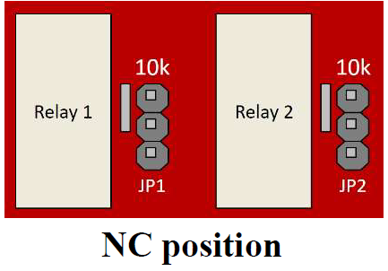
- For NC, move the jumper on the receiver to the top two pins.


- On the DIP switch, indicate which channels will output through Relay 1 and Relay 2 terminals. The DIP switch in the image shows all four channels outputting through Relay 2 terminals.

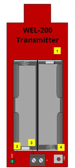
- Mount the transmitter near the edge sensor using two #8 machine screws, washers, lock washer and nuts. Pass the edge sensor wires through the sealing nut as in step 2. Mount the transmitter with the sealing nut facing down to prevent water from entering the housing.
- Connect the resistor equipped edge sensor wires to the transmitter terminal block (#3 on image). Insert batteries. The LED (#2 on image) will quickly flash 2x every two seconds.
TIP:- Never connect more than one edge sensor to a single transmitter.
- The edge sensor must have a resistance between 4K – 12K ohms.
- A channel LED flashing three times per second indicates that the batteries are low (less than 2.7 V) and need to be replaced.

- After powering the receiver, the system status LED will flash rapidly while it is finding a clean operating frequency (this can last several seconds). Once completed, the system status LED will flash on/off every 2 seconds. Initialization is now complete.
TIP: To perform a factory reset of the receiver, press 1 and 4 channel assignment buttons simultaneously until the status LED flashes quickly. This will clear all connected channels and reset the system. - To enter channel assignment mode, on the receiver, hold down the desired channel assignment button until the systems status LED begins flashing rapidly, then release the button.
To exit channel assignment mode, wait 120 seconds or cycle power to the receiver. - On the transmitter, press and hold down the connection button (#4 on image above) for 1 – 2 seconds until its LED stops flashing rapidly. Upon successful connection, the LED flashes once every four seconds. If the transmitter fails to connect, it will return to its initial state, with the LED flashing twice fast every two seconds. If this occurs, repeat this step. If the transmitter continues to fail to connect, proceed to the troubleshooting section.
TIP: To remove a connection from the transmitter, hold down the connection button. The LED will turn on solid for several seconds, and then flash twice every two seconds when disconnected. - Test the connection. Without activating the edge sensor, observe the channel LEDs on the receiver. They should be off for any channel connected to a transmitter. Activate the edge sensor being tested. On the receiver, the channel LED for the tested edge’s channel should turn on. On the transmitter, the LED should flash twice every second while the edge sensor is activated. If the channel does not exhibit this behavior, double check the edge sensor wiring, termination, and transmitter batteries.
- Repeat steps 5 through 10 for each additional transmitter. Never connect more than one edge sensor to a single transmitter.
 TIP: Extend the top of the receiver approximately 1” above the top edge of the operator housing, or on the side that is in line of sight of all transmitters.
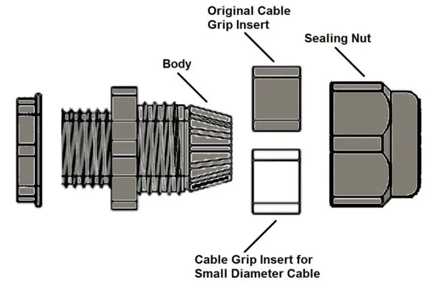 TIP:
TIP: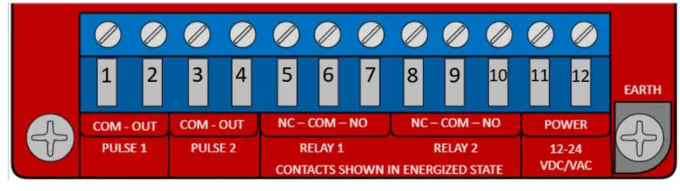 Pulse Monitoring
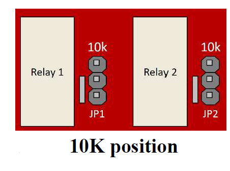
WEL-200 Compatibility (Red Board and Green Boards)
- New WEL-200 systems (Red Boards) will not be compatible with older receivers and transmitters (Green Boards). This is because of an upgrade to the communication protocol as well as other advancements in the system’s ability to find clean RF channels.
- Using the color of the boards is the best way to determine compatibility.
- Transmitters with a GREEN PCB must be used with a receiver that also has a GREEN PCB.
- Transmitters with a RED PCB must be used with a receiver that also has a RED PCB.
Troubleshooting
| Symptom | Possible cause | Solution |
| Receiver channel LED is on, regardless of edge sensor state | Edge sensor’s resistance is too low Edge wires are shorted |
|
| 3. If the meter reads outside of this range the edge sensor is defective. Replace the edge sensor. | ||
| Receiver channel LED flashes 2x then pauses every second | Edge sensor resistance above 12K Improper connection to edge sensor Damaged wires |
|
| 3. Press on the edge sensor and confirm resistance drops to zero. | ||
| Receiver channel LED flashes once per second | Transmitter not connected to receiver | Repeat step 9 in transmitter installation |
| Receiver channel LED flashes 0.5 seconds on, 0.5 seconds off | Poor signal Strength | Ensure Receiver and Transmitter have line of sight throughout gate open/close operation. |
| Completely dead batteries | If new AA lithium batteries are installed in transmitter and the transmitter LED does not light, then replace transmitter. | |
| Receiver channel | Transmitter batteries are | Replace batteries with two AA lithium batteries |
| LED flashes 3x per | low (less than 2.7V) | 1.5V |
| second or | ||
| transmitter LED | ||
| flashes 6x quickly. |
Warranty
EMX Industries, Inc. products have a warranty against defects in materials and workmanship for a period of two years from date of sale to our customer.
EMX Industries, Inc.
Document No. 10320104 Rev 3.0
Tech support: 216-518-9889 [email protected]


