![]() Item No: 41103,41104, 41503, 41504, 41603, 41604
Item No: 41103,41104, 41503, 41504, 41603, 41604
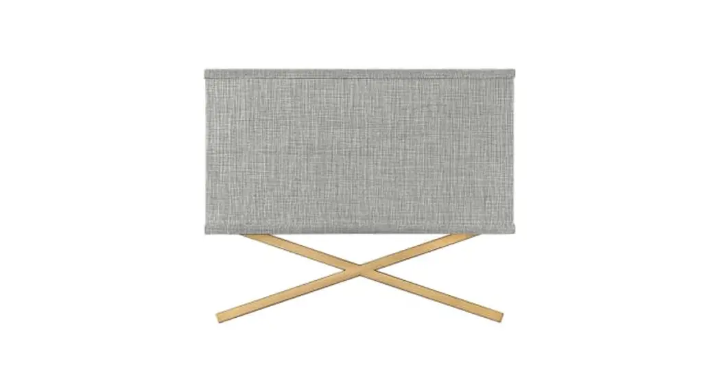
Series Wall Sconce
Installation Guide
41103 Series Wall Sconce
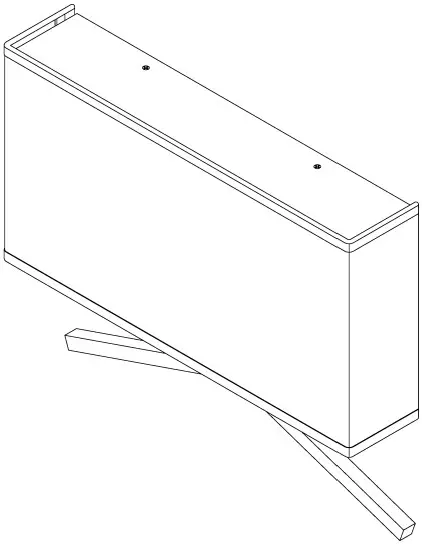
DRAWING 1 – ASSEMBLY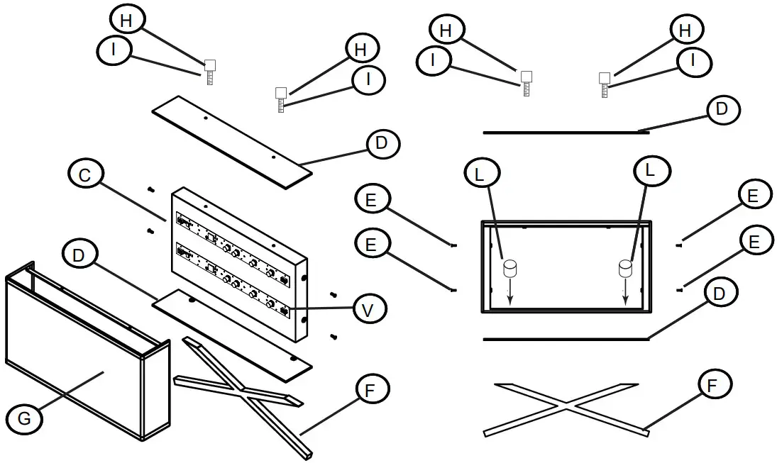
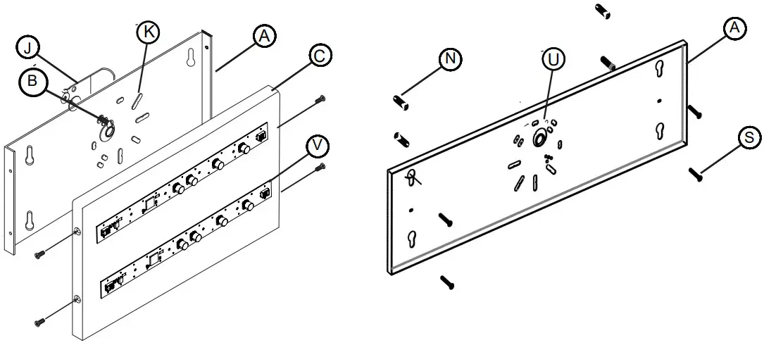
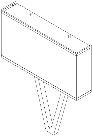
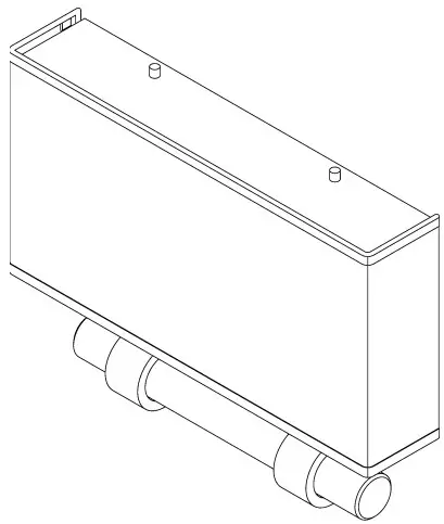
| DRAWING 2- JUNCTION BOX MOUNTING | DRAWING 3- NON-JUNCTION BOX MOUNTING |
 | |
Assembly Instructions
![]() start here
start here
For junction box mounting:
- To begin remove mounting plate (A) from backplate(C) by removing the four screws (E) located on the side of fixture see drawing 2.
- Next determine which knockouts (K) need to be removed in order to secure mounting plate (A) to the junction box (J)
- Use two 8-32 screws (not provided) (B) to secure mounting plate (A) to junction box (J)
- Next assemble finial at bottom of fixture secure lock ups (L) on top of diffuser (D) and finial (F).
- Connect black live wire (W) on fixture to supply wire inside junction box (X) using wire nuts provided
- Connect white neutral wire (Z) on fixture to neutral wire inside junction box (Y) using wire nuts provided.
- To ground fixture fasten ground wire to ground screw inside mounting plate
- Attach backplate (C) to mounting plate using the four screws provided
- Line up holes from backplate(C), shade (G), and diffuser (D).
- Next screw in ball knobs (H) in those holes so that the backplate, shade and diffuser are all assembled
DRAWING 4 – WIRING 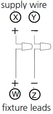
REPLACEMENT PARTS
 41103
41103
| Part Letter | Part number | Description | CITY |
| V | EL2G16W7W1 | 12″ LINEAR 16W LED BOARD | 2 |
| G | SH003SLB | LONG OFF WHITE SLUB SHADE | 1 |
| F | TC4122XX | WIDE STEMS IN XX | 1 |
| D | R41103DIF | LARGE AXIS SCONCE BOTTOM DIFFUSER | 1 |
| D | R4003DIF | LARGE 2 HOLE TOP DIFFUSER | 1 |
| H | K4001XX | TOP BARREL KNOB 8MMX8MM | 2 |
| I | P4001STUD | THREDED STUD M” | 2 |
| L | K4003XX | BARREL KNOB 10MMx1OMM | 2 |
41104
| Part Letter | Part number | Description | QTY |
| V | EL2G16W7W1 | 12″ LINEAR 16W LED BOARD | 2 |
| G | SHOO4SLIN | LONG LINEN SHADE | 1 |
| F | TC4122XX | WIDE STEMS IN XX | 1 |
| D | R41103DIF | LARGE AXIS SCONCE BOTTOM DIFFUSER | 1 |
| D | R4003DIF | LARGE 2 HOLE TOP DIFFUSER | 1 |
| H | K4001XX | TOP BARREL KNOB 8MMX8MM | 2 |
| I | P4001STUD | THREDED STUD 1/2″ | 2 |
| L | K4003XX | BARREL KNOB 10MMx1OMM | 2 |
 41503
41503
| Part Letter | Part number | Description | QTY |
| V | EL2G16W7W1 | 12″ LINEAR 16W LED BOARD | 2 |
| G | SH003SLB | LONG OFF WHITE SLUB SHADE | 1 |
| F | TC41S2XX | WIDE STEMS IN XX | 1 |
| D | R41103DIF | LARGE AXIS SCONCE BOTTOM DIFFUSER | 1 |
| D | R4003DIF | LARGE 2 HOLE TOP DIFFUSER | 1 |
| H | K4001XX | TOP BARREL KNOB 8MMX8MM | 2 |
| I | P4001STUD | THREDED STUD 1/2″ | 2 |
| L | K4003XX | BARREL KNOB 10MMx1OMM | 2 |
41504
| Part Letter | Part number | Description | QTY |
| VK | EL2G16W7W1 | 12″ LINEAR 16W LED BOARD | 2 |
| G | SHOO4SLIN | LONG LINEN SHADE | 1 |
| F | TC4122XX | WIDE STEMS IN XX | 1 |
| D | R41103DIF | LARGE AXIS SCONCE BOTTOM DIFFUSER | 1 |
| D | R4003DIF | LARGE 2 HOLE TOP DIFFUSER | 1 |
| H | K4001XX | TOP BARREL KNOB 8MMX8MM | 2 |
| I | P4001STUD | THREDED STUD 1/2″ | 2 |
| L | K4003XX | BARREL KNOB 10MMx10MM | 2 |
 41603
41603
Part Letter | Part number | Description | QTY |
| V | EL2G16W7W1 | 12″ LINEAR 16W LED BOARD | 2 |
| G | SH003SLB | LONG OFF WHITE SLUB SHADE | 1 |
| F | TC4162XX | LONG STEMS IN XX | 1 |
| D | R41103DIF | LARGE AXIS SCONCE BOTTOM DIFFUSER | 1 |
| D | R4003DIF | LARGE 2 HOLE TOP DIFFUSER | 1 |
| H | K4001XX | TOP BARREL KNOB 8MMX8MM | 2 |
| I | P4001STUD | THREDED STUD 1/2″ | 2 |
| L | K4003XX | BARREL KNOB 10MMx1OMM | 2 |
41604
| Part Letter | Part number | Description | QTY | |
| V | EL2G16W7W1 | 12″ LINEAR 16W LED BOARD | 2 | |
| G | SHOO4SLIN | LONG LINEN SHADE | 1 | |
| F | TC4162XX | LONG STEMS IN XX | 1 | |
| D | R41103DIF | LARGE AXIS SCONCE BOTTOM DIFFUSER | 1 | |
| D | R4003DIF | LARGE 2 HOLE TOP DIFFUSER | 1 | |
| H | K4001XX | TOP BARREL KNOB 8MMX8MM | 2 | |
| I | P4001STUD | THREDED STUD 1/2″ | 2 | |
| L | K4003XX | BARREL KNOB 10MMx1OMM | 2 | |
DRAWING 1 – UNMOUNTING FIXTURE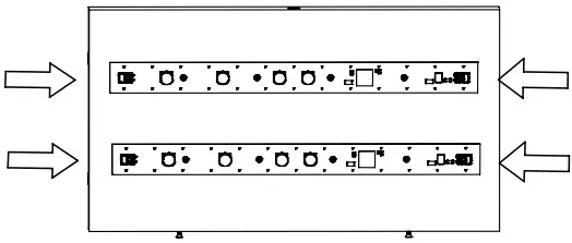 DRAWING 2 – LED REPLACEMENT
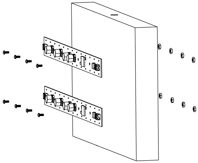 DRAWING 3- WIRING LED
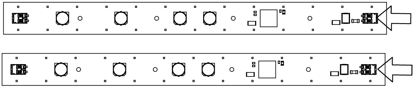
LED replacement Instructions
![]() start here
start here
- To replace LED, first make sure that there is no power to the LED
- To remove fixture from mounted location unscrew the four screws that hold backplate to mounting plate (Refer to drawing 1)
- Disconnect both supply and neutral wires that connect the fixture to junction box or other power supply
- Remove shade and diffusers from fixture so that LED is accessible (Refer to assembly Instructions on page 1)
- Disconnect neutral and supply wires that connect the LED to the fixture . This can be done by pushing down on the push in connectors with a pen or small screwdriver, and simultaneously pulling the wires out. (Refer to drawing 3)
- Remove defected LED by removing the small screws that hold in the LED board to the backplate
- To attach new LED board use hex nuts and screws that were used to attach the previous LED to the backplate.
The gray thermal PAD that rested in-between the LED and backplate can be reused and should be placed between the new LED and backplate.(Refer to drawing 2) - Reconnect wires from the fixture to the new LED. This can be done by pushing down on the push in connectors with a pen or small screwdriver, and simultaneously pushing the wires into the connectors. (Refer to drawing 3)
- Reassemble shade and diffusers onto fixture. (Refer to assembly Instructions on page 1)
- Remount fixture to its original location and restore power. (Refer to drawing 1)
HINKLEY 33000 Pin Oak Parkway, Avon Lake,
OH 44012 800.446.5539 / 440.653.5500
hinkley.com


