BLUE JAY GYDCG-UBC1 Series DC Insulation Monitor User Manual

SUMMARIZE
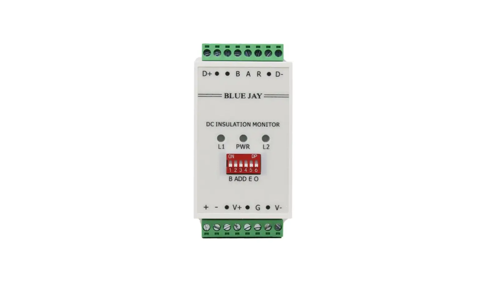
The GYDCG-UBC1 Series model product is an efficient insulation monitoring device designed for car charging piles. It can monitor the insulation condition of the DC power system of the car charging pile in real time, detect and alarm any potential insulation failure in time, so as to effectively prevent the occurrence of fire and safety accidents. Users can realize the start and stop of a certain insulation monitoring and the acquisition of values through RS485 communication.
This product has the characteristics of high reliability, easy installation, and convenient use. It is one of the important equipment to ensure the safe and stable operation of car charging piles. In addition, the monitor can also provide effective information about the charging pile power system through data analysis and processing, and provide an important reference for operation management and maintenance.
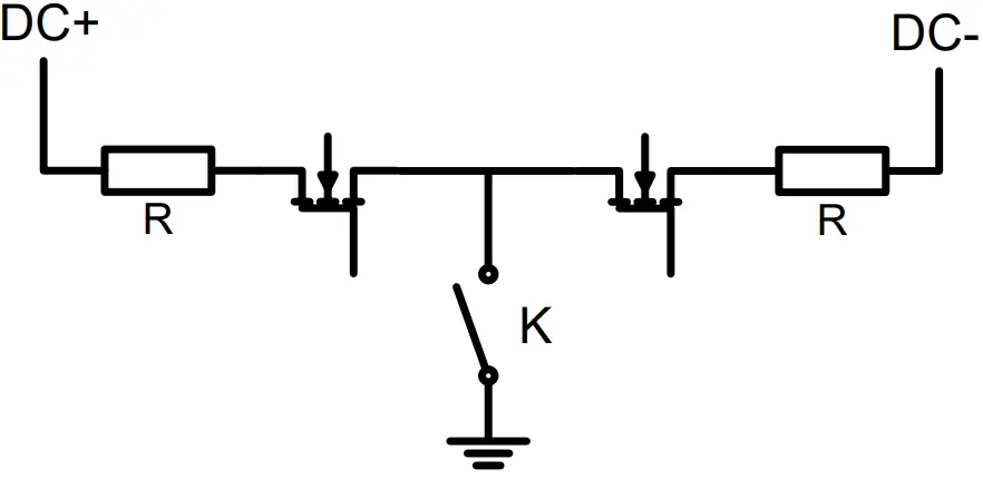
The product can send communication frames through RS485 to turn on or off the insulation
monitoring function. After the insulation monitoring function is turned on, the high-voltage grounding switch K is closed and the real-time measurement of insulation resistance is realized. After the insulation monitoring function is turned off, the high-voltage grounding switch K is disconnected. The host can send read command to read the insulation resistance value of positive and negative poles at any time.
FEATURES
- Remote monitoring and management
- Monitor positive and negative poles
- Ground insulation resistance
- DC voltage monitoring
- Vehicle side DC voltage monitoring
- Voltage reverse polarity alarm
APPLICATIONS
- DC capacitor discharge
- Guarantee the safety and stability of charging
- Improvement of the efficiency and charging quality
- Personnel and equipment security
TECHNICAL PARAMETERS
Basic parameters
| Parameter | Value |
| Power supply | 9~30VDC, power 4w |
| DC voltage range | 0V~1000V |
| Vehicle side voltage measurement range | 0V~1000V |
| Off-line pressure test | <2mA |
| Standard | IEC 61851-23 (2014-03):2014-11 |
| Humidity | 85% |
| Storage temperature | – 40°C ~125°C |
| Operating temperature | – 40°C ~70°C |
| DC voltage at pile side accuracy | ≤2V+0.3% |
| Insulation monitoring accuracy | ≤3KΩ+5% |
| Insulation resistance measurement range | 1KΩ~10 MΩ |
Other parameters
| Pressure point | Maximum voltage rating | Time |
| D+/D- TO GND | 4200VDC/3000VAC | ≤1min |
| Power supply +/- TO GND | 4200VDC/3000VAC | ≤1min |
| RS485 A/B TO GND | 3000VDC/2500VAC | ≤1min |
INSTALLATION
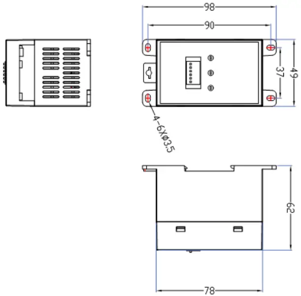
Mounting
The module can be installed by guide rail or screw fixation. Guide rail using standard width 36mm.
External dimensions are shown as follows: (Unit: mm)
Connection Terminal
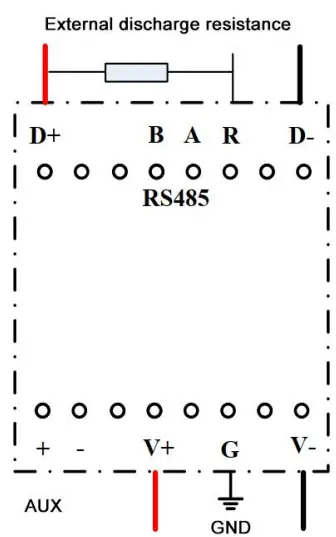
Modules without discharge function need not be connected with external discharge resistance; Without vehicle side measurement, there is no need to connect the DC voltage V+ and V- on the vehicle side.
| Interface | Connection mode | |
| D+ | Positive pole of DC | |
| Upper | D- | Negative pole of DC |
| A | RS485-A | |
| B | RS485-B | |
| + | Positive pole of power supply | |
| – | Negative pole of power supply | |
| Lower | Positive pole of vehicle side voltage | |
| V+ | ||
| V- | Negative pole of vehicle side voltage | |
| GND | Grounding point |
COMMUNICATION INTERFACE
Connection for RS485
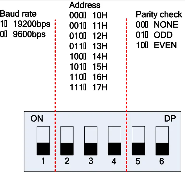
In RS485 communication system, this IMD module works in slave mode. Baud rate, communication address, parity check mode, can be set by DIP switch, default stop bit 1, data bit 8. The interval between each byte in the sent frame must not exceed 20ms, otherwise the frame will be cleared.
Communication Parameter configuration bit
Dip switch 1 bit is used to set the baud rate, 2 to 4 bits are used to set the communication address, and 5,6 bits are used to set the parity check. The setting mode is shown below.
MODBUS © protocol
The GYDCG-UBC1 Series adopts the standard Modbus-RTU protocol and the custom Modbus protocol. The description of two protocols are listed below. Please refer to the protocol description in the corresponding chapter according to the product.
Modbus RTU Frame Format:
| Address code | 1 BYTE | Slave device address 1-247 |
| Function code | 1 BYTE | Indicates the function codes like read coils / inputs |
| Data code | 4 BYTE | Starting address, high byte Starting address, low byte Length of registers, high byte Length of registers, low byte |
| Error Check code | 2 BYTE | Cyclical Redundancy Check ( CRC ) |
MODBUS FUNCTIONS:
| Code | Meaning | Description |
| FUNCTION 03 | Read holding register | This function permits to read all the electrical parameters. |
| FUNCTION 06 | Write single register | This function permits to write a value into a single holding register. |
Register map
| Register | Data | Byte mode | Instruction | |
| 0x0010 | Bus voltage | float | Unit:0.1V,voltage between positive and negative poles of DC bus | |
| 0x0012 | Positive insulation resistance | float | 1 | The unit is KΩ, an integer |
| 0x0013 | Negative insulation resistance | float | 1 | The unit is KΩ, an integer |
| 0x001A | Read version number | float | 1 | |
| 0x001B | IO state | float | 1 | Bit1: Insulation resistance monitoring function is effective.
Bit2: Whether the insulation monitoring is turn on and the ground switch is closed. Bit7: DC bus voltage reverse connection alarm (position 1 when reverse connection voltage is above 170V) |
| 0x0102 | Insulation monitoring and control | float | Enable insulation monitoring function | |
| Insulation monitoring and control | Disable insulation monitoring function | |||
| 0x66 | The host broadcast reads the slave address | float | Example of reply from the slave 0xFF 0x66 0x01 0xAB 0x90 The slave machine address is 0x01 | |
The samples:
| Sample1 | Start insulation monitoring |
| Host inquiry:
01 06 01 02 00 11 E9 FA
Slave response: 01 06 02 00 11 78 84 | |
| Sample2 | Turn off insulation monitoring |
| Host inquiry:
01 06 01 02 00 00 29 F6
Slave response:
01 06 02 00 00 B8 88 | |
| Sample3 | Read the DC bus voltage and positive and negative poles resistance to the ground (read 4 registers) |
| Host inquiry:
01 03 00 10 00 04 45 CC
Slave response:
01 03 08 13 88 02 58 EA 60 02 58 C8 75
Definition: Read the DC voltage 0X1388(500V), the total insulation resistance 0X0258 (600KΩ), the positive insulation resistance 0XEA60 (infinite), the negative insulation resistance 0x0258 (600 KΩ). | |
| Sample4 | Read IO status: |
| Host inquiry:
01 03 00 1B 00 01 F4 0D
Slave response:
01 03 02 00 84 B8 27
Definition: Bus voltage reverse connection, insulation monitoring is started | |
| (ground relay is closed), insulation resistance monitoring is turn off. Slave response:
01 03 02 00 06 38 46
Definition: There is no reverse connection of bus voltage, insulation monitoring is started (ground relay is closed), and insulation resistance monitoring is turn on. | |
| Sample5 | Read version number |
| Host inquiry:
01 03 00 1A 00 01 A5 CD
Slave response:
01 03 02 22 01 61 24
Definition: The version number is V2201. |
Modbus Custom Frame Format:
GYDCG-UBC1 series adopts custom Modbus protocol. Except for sending address command is variable. CRC is obtained according to the actual calculation, register data are defined and unchanged. Described as following:
Write operation function definition: Writes a single register (No slave response)
| Sample1 | Start insulation monitoring |
| Host inquiry:
01 06 01 02 00 11 E9 FA
Slave response: 01 06 02 00 11 78 84 | |
| Sample2 | Turn off insulation monitoring |
| Host inquiry:
01 06 01 02 00 00 29 F6
Slave response:
01 06 02 00 00 B8 88 | |
| Sample3 | Read the DC bus voltage and positive and negative poles resistance to the ground (read 4 registers) |
| Host inquiry:
01 03 00 10 00 04 45 CC
Slave response:
01 03 08 13 88 02 58 EA 60 02 58 C8 75
Definition: Read the DC voltage 0X1388(500V), the total insulation resistance 0X0258 (600KΩ), the positive insulation resistance 0XEA60 (infinite), the negative insulation resistance 0x0258 (600 KΩ). | |
| Sample4 | Read IO status: |
| Host inquiry:
01 03 00 1B 00 01 F4 0D
Slave response:
01 03 02 00 84 B8 27
Definition: Bus voltage reverse connection, insulation monitoring is started | |
| (ground relay is closed), insulation resistance monitoring is turn off. Slave response:
01 03 02 00 06 38 46
Definition: There is no reverse connection of bus voltage, insulation monitoring is started (ground relay is closed), and insulation resistance monitoring is turn on. | |
| Sample5 | Read version number |
| Host inquiry:
01 03 00 1A 00 01 A5 CD
Slave response:
01 03 02 22 01 61 24
Definition: The version number is V2201. | |
| Definition 1 | Enable insulation monitoring function (ground relay is closed) |
| Host inquiry:
Addr. 02 00 02 10 20 CRC CRC | |
| (No slave response) | |
| Definition 2 | Turn off insulation monitoring function (ground relay is disconnected) |
| Host inquiry:
Addr. 02 00 02 10 00 CRC CRC | |
| (No slave response) | |
| Definition 3 | Open discharge (for products with discharge function, the discharge will be automatically closed) |
| Host inquiry: Addr. 02 00 02 10 0C CRC CRC | |
| (No slave response) |
Read data definition
Definition 1 Read DC voltage, positive and negative insulation resistance
- Host inquiry:
- Addr. 01 02 03 04 05 CRC CRC
- Slave response:
- 02(H): Status word height bytes (Correspondence Address)
- 02(L): Status word low bytes
- 03(H): Dc voltage high bytes
- 03(L): Dc voltage low byte
- 04(H): Positive insulation resistance high bytes
- 04(L): Positive insulation resistance low bytes
- 05(H): Negative insulation resistance high bytes
- 05(L): Negative insulation resistance low bytes
- CRC: According to actual calculation
- CRC: According to actual calculation
Command example:
Host inquiry:
10 01 02 03 04 05 0C 30
Slave response:
10 30 01 F4 EA 60 00 32 74 D3
Definitions:
- 02H: Data=0X1030, indicate: the mailing address is 10H;
- Bit4 =1 indicates that the module is working and can be queried.
- 03H: Data=0X01F4=500, indicate: the DC voltage is 500V.
- 04H: Data=0XEA60=60000, indicate: the positive insulation resistance is infinite.
- 05H: Data=0X0032=50, indicate: the negative insulation resistance value 50KΩ
Definition 2 Read vehicle side voltage
- Host inquiry:
- Addr.01 02 FF 08 09 CRC CRC
- Slave response:
- 02(H): Status word height bytes (Correspondence Address)
- 02(L): Status word low bytes
- 00(H): FF
- 00(L): FF
- 08(H): Vehicle side voltage high byte
- 08(L): Pile side voltage high byte
- 09(H): 00
- 09(L): 00
- CRC: According to actual calculation
- CRC: According to actual calculation
Command example:
Host inquiry:
10 01 02 FF 08 09 C9 05
Slave response:
10 30 FF FF 01 90 00 00 70 CE
Definitions:
02H: Data=0X1030, indicate: the mailing address is 10H;
Bit4 =1 indicates that the insulation monitoring of the module is complete and can be read.
08H Data=0X0190=400, indication: the DC voltage on the side of the vehicle is 400V.
02H Indicates the meaning of the status word
| Bit0 | Vehicle side DC voltage reverse connection fault detection (reverse voltage above 30V)
0= no reverse connection; 1 = reverse connection |
| Bit1 | Pile side DC voltage reverse connection fault detection (reverse voltage above 180V)
0= no reverse connection; 1 = reverse connection |
| Bit2 | NC |
| Bit3 | NC |
| Bit4 | Insulation monitoring result status query 0= insulation monitoring resistance value is invalid, and the insulation resistance value read at this time is meaningless; 1= The insulation monitoring resistance value is effective and can be read |
| Bit5 | Insulation monitoring grounding relay status query 0= The ground switch is disconnected; insulation monitoring does not work; 1= Ground switch closed, insulation monitoring is working. |
| Bit6 | NC |
| Bit7 | NC |
| Bit8~ Bit15 | Correspondence address |
MODEL SELECTION SHEET
| DC Insulation Monitor (Small Model, Single Channel) | |
| GYDCG-UBC1 | Single-circuit insulation monitoring DC voltage detection |
| GYDCG-UBC1SMV | Single-circuit insulation monitoring DC voltage detection vehicle side voltage measurement |
| GYDCG-UBC1X | Single-circuit insulation monitoring DC voltage detection DC capacitor discharge |
| GYDCG-UBC1MVX | Single-circuit insulation monitoring DC voltage detection vehicle side voltage measurement DC capacitor discharge |
SAFETY CONSIDERATIONS
![]() All installation specification described at the previous chapters named: INSTALLATION AND STARTUP, INSTALLATION MODES and SPECIFICATIONS.
All installation specification described at the previous chapters named: INSTALLATION AND STARTUP, INSTALLATION MODES and SPECIFICATIONS.
Please note that with the instrument powered on, the terminals could be dangerous to touching and cover opening actions or elements removal may allow accessing dangerous parts. This instrument is factory-shipped at proper operation condition.
- The device must have a professional installation and maintenance
- Any operation of the device, you must cut off the input signal and power;
MAINTENANCE
The GYDCG-UBC1 Series does not require any special maintenance. No adjustment, maintenance or repairing action should be done when the instrument is open and powered on, should those actions are essential, high-qualified operators must perform them.
Before any adjustment, replacement, maintenance or repairing operation is carried out, the instrument must be disconnected from any power supply source.
When any protection failure is suspected to exist, the instrument must be immediately put out of service. The instrument’s design allows a quick replacement in case of any failure.
Question 1: The power indicator LED is off
Check whether the power supply terminal of the module is improperly connected, or the hot swap overcurrent causes the fuse to burn, try to avoid hot plug.
Question 2:The insulation monitoring resistance is infinite after the simulation of insulation resistance
Check whether the ground cable is connected reliably at GND port.
Question 3: The insulation monitoring resistance is much smaller than actual value
The DC ground capacitance may be too large. Check the DC ground capacitance
For any inquiry about the instrument performance or any failure,
contact to Blue Jay’s technical service.
Blue Jay – After-sales service
E-mail: [email protected]


