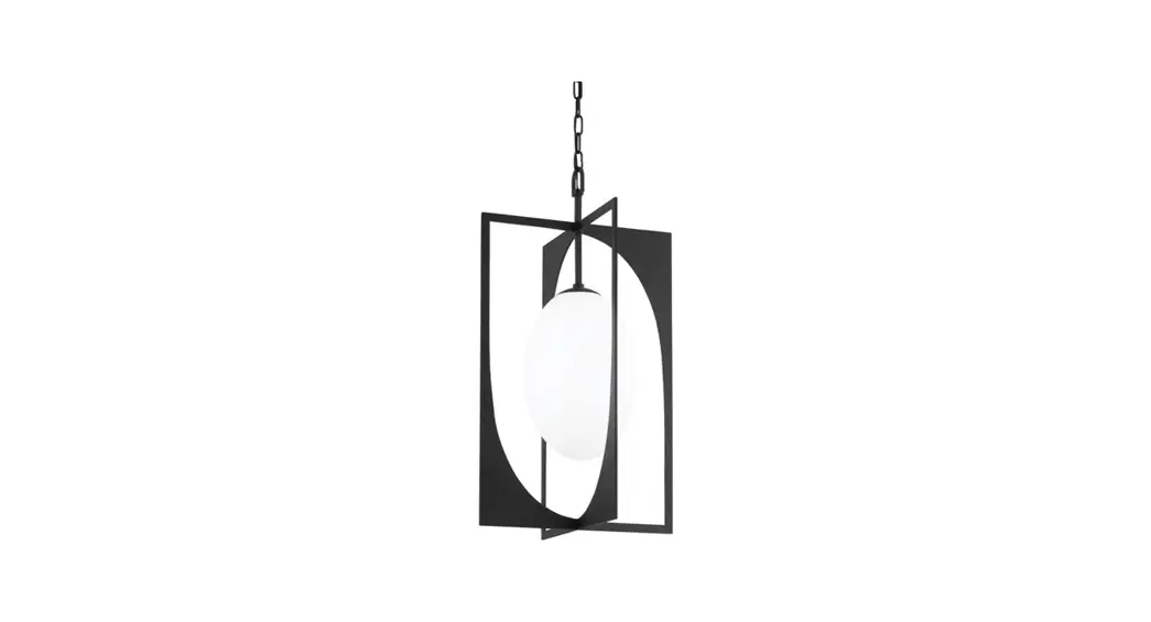
![]() F1218 1 Light 10-inch Gesso White Pendant Ceiling Light
F1218 1 Light 10-inch Gesso White Pendant Ceiling Light
Instruction Manual
F1218 1 Light 10-inch Gesso White Pendant Ceiling Light
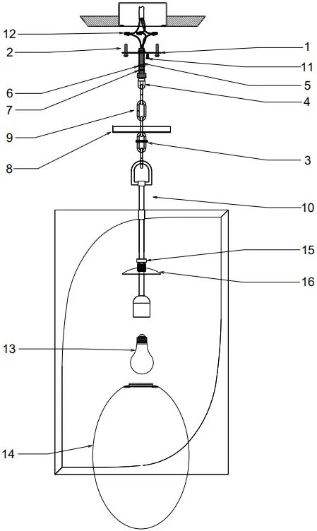
| ITEM | DESCRIPTION | PART NUMBER |
| 1 | MOUNTING PLATE | HDW-F1213 |
| 2 | MOUNTING SCREW | HDW-F1213 |
| 3 | SCREW COLLAR | HDW-F1213 |
| 4 | COLLAR LOOP | CAS-F1213 |
| 5 | NIPPLE | HDW-F1213 |
| 6 | HEX NUT | HDW-F1213 |
| 7 | TOOTH WASHER | HDW-F1213 |
| 8 | CANOPY | CAS-F1213 |
| 9 | CHAIN | CHN-F1213 |
| 10 | FIXTURE ASSEMBLY | FAS-F1218 |
| 11 | GROUND SCREW | HDW-F1213 |
| 12 | WIRE NUT | HDW-F1213 |
| 13 | BULB | NOT INCLUDED |
| 14 | GLASS | GLS-F1218 |
| 15 | THREADED COLLAR | HRD-F1213 |
| 16 | FITTER | FIT-F1218 |
 WARNING/CAUTION
- DISCONNECT POWER BEFORE RE-LAMPING OR WIRING THE FIXTURE. READ ALL INSTRUCTIONS COMPLETELY BEFORE STARTING INSTALLATION.
- TO AVOID THE RISK OF FIRE OR SHOCK, THE FIXTURE MUST BE INSTALLED IN COMPLIANCE WITH ALL APPLICABLE NATIONAL AND LOCAL ELECTRICAL/BUILDING CODES. THE INSTALLATION AND MAINTENANCE OF THIS UNIT SHOULD BE COMPLETED BY A LICENSED ELECTRICIAN OR CERTIFIED FACTORY-TRAINED TECHNICIAN.
- CALIFORNIA PROP 65: THIS LIGHTING FIXTURE CONTAINS CHEMICALS KNOWN TO THE STATE OF CALIFORNIA TO CAUSE CANCER, BIRTH DEFECTS, AND/OR OTHER REPRODUCTIVE HARM. WASH HANDS AFTER USE.
- REMOVE THE FIXTURE, PARTS, AND PARTS BAG(S) FROM THE CARTON. BEFORE DISCARDING THE CARTON, DOUBLE-CHECK TO MAKE CERTAIN THAT ALL PARTS ARE FOUND. INSPECT THE FIXTURE PRIOR TO INSTALLATION FOR ANY DAMAGE TO THE FIXTURE.
- DIMMING: THE FIXTURE CAN BE CONTROLLED BY A WALL-DIMMING DEVICE. ONLY USE TRIAC/ELECTRONIC DIMMER. MAKE SURE THE CARTON IS MARKED FOR USE WITH LED COMPACT FLUORESCENT-INCANDESCENT LIGHT SOURCE ONLY. THESE CAN BE PROVIDED BY YOUR LOCAL ELECTRICAL DISTRIBUTOR, HOME CENTER, OR HARDWARE STORE.
- PLEASE CLEAN WITH A SOFT, DRY CLOTH ONLY! DO NOT USE CLEANERS
FIXTURE INSTALLATION
- Attach the MOUNTING PLATE (1) onto the junction box using the MOUNTING SCREWS (2). This fixture is designed to be mounted on a standard round or octagon junction box. The junction box must be securely mounted to the structure of the building.
- Remove the SCREW COLLAR (3) from the COLLAR LOOP (4). Fully thread the NIPPLE (5) onto the COLLAR LOOP (4). Thread the HEX NUTS (6) onto the NIPPLE (5) along with TOOTH WASHER (7). Then thread the NIPPLE (5) unto the MOUNTING PLATE (1). Adjust the NIPPLE (5) so that the threads of the COLLAR LOOP (4) extend 1/4″ beyond the CANOPY (8). Secure using HEX NUT (6).
- Open the end link of the CHAIN (9) and attach it to the FIXTURE ASSEMBLY (10) at the desired height. Slide the SCREW COLLAR (3) and the CANOPY (8) onto the CHAIN (9). Attach the other end of the CHAIN (9) to the COLLAR LOOP (4). Feed the wires through the CHAIN (9), SCREW COLLAR (3), CANOPY (8), COLLAR LOOP (4), NIPPLE (5), and MOUNTING PLATE (1).
- Cut off excess wires, and strip the insulation off the end of the leads.
- Attach the Ground wire (Green) to the ground inside the junction box (Generally green or bare copper wire) or the GROUND SCREW (11) on the MOUNTING PLATE (1). NEVER CONNECT GROUND WIRE TO “HOT” WIRE! FAILURE TO FOLLOW THIS COULD RESULT IN SERIOUS INJURY OR DEATH!
- Connect the fixture’s SPT Neutral (SPT WIRE WITH NO WRITINGS) wire lead to the neutral (Generally white) wire in the outlet box. Fasten the wires together with an approved fastener (WIRE NUT) (12). Starting 1″ below the fastener, tightly wrap the connection with electrical tape so that the connection seals the end of the fastener. MAKE SURE THERE IS NO EXPOSED WIRE OR STRANDS THAT COULD CAUSE A DANGEROUS SHORT CIRCUIT!
- Connect the fixture’s SPT hot (SPT WITH WRITINGS) wire lead to the hot (Generally black) wire in the junction box. Fasten the joined wires the same as in the previous step. NEVER REVERSE HOT AND NEUTRAL WIRES. FAILURE TO FOLLOW THIS COULD RESULT IN SERIOUS INJURY OR DEATH!
- Push the wires back into the junction box. Lift up the CANOPY (8) up to the ceiling, and screw the SCREW COLLAR (3) onto the COLLAR LOOP (4).
- Screw the BULB (13) up into the SOCKET of the fixture. THIS FIXTURE IS RATED FOR 75 WATT TYPE OF LAMP. DO NOT EXCEED THE RECOMMENDED WATTAGE!
- Untighten the THREADED COLLAR (15) from FITTER (16) allowing the glass over to make space for the GLASS (14). Place the GLASS (14) beyond the glass holder. (NOTE: Please handle the GLASS (14) with care when putting it in the glass holder). Tighten back the THREADED COLLAR (15) to FITTER (16) just enough to hold the GLASS (14).
- Restore power to the outlet at the breaker or fuse box.
![]() Questions? We’re here to help!
Questions? We’re here to help!
Contact us at [email protected]
F1218


