
![]()
32.6cc GASOLINE POLE SAW

| This product can expose you to chemicals including LEAD/CADMIUM/DEHP, which is known to the State of California to cause cancer and birth defects, or other reproductive harm. For more information go to www.P65Warnings.ca.gov. |
*Actual product may vary slightly
Please carefully read and save these instructions before attempting to assemble, maintain, install, or operate this product.
Observe all safety information to protect yourself and others. Failure to observe the instructions may result in property damage and/or personal injury. Please keep instructions for future reference.
For warranty purchases, please keep your dated proof of purchase. File or attach to the manual for safekeeping.
IMPORTANT SAFETY INSTRUCTIONS
PLEASE SAVE THIS OWNERS MANUAL AND READ IT BEFORE EACH USE.
This manual will explain how to use the solar panel kit safely and effectively.
Please read and follow these instructions and precautions carefully.
CALIFORNIA PROPOSITION 65
WARNING:
You can create dust when you cut, sand, drill, or grind materials such as wood, paint, metal, concrete, cement, or other masonry. This dust often contains chemicals known to cause cancer, birth defects, or other reproductive harm. Wear protective gear.
WARNING:
This product or its power cord may contain chemicals, including lead, known to the State of California to cause cancer and birth defects, or other reproductive harm. Wash hands after handling.
IMPORTANT!
When using equipment, a few safety precautions must be observed to avoid injuries and damage. Please read the complete operating manual with due care. Keep this manual in a safe place, so that the information is available at all times. If you give the equipment to any other person, give them these operating instructions as well. We accept no liability for damage or accidents which arise due to the non-observance of these instructions and the safety information herein.
 |  |
 |  |
 |  |
| When using the equipment, a few safety precautions must be observed to avoid injuries and damage. Please read the complete operating instructions and safety regulations with due care. Keep this manual in a safe place, so that the information is available at all times. If you give the equipment to any other person, hand over these operating instructions and safety regulations as well. We cannot accept any liability for damage or accidents which arise due to a failure to follow these instructions and the safety instructions. |
Safety information
For the relevant safety information please refer to the booklet included in the delivery.
![]() Warning!
Warning!
Read all the safety information and instructions.
Any errors made in following the safety information and the instructions set out below may result in an electric shock, fire, and/or serious injury. Keep all safety information and instructions in a safe place for future use.
Explanation of the symbols on the equipment
| Warning! | Protect the equipment from rain and dampness. | ||
| Wear protective headgear, goggles, and earmuffs | Always switch off the equipment and pull out the spark boot plug before carrying out any maintenance work. | ||
| Wear safety gloves. | Electric shock can cause fatal injury. Keep a distance of at least 10 m from power cables. | ||
| Watch out for falling and catapulting parts. | Direction of the chain movement and teeth. | ||
 | Read the directions for use before operating the equipment. | Caution: Hot equipment parts. Keep your distance. | |
 | Wear sturdy, non-slip footwear. | Sound power level guaranteed |
Layout and items supplied
| 2.1 Layout | |
| 1. Cutter bar 2. Saw chain 3a. Oil tank/cap 3b. Gear unit 4. Drive rod mechanism 5. Connecting piece 6. Additional handle 7. Eyelet 8. Handle 9. On/Off switch 10. Throttle lock 11. Throttle lever 12. Spark plug boot 13. Starter cable 14. Petrol tank/cap | 15. Air filter housing cover 16. Choke lever 17. Clip 18. Screw (4x) 19. Open-ended wrench size 8/10 20. Allen key 21. Cutter guard 22. Carrying strap 23. Oil/petrol mixing bottle 24. Multifunction tool 25. Lubrication nipple 26. Fuel pump “primer“ |
2.2 Items supplied
- Open the packaging and take out the equipment with care.
- Remove the packaging material and any packaging and/or transportation braces (if available).
- Check to see if all items are present.
- Inspect the equipment and accessories for transport damage.
- If possible, keep the packaging until the end of the guarantee period.
Important!
The equipment and packaging material are not toys. Do not let children play with plastic bags, foils, or small parts. There is a danger of swallowing or suffocating
- Original operating instructions
- Safety information
Intended use
The pole-mounted petrol-powered pruner is designed for lopping off tree branches. It is not suitable for extensive sawing work, felling trees, or sawing any materials other than wood.
The equipment may be used only for its intended purpose. Any other use is deemed to be a case of misuse.
The user/operator and not the manufacturer will be liable for any damage or injuries of any kind which result from such misuse.
Please note that our equipment has not been designed for use in commercial, trade, or industrial applications. Our warranty will be voided if the equipment is used in commercial, trade, or industrial businesses or for equivalent purposes.
Technical data
| Engine type: | 2-stroke engine, air-cooled,chrome cylinder |
| Engine power (max.): | 0.85 kW/ 1.14 HP |
| Displacement: | 32.6cc |
| Engine idle speed: | 3400 RPM |
| Max. engine speed: | 9500 RPM |
| Max. cutting length: | 245 mm |
| Weight with cutter bar and chain: | 7.6 kg |
| Chain: | 10”, 3/8”, 0.050” |
| Cutter bar: | 10”, 3/8”, 0.050” |
| Ignition: | Electronic |
| Drive: | Centrifugal clutch |
| Tank capacity: | 825 ml |
| Spark plug: | L7T |
| Sound and vibration | |
| LpA sound pressure level: | 93,9 dB(A) |
| KpA uncertainty: | 2,5 dB |
| LWA sound power level: | 108,2 dB(A) |
| KWA uncertainty: | 2,5 dB |
Wear ear-muffs.
The impact of noise can cause damage to hearing.
In operation
Vibration emission value a, = 6,888 m/s2
K uncertainty = 1,5 m/s2
Reduce noise generation and vibration to a minimum!
- Use only equipment that is in perfect condition.
- Maintain and clean the equipment regularly.
- Adopt your way of working to the equipment. • Do not overload the equipment.
- Has the equipment been checked if necessary?
- Switch off the equipment when not in use.
- Wear gloves.
Assembly
Important!
Do not start the chainsaw until it has been fully assembled and the chain tension has been adjusted.
Always wear protective gloves when working on the chainsaw to protect yourself against injury.
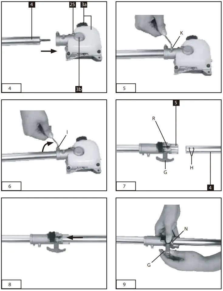
5.1 Joining the gear unit to the drive rod mechanism (Fig. 4-6)
Tools required: Allen keys size 4mm/5mm (supplied) Push the gear unit (Item 3b) and the drive rod mechanism (Item 4) into each other.
Center both by turning the screw (Item K).
Important! Make sure that the screw (Item K) is turned exactly into the guide hole (Item F).
Otherwise, there is a risk of the upper part of the rod mechanism being damaged. To join the two subassemblies securely together, tighten the screw (Item I). To take apart, proceed in reverse order.
5.2 Joining the drive rod mechanism to the connecting piece (Fig. 7-10)
Open the handle screw (Item G) and push the drive rod mechanism (Item 4) into the connecting piece (Item 5). Make sure that the centering lever (Item R) latches in the guide hole (Item H). Close the guard cap (Item N) and tighten the handle screw. To take apart, undo the handle screw and open the guard cap. Press the centering lever and simultaneously pull the drive rod mechanism out of the connecting piece.
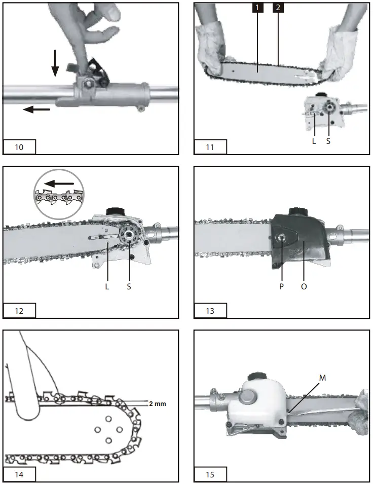
5.3 Fitting the cutter bar and the chain (Fig. 11-16)
Tools required: Allen key size 5mm
Remove the chain wheel cover (Fig.13/ Item O) by undoing the fastening screw (Item P). Lay the chain (Item 2) as shown into the groove which runs around the cutter bar (Item 1). Note the alignment of the chain teeth (Fig. 12). Insert the cutter bar as shown in Fig. 12 into the mount at the gear unit. Place the chain around the chain wheel (Item S). Make sure that the teeth of the chain engage securely in the chain wheel.
The cutter bar must be hooked into the chain tensioning bolt (Item L).
Fit the chain wheel cover.
Important! Do not fully tighten the fastening screw until after you have adjusted the chain tension (see section 5.4).
5.4Tensioning the chain (Fig. 14-16) Important! Always pull out the spark boot plug before performing any checks or adjustments. Undo the fastening screw (Item P) of the chain wheel cover by a few turns (Fig. 13). Adjust the chain tension with the chain tensioning screw (Fig. 15/Item M). Turning the screw clockwise increases the chain tension, turning it counterclockwise decreases the chain tension. The chain is correctly tensioned if it can be raised by around 2 mm in the middle of the cutter bar (Fig. 14).
Tighten the fixing screw of the chain wheel cover (Fig. 16).
Important! All the chain links must lie properly in the guide groove of the cutter bar.
Notes on tensioning the chain:
The chain must be properly tensioned to ensure safe operation. When the saw chain can be raised by around 2 mm in the middle of the cutter bar, you know that the chain tension is ideal. During cutting, the temperature of the chain rises and its length changes. It is important therefore to check the chain tension at least every 10 minutes and to adjust it again as required. This applies in particular to new saw chains. When you have finished working, slacken the chain again as it will shorten when it cools down. This will help to prevent damage to the chain.
5.5 Fitting the additional handle
Fit the additional handle as shown in Fig. 17-18.
Before starting
Each time before use, check the following:
- That there are no leaks in the fuel system.
- That the equipment is in perfect condition and that the safety devices and cutting devices are complete.
- That all screws are securely fastened.
- That all moving parts move smoothly.
6.1 Fuel and oil
Recommended fuels
Use only a mixture of unleaded petrol and special 2-stroke engine oil. Mix the fuel mixture as indicated on the fuel mixing table.
Important: Do not use a fuel mixture that has been stored for longer than 90 days.
Important: Never use 2-stroke oil with a recommended mixing ratio of 100:1. The manufacturer’s warranty will be voided in case of engine damage due to inadequate lubrication. Important: Only use containers designed and approved for the purpose to transport and storing fuel.
Pour the correct quantities of petrol and 2-stroke oil into the mixing bottle (see scale printed on the bottle). Then shake the bottle well.
6.2 Fuel mixing table
Mixing procedure: 40 parts petrol to 1 part oil
Petrol | 2-stroke oil |
1 liter | 25 ml |
5 liters | 125 ml |
6.3 Chain lubrication
Important! Never operate the chain if it is not lubricated with saw chain oil. Use of the chainsaw without saw chain oil or if the oil level is below the „min“ mark will damage the chainsaw.
Important! Be aware of the temperature conditions: Different lubricants with completely different viscosities are required at different ambient temperatures. At lower temperatures, you will need low viscosity oils in order to achieve a sufficient lubricating film. However, if the same low viscosity oil is used during the summer it will become even thinner due to the ambient temperatures alone, and as a result, the lubricating film could break down, causing the chain to overheat and become damaged. In addition, the chain oil would burn and produce unnecessary pollutants.
Filling the oil tank (Fig. 1):
Place the chainsaw on a flat surface. Clean the area around the oil tank cap (Fig. 3a) and then clean the oil tank cap.
Fill the tank (Item 3a) with saw chain oil. In the process, make sure that no dirt enters the tank, as this could cause the oil nozzle to become blocked. Close the oil tank cap.
Operation
Please note that the statutory regulations governing noise abatement may differ from one location to another.
7.1 Starting with a cold engine
Fill the tank with the required amount of oil/ petrol mix. See”Fuel and oil”.
- Set the equipment down on a hard, level
- Press the fuel pump (primer) (Fig. 2/Item 26) 10 times.
- Move the On/Off switch (Fig. 2/Item 9) to”I”.
- Set the choke lever (Fig. 2/Item 16) to “OFF”.
- Hold the equipment firmly and pull out the starter cable (Fig. 2/Item 13) until you feel it begin to resist. Then tug sharply on the starter cable 4 times. The equipment should start.
Important: Never allow the starter cable to snap back. This may result in damage.
Once the engine has started, move the choke lever immediately to “ON“ and allow the equipment to warm up for approx. 10 seconds.
Important: Since the throttle lever is secured, the cutting tool starts to operate when the engine is started.
Then release the throttle lever by actuating it once.
6. If the engine does not start up, repeat steps 4-6 above.
Please note: If the engine does not start up even after several attempts, read the section “Engine troubleshooting“.
Please note: Always pull the starter cord out in a straight line. If it is pulled out at an angle, then friction will occur on the eyelet. As a result of this friction, the cable will become frayed and will wear away faster. Always hold the starter handle when the cable retracts.
Never allow the cable to snap back when it has been pulled out.
7.2 Starting with a warm engine
(The equipment has been idle for less than 15-20min.)
- Set the equipment down on a hard, level
- Switch the On/off switch to “I”.
- Secure the throttle lever (in the same way as described in “Starting with a cold engine”).
- Hold the equipment firmly and pull out the starter cable until you feel it start to resist. Then tug sharply on the starter cable. The equipment should start after 1-2 tugs. If the equipment does not start after 6 pulls, repeat steps 1 – 7 of the procedure for starting the engine from cold.
7.3 Long time unused machine restart
Unused machine be in storage for longer than 90days, the ignition coil is not damaged, it’s only carburetor issue. Please follow these instructions to restart the machine.
7.3.1 Check either the fuel pipe is aging or cracking, if any, easy to buy a new one for replacement at a local store.
7.3.2. Check either the fuel pipe joint of carburetor loosening or aging, if any, cut the pipe joint a little bit to rejoin as well.
7.3.3. Please pull the starting rope 5-8 times before fuel refilling to the carburetor is in an operating state.
7.3.4. Refilling the fuel and then restart the machine according to the cold start mode.
7.4 Emergency Stop procedure:
If it becomes necessary to stop the equipment immediately, set the On/Off switch to “Stop” or “0”.
Normal procedure:
Let go of the throttle lever and wait until the engine has changed to idling speed. Then set the On/Off switch to “Stop” or “0”.
7.5 Fitting the shoulder strap
Important! Always use the shoulder strap when Working with the equipment. Switch off the equipment before you take off the shoulder strap (risk of injury).
- Slip the shoulder strap over your shoulder.
- Adjust the length of the shoulder strap so that the strap attachment is at waist level.
7.6 Work practice
Practice all the work steps with the engine switched off before you start to use the equipment.
Working with the chainsaw
Preparations
To ensure that you can work safely, check the following points before every use:
Condition of the chainsaw
Before you start your work, inspect the chainsaw for damage to the housing, the chain, and the cutter bar. Never use a chainsaw which is obviously damaged.
Oil container
Level of oil in the oil container Both before and during your work make sure that there is always sufficient oil in the system. To avoid damaging the chainsaw, never run the saw if there is no oil in the system or if the oil drops below the „min” mark. On average, a single filling will last around 10 minutes depending on the number of pauses in cutting and the loads involved.
Chain
Tension of the chain, condition of the cutting
elements: The sharper the chain, the easier and more controllable it is to operate the chainsaw.
The same also applies to the chain tension. For greater safety, you must check the chain tension before your work and at least every 10 minutes during your work. New chains in particular tend to expand more.
Safety clothing
Always wear appropriate tight-fitting safety clothing such as special trousers which protect against cuts, protective gloves, and safety shoes.
Hearing protection and protective goggles
Wear a protective helmet with integral face and hearing protection. This will offer protection against falling branches and recoiling branches.
Safe working
Never stand under the branch you want to see.
Use special caution when working with branches under tension and splintering wood.
Possible risk of injury caused by falling branches and catapulting pieces of wood.
When the equipment is in operation, keep other persons and animals away from the danger zone.
The equipment is not protected from electric shock through contact with high-voltage cables.
Keep a minimum distance of 10 m from live cables. Electric shock can cause fatal injury.
When working on slopes always stand to the upper or left or right side of the branch you want to cut.
Hold the equipment as close as possible to your body. This will help you to keep your balance.
Cutting techniques
Start with the bottom branches on the tree. This will make it easier for the cut branches to drop.
After completing a cut, the weight of the saw will abruptly increase for the operator as the saw is no longer supported by the branch. This can result in you losing control over the saw.
Remove the saw from the cut only with the saw chain still running. This will prevent the saw from getting jammed.
Never cut with the tip of the saw.
Never cut into the bulging branch collar. This will prevent the tree from healing.
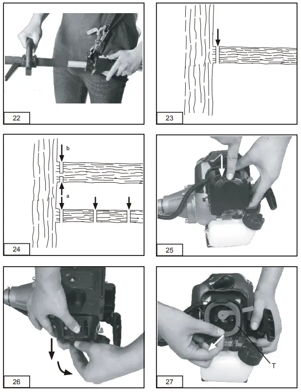
Sawing off smaller branches (Fig. 23):
Place the contact surface of the saw onto the branch. This will prevent the saw from making jerky movements when you begin a cut. Exerting slight pressure, guide the saw from the top to the bottom through the branch.
Sawing off large and long branches (Fig. 24):
Carry out a relief cut when working on large branches.
Start by sawing through 1/3 of the branch diameter (a) from the top to the bottom with the top side of the cutter bar. Then saw towards the first cut (b) from the top to the bottom with the bottom side of the cutter bar.
Saw off long branches in several steps to keep control over the impact location.
Kick-back
The term „kickback” describes what happens when the running chainsaw suddenly kicks upward and backward. Usually, this is caused by contact between the tip of the cutter bar and the workpiece or by the saw chain becoming trapped.
In the event of kickback, large forces occur suddenly and violently. As a result, the chainsaw usually reacts uncontrollably. This can often result in very serious injuries to the worker or persons in the vicinity. The risk of kickback is at its greatest when the saw is positioned for a cut in the region of the tip of the cutter bar, as the leverage effect is greatest there. It is, therefore, safest to position the saw as flat as possible.
Important!
- Make sure that the chain tension is always correctly adjusted.
- Only use a chainsaw if it is in perfect working order.
- Never cut with the upper edge or the tip of the cutter bar.
- Always hold the chainsaw firmly with both nly works with a saw chain that has been properly sharpened in accordance with the instructions.
Cutting wood which is under tension Special care is required when cutting wood which is under tension. Cutting wood which is under tension can release the tension, causing the wood to react out of control. In the worst case, this can result in severe and even fatal injuries. This type of work must be performed only by specially trained persons.
Maintenance
9.1 Replacing the chain and cutter bar
The cutter bar needs to be replaced if • the guide groove of the cutter bar is worn.
Proceed as described in the section „Fitting the cutter bar and the chain“.
9.2 Checking the automatic chain lubrication
You should check the operation of the automatic chain lubrication system on a regular basis in order to guard against overheating and the damage this can cause to the cutter bar and the chain.
Point the tip of the cutter bar at a smooth surface (a board or a cut tree face) and allow the chainsaw to run. If you see a growing oil stain on the smooth surface, the automatic chain lubrication system is working properly. If there is no clear oil stain, please refer to the corresponding instructions in the section „Troubleshooting“. If the information
contained there still fails to remedy the situation, please contact our service department or another similarly qualified workshop.
Important! Do not actually touch the surface with the tip of the cutter bar when performing this test.
Keep a safe distance (approx. 20 cm).
9.3 Sharpening the chain
Working effectively with the chainsaw is only possible if the chain is in good condition and sharp.
This also reduces the risk of kickback.
The chain can be re-sharpened by any dealer. Do not attempt to sharpen the chain yourself unless you have the necessary special tools and experience.
9.4 Maintenance of the air filter (Fig. 25-27)
Soiled air filters reduce the engine power by supplying too little air to the carburetor. Regular checks are therefore essential. The air filter (T) should be checked after every 25 hours of use and cleaned if necessary. If the air contains a lot of dust, the air filter should be checked more frequently.
- Remove the air filter cover (Fig. 25-26).
- Remove the air filter (Fig. 27).
- Clean the air filter by tapping it or blowing it out.
- Assemble in reverse order.
Important: Never clean the air filter with petrol or inflammable solvents.
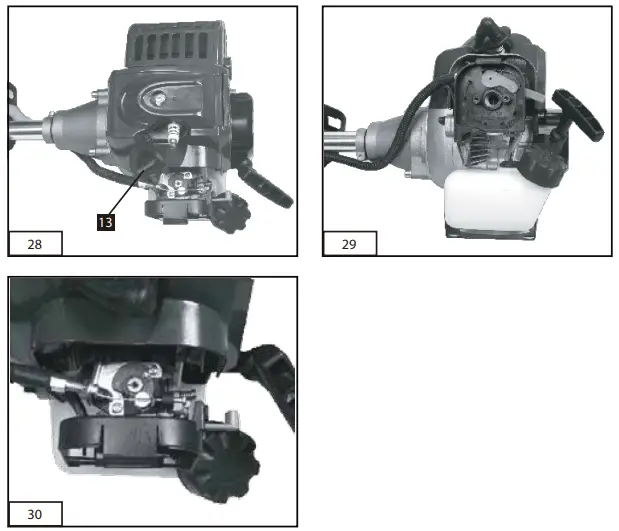
9.5 Maintenance of the spark plug (Fig. 27)
Spark plug sparking gap = 0.6mm. Tighten the spark plug with a torque of 12 to 15 Nm. Check the spark plug for dirt and grime after 10 hours of operation and if necessary clean it with a copper wire brush. Thereafter service the spark plug after every 50 hours of operation.
- Pull out the spark boot plug (Fig. 28).
- Remove the spark plug (Fig. 28) with the supplied multifunction tool (Item 24).
- Assemble in reverse order.
9.6 Applying grease to the gear unit
After every 20 hours of use add a little gear grease (approx. 10 g.) at the lubrication nipple (Fig. 4/Item 25).
Cleaning, storage, transport
10.1 Cleaning
- Regularly clean the tensioning mechanism
by blowing it out with compressed air or
cleaning it with a brush. Do not use any tools for cleaning. - Keep the handles free of oil so that you can maintain a firm grip.
- Clean the equipment as required with a damp cloth and, if necessary, mild washing up liquid.
- If you are not going to use the chainsaw for an extended period of time, remove the chain oil from the tank. Briefly immerse the saw chain and the cutter bar into an oil bath and then wrap them in oil paper.
Important!
Always pull out the spark boot plug each time before carrying out any cleaning. Never immerse the equipment in water or other liquids in order to clean it.
Store the chainsaw in a safe and dry place out of the reach of children.
10.2 Storage
Important: Never put the equipment into storage for longer than 30 days without carrying out the following steps.
Storing the equipment
If you intend to store the equipment for longer than 30 days, the equipment must be prepared accordingly. Otherwise, the fuel still remaining in the carburetor will evaporate and leave rubbery sediment. This can cause problems when starting up the equipment and may require expensive repairs.
- Slowly remove the fuel tank cap to release any pressure that may have formed in the tank. Carefully empty the tank.
- To remove the fuel from the carburetor, start the engine and let it run until the equipment stops.
- Leave the engine to cool (approx. 5 minutes).
- Remove the spark plug (see section 9.5).
- Add one teaspoon of 2-stroke engine oil into the combustion chamber. Slowly pull the starter cord several times to apply a layer of oil to all internal components. Fit the spark plug again.
Note:
Store the equipment in a dry place and far away from possible ignition sources such as an oven, a gas-fired hot water boiler, a gas-fired dryer, etc.
Putting the equipment back into operation
- Remove the spark plug (see section 9.5).
- Quickly tug on the starter cord to remove excess oil from the combustion chamber.
- Clean the spark plug and check that the electrode gap is correct, or insert a new spark plug with the correct electrode gap.
- Prepare the equipment for operation.
- Fill the tank with the relevant mixture of fuel and oil. See the section „Fuel and oil”.
10.3 Transport
To transport the machine, empty the petrol tank as described in section 10. Clean coarse dirt off the equipment with a brush or hand brush. Dismantle the drive rod mechanism as described in section 5.2.
Disposal and recycling
 | The equipment is supplied in packaging to prevent it from being damaged in transit. The raw materials in this packaging can be reused or recycled. The equipment and its accessories are made of various types of material, such as metal and plastic. Defective components |
Troubleshooting guide
The table below contains a list of fault symptoms and explains what you can do to remedy the problem if your equipment fails to work properly. If the problem still persists after working through the list, please contact your nearest service workshop.
| Fault | Possible cause | Remedy |
| The equipment does not start | – Correct starting procedure not followed – Sooted or damp spark plug – Incorrect carburetor setting | – Follow the instructions for starting – Clean the spark plug or replace it with a new one – Contact authorized customer service. |
| The equipment starts but does not develop its full power | – Incorrect choke lever setting – Soiled air filter – Incorrect carburetor setting | – Set the choke lever to “ON”. – Clean the air filter – Contact authorized customer service. |
| The engine does not run smoothly | – Incorrect electrode gap on the spark plug – Incorrect carburetor setting | – Clean the spark plug and adjust the electrode gap, or fit a new spark plug – Contact authorized customer service. |
| Engine smokes excessively | – Incorrect fuel mix – Incorrect carburetor setting | – Use the correct fuel mix (see fuel mixing table) – Contact authorized customer service. |
| Saw chain is dry | – No oil in the tank – Vent in the oil tank cap is blocked – Oil outlet blocked | -Top up with oil – Clean the oil tank cap – Clear the oil outlet |
| Chain/guide bar is hot | – No oil in the tank – Vent in the oil tank cap is blocked – Oil outlet is blocked – Chain is blunt – Chain is over tensioned | -Top up with oil – Clean the oil tank cap – Clear the oil outlet – Re-sharpen or replace the chain – Check the chain tension |
| Chainsaw judders vibrate or do not see properly | – Chain is under tensioned – Chain is blunt – Chain is worn – Sawteeth point in the wrong direction | – Adjust the chain tension – Re-sharpen or replace the chain – Replace the chain – Refit the chain with the teeth facing in the correct direction |
Parts List
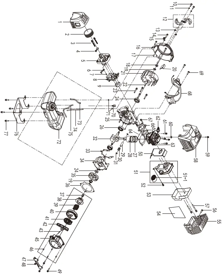 |
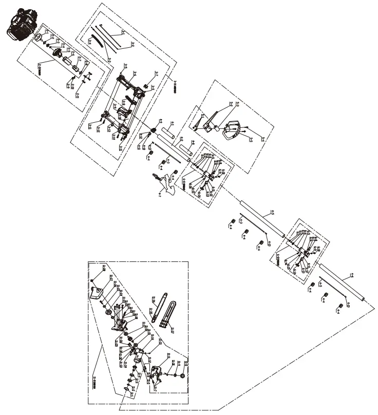 |
| Part No. | Description | Quantity | Pan No. | Description | Dummy | Pan No. | Description | |
| I | air alter WO | 1 | 60 | cylinder mask heat Drawee: in gasket | I | 5-2 | P handle bottom cover | |
| 2 | filter sponge | I | 61 | hex. screw M5x20 | 4 | 5-3 | shock rubber cover | |
| 3 | hex. sinew M5’55 | 2 | 82 | spark plug | 1 | 5-4 | hex.screw k45’30 | |
| 4 | ventilation door baffle | I | 63 | cylinder | 1 | 5-5 | P handle top cover | |
| 5 | MON body | I | 64 | cylinder gasket | ‘ | 6-0 | tube ccnnecban assembly(6-1.6-2.6- 3.6-4.6-6.6-6.6-7.6-13.6-9.6-10.6-11.6- 12.6-13.6-14.) | |
| 6 | ventilation door trigger | I | 65 | air Intake tube gasket | • | 6-1 | ceche GB/7 893.1 26 | 2 |
| 7 | cross components screw 572.9’8 | I | 66 | in air take tube | 1 | 6-2 | drat 08/T894.1 9 | 2 |
| 8 | carburetor | I | 67 | hex. screw MS x 20 | 2 | 8-3 | 0000 grOeve bell bearing GEVT 278 60985 | |
| 9 | carburetor gasket | 1 | 88 | ignitor | i | 8-4 | shaft connect cover ( y teem) | |
| 10 | ClulCh bolt | 2 | 69 | hex. SOWN 4.45 x 20 | 2 | 6-5 | tube 00nneCt cover 026 | 2 |
| 11 | spring washer | 2 | 70 | balancer | 1 | 6-6 | torsional spring | 2 |
| 12 | clutch aesernbly | 1 | 71 | cylinder meek heat protection gasket | 2 | 6-7 | hex.screw GB/T 70.1 M54 10 | 2 |
| 13 | flat washer 0841841.2 | 2 | 72 | fuel tank assembly | I | 6-8 | hex. nut GEVT 41 M8 | 2 |
| 14 | hex. screw M5’20 | 3 | 73 | fuel return tube 02.5x M4.5 x 90 | 1 | 8-9 | spring | 2 |
| 15 | Beton buckle | 1 | 74 | breather Wee 054 3 x 110 | 1 | 6-10 | tooth shape Wee | 7 |
| 16 | flywheel case cover | 1 | 75 | fuel tute 03.1)(06.3 x 200 | 1 | 6-11 | round pin 0648420.6 | 2 |
| 17 | pin GEUT 119.1 5410 | 4 | 76 | fuel tank rigger | 1 | 6-12 | limiting plate | 2 |
| 18 | hex.flange nut M8 | 2 | 77 | hex. screw M5 x 20 | a | 6-13 | flat washer °SOT 97.1 8 | 7 |
| 19 | flat washer 8×1641.5 | 1 | 2-0 | output base assembly (2-t,2-2.24.24. 2- 5.25.2-7.25) | 6-14 | knOb | 2 | |
| 20 | air deflector | I | 2-1 | clutch shell | 1 | 6-15 | hex. screw M5412 | 2 |
| 21 | flywheel | I | 24 | drag:, Gorr 893.1 35 | 6-16 | life.screw M5425 | 7 | |
| 22 | semicircular key 3•13 | 1 | 24 | deep groove ball bearing GINT 276 6202RS | . | 7-0 | polo sew hood assembly t 7-1J-2.7- 3,7-4.7-15.7-6,7-7.7-8.74k7-10.7-11,7- 12,7-13,7-14,7-115.7-16,7-17.7-113.7- 19.7-20.7-21.7-22.7-23.7-24. 7-25.7- 03.7-27.7-28.7-29.7-30.7-31.7-32.7- 33.7-341 | |
| 23 | hex. Salim 1.15–30 | 4 | 2-4 | CirdipOINT 894.1 15 | 7-1 | circlip 05T 893.1 26 | ||
| 24 | oil seal 1242247 | 2 | 2-5 | alurniniurn tube connecting base | 7-2 | cirdip 013fT 894.1 10 | 1 | |
| 25 | top case | 1 | 24 | rubber damping cover | 7-3 | • 276 deep groove ball beanng 05/1 600082 | 2 | |
| ze | deep glove bell bearing 05)7 276 6201 | 2 | 2-7 | alarmism tube retaming clip | • | 7-4 | driving gear | |
| 27 | Piston ring | 2 | 24 | circlip GIN/T 893.1 45 | 1 | 75 | hex.crew GEtfT 70.111/445 x 25 | |
| 28 | Piston | I | 24 | hex. Maim M13420 | 1 | 74 | nex.eCrew GEVT 70.1 M5 x 12 | 1 |
| 29 | Piston pm | 1 | 2-10 | hex. screw M5 x 12 | 1 | 7-7 | nex.screw °SOT 70.1 645 x 12 | a |
| 30 | needle tear NA9412x12 | 1 | 2-11 | hex. screw N16 x 30 | 4 | 74 | el tank cap | 1 |
| 31 | piston pm Jump ring | 2 | 3-0 | handle assembly 3-1.3-2.3-3.3-4.3-5. 3-6.3-7. 36,3-9.3-10.3-11,3-12.3-13,3-14) | 7-9 | dl tank cap packing washer | ||
| 32 | crankshaft | 1 | 3-1 | choke cable | 1 | 7-10 | of tank CAP retainer | |
| 33 | crankshaft case gasket | 1 | 3-2 | ground wire | 7-11 | al tank | ||
| 34 | bottom cave | I | 3-3 | accelerator cable | 1 | 7-12 | flat washer 06 x 012×1 | 1 |
| 35 | startup disk component,: | 1 | 3-4 | bellows | 1 | 7-13 | grease tung | |
| 36 | starter gasket | I | 3-5 | not MS | 2 | 7-14 | gem case | |
| 37 | screw ki5x9 | 1 | 34 | loft horde body | 1 | 7-15 | deep groove ball tearing 013/T 276 627Z | i |
| 38 | 1 | 3-7 | flameout switch | 1 | 7-18 | driven gear | 1 | |
| tart wheel | ||||||||
| man %Primo | 1 | 3-8 | control am, | 1 | 7-17 | deep groove ball bearing GB/T 276 6001Z | ||
| 40 | reel | I | 3-9 | trigger | 1 | 7-18 | baseboard | 1 |
| 41 | mart coil spring | 1 | 3-10 | Mager seasonal *OMB | 1 | 7-19 | tensioning Nock | |
| 42 | starting handle | 1 | 3-11 | cross components screw GLVT1345 ST 3 x10 | 2 | 7-20 | split washer 05)1 806 3.5 | |
| 43 | rope | 1 | 3-12 | cross components screw GLUT 1345 ST 3.9 x 18 | 4 | 7-21 | tensioning bolt | |
| 44 | easy starter cover | 1 | 3-13 | right handle body | 1 | 7-22 | gasket | |
| 45 | copper damper 05.07.6 | 4 | 3-14 | cross components screw 572.5×8 | 1 | 7-23 | hox.scrow Gen 70.1 M6412 | 4 |
| 46 | fuel tank retainer | I | 4-1 | sponge cover 140mrn | 1 | 7-24 | sprocket wheel | 1 |
| 47 | hex. screw M5x20 | 3 | 4-2 | rear aluminum tube | 1 | 7-25 | flat washer 06 x 018×1 | 1 |
| 48 | hex. screw )45425 | I | 4-3 | ft shaft | 3 | 7-26 | hox.escrow Gbit 70.1 M6x14 | |
| 49 | muffler gasket | I | -4 4 | oiliness shalt sleeve | 9 | 7-27 | left board | |
| 50 | muffler | 1 | 44 | middle aluminum tube | 1 | 7-28 | hex.large face nut GSM 8177.1 MB | 1 |
| 51 | catalyst | i | 4-8 | front aluminum lobe | 2 | 7-29 | stud tell MB x 30 | 1 |
| 52 | hex. screw M5414 | t | 4-7 | belt(quick release) | 1 | 7-30 | hex.screw G13/7 70.1 M4 x 12 | 2 |
| 63 | muffler shell | I | 441 | sponge cover 120mm | 7-31 | spring washer GEUT 934 | 2 | |
| 54 | muffler cover aluminized paper | t | 44 | belt base | 1 | 7-32 | sponge filter mig | |
| 55 | muffles cover | I | 4-10 | Pox. CONTIN M5 x 20 | 1 | 7_33 | al Pump | |
| 56 | hex. screw M5420 | I | 4-11 | belt base fixing de | 1 | 7-34 | ol inlet | |
| 67 | hex. screw 1.46860 | 2 | 4-12 | nylon nut MS | 7-35 | chain | ||
| 66 | cylinder Mask | I | 4-13 | rubber tube | 3 | 7-38 | 10′ bar | |
| 59 | hex. screw M4 420 | I | 5-1 | hex. nut MS | a | 7-37 | 10. bar cover | |
Remark:
all of the assemblies only can be supplied as a whole part
Limited Manufacturer Warranty
FOT makes every effort to ensure that this product meets high quality and durability standards. FOT warrants to the original retail consumer a 1-year limited warranty from the date the product was purchased at retail and each product is free from defects in materials. Warranty does not apply to defects due directly or indirectly to misuse, abuse, negligence or accidents, repairs or alterations, or a lack of maintenance. FOT shall in no event be liable for death, injuries to persons or property, or for incidental, special, or consequential damages arising from the use of our products. To receive service under warranty, the original manufacturer part must be returned for examination by an authorized service center. Shipping and handling charges may apply. If a defect is found, FOT will either repair or replace the product at its discretion.
DO NOT RETURN TO THE STORE
For Customer Service:
Email [email protected]
Call 1-800-348-5004
Model: 53542


