![]() CRSTATUS001A00 Gas Heating Electric Cooling
CRSTATUS001A00 Gas Heating Electric Cooling
Instruction Manual
Small Rooftop Units
Gas Heating/Electric Cooling, Electric Cooling and Heat Pump Units
Accessory Fan/Filter Status Switch
50/60 Hz
Installation Instructions
Part No. CRSTATUS001A00
PACKAGE CONTENTS
| DESCRIPTION | QTY |
| Pressure Switch | 1 |
| Control Tube (16 in.) | 1 |
| Control Tube (32 in.) | 1 |
| Plastic Cap | 1 |
| Screw – 10AB X 5/8 in. | 1 |
PACKAGE USAGE
NOTE: Not all unit sizes may be available at this time.
Table 1 — Carrier Usage Chart
| MODEL NUMBER | SIZES |
| 48/50FC | 16-Apr |
| 48/50GC | 14-Apr |
| 48/50HC | 14-Apr |
| 48/50JC | 6-Apr |
| 48/50KC | 6-Apr |
| 48/50LC | 12-Apr |
| 48/50TC | 16-Jul |
| 50FCQ | 14-Apr |
| 50GCQ | 12-Apr |
| 50HCQ | 12-Apr |
| 50KCQ | 6-Apr |
| 50TCQ | 14-Jul |
Table 2 — Bryant Usage Table
| MODEL NUMBER | SIZES |
| 580J/558J | 16-Jul |
| 582J/559J | 6-Apr |
| 582K/559K | 16-Apr |
| 581K/551K | 14-Apr |
| 581J/551J | 14-Apr |
| 547K | 14-Apr |
| 549K | 12-Apr |
| 549J | 12-Apr |
| 547J | 6-Apr |
| 548J | 14-Jul |
Table 3 — ICP Usage Table
| MODEL NUMBER | SIZES |
| RGV/RAV | 036-180 |
| RGW/RAW | 036-150 |
| RGH/RAH | 036-150 |
| RGX/RAX | 036-060 |
| RGS/RAS | 072-180 |
| RHV | 036-150 |
| RHW | 036-120 |
| RHH | 036-120 |
| RHX | 036-060 |
| RHS | 072-150 |
IMPORTANT: Read these instructions completely before attempting to install the accessory fan/filter status switch.
SAFETY CONSIDERATIONS
Installation and servicing of air-conditioning equipment can be hazardous due to system pressure and electrical components. Only trained and qualified service personnel should install, repair, or service air-conditioning equipment.
Untrained personnel can perform basic maintenance functions of cleaning coils and filters and replacing filters. All other operations should be performed by trained service personnel. When working on air-conditioning equipment, observe precautions in the literature, tags and labels attached to the unit, and other safety precautions that may apply.
Follow all safety codes. Wear safety glasses and work gloves. Use quenching cloth for unbrazing operations. Have fire extinguishers available for all brazing operations.
It is important to recognize safety information. This is the safety alert symbol![]() . When you see this symbol on the unit and in instructions or manuals, be alert to the potential for personal injury.
. When you see this symbol on the unit and in instructions or manuals, be alert to the potential for personal injury.
Understand the signal words DANGER, WARNING, CAUTION, and NOTE. These words are used with the safety alert symbol. DANGER identifies the most serious hazards which will result in severe personal injury or death. WARNING signifies hazards that could result in personal injury or death. CAUTION is used to identify unsafe practices, which may result in minor personal injury or product and property damage. NOTE is used to highlight suggestions that will result in enhanced installation, reliability, or operation.
INSTALLATION
NOTE: The fan/filter status switch can be installed to monitor indoor fan status (ON/OFF) or filter status (CLEAN/DIRTY).
Follow the procedure as detailed in this document to perform the steps necessary to install the pressure switch for the desired application (as either a fan status switch or a filter status switch, but not both).
| ELECTRICAL OPERATION HAZARD Failure to follow this warning could result in personal injury or death. Disconnect the power supply and install the lockout tag before attempting to install the accessory. |
| EQUIPMENT DAMAGE HAZARD Failure to follow this caution may result in damage to equipment. When removing panels from the unit, be careful not to damage the roof or other surfaces with the panels. |
- Turn off power to the unit and install the lock-out tag per the WARNING above.
- Remove the filter access panel; no tools are required. Reserve the panel for replacement in Step 12.
- Remove the pressure switch assembly from the carton.
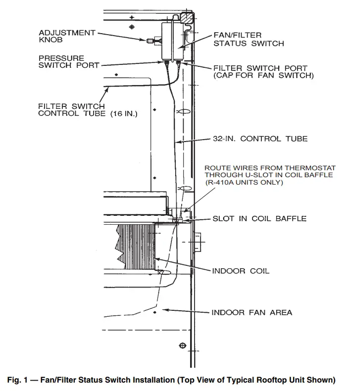
Attach the 32 in. plastic control tube to the pressure switch on the port nearest to the electrical connections. (See Fig. 1.) - Depending on the intended use:
a. Filter Switch
Attach the 16 in. plastic control tube to the pressure switch on the port nearest to the mounting bracket. (See Fig. 1.)
b. Fan Switch
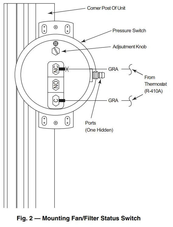
Attach the plastic cap to the pressure switch on the port nearest to the mounting bracket. (See Fig. 1.) - Attach the pressure switch assembly to the uppermost portion of the inner flange of the corner post with the 2 screws provided. (See Fig. 1.)
- Route the 32 in. control tube through the slot in the coil baffle next to the harness assembly.
The end of the control tube should be loose in the indoor fan area. (See Fig. 1.) - Filter Switch
Suspend the 16 in. control tube over the return air opening. (See Fig. 1.) - For units without DDC controls route and connect the digital indicator wires coming from the thermostat to the terminals on the pressure switch. (See Fig. 1 and 2.)
- For units with DDC controls, refer to the installation instructions for the DDC controls for proper wiring connection points for the Fan/Filter status switch.
- Return power to the unit.
- Depending on the intended use, configure the switch as follows:
a. Filter Switch
Place the unit in Fan Only mode. The unit return air filter should be clean or new. Using a flathead screwdriver, rotate the adjustment knob until the pressure switch closes. (See Fig. 1.) After the pressure switch closes, rotate the adjustment knob 1/4 turn in the same direction.
b. Fan Switch
Rotate the adjustment knob two full turns. - Reinstall the filter access panel reserved in Step 2.
 |  |
OPERATION
Filter Switch Operation
When the pressure switch is set up as a filter switch, the digital indicator light on the thermostat lights up when the filter is dirty and needs to be replaced. If direct digital controls are used, the filter status (CLEAN/DIRTY) is sent over the communications bus.
Fan Switch Operation
When the pressure switch is set up as a fan switch, the digital indicator light on the thermostat is lit when the indoor fan is operating. If the indoor fan is being told to operate by the thermostat and the indicator light is not lit, service the unit immediately. If direct digital controls are used, the indoor fan operation status (ON/OFF) is sent over the communications bus.
The manufacturer reserves the right to discontinue or change at any time, specifications or designs without notice and without incurring obligations.
Catalog No. 04-53480346-01
Printed in the U.S.A.
Form IIK-CRSTATUS01-02 Pg 4
5-22
Replaces: IIK-CRSTATUS01-01


