Dextra Halobay Installation
Halobay Installation
220-240V / 50-60Hz IP20
| Power | |
| L1 | Switched Live |
| E | Earth |
| N | Neutral |
| Emergency | |
| L2 | Unswitched Live |
| DA/AT3 | DALI Autotest |
| DA/AT3 | DALI Autotes |
| Dimming | |
| -/D1/DA | Analogue/DSI/DALI |
| +/D2/DA | Analogue/DSI/DAL |
| L3 | Switch Dim / Corridor Function |
WARNING: Luminaire must be earthed. Risk of electric shock from LED boards if operated with cover removed. Installation / operation outside of luminaires intended scope invalidates warranty. Suitable only for domestic / light industrial / industrial applications within the scope of EN55015. Tested to compliance with
BSEN 60598: specification for general requirements and tests. Must be installed by a suitably qualified person in accordance with all relevant legislation. Ambient operating temperature of 0°C to 25°C. If maximum operating temperature is exceeded luminaire will automatically dim / switch off. Terminal blocks are rated to 16A unless stated otherwise. The light source contained in this luminaire shall only be replaced by the manufacturer or his service agent or a similar qualified person. LUMINAIRES WITH EMERGENCY PACK:
When supply is isolated battery output terminals may be live if battery is connected. Isolate mains and battery before servicing. Emergency luminaires require unswitched live connection taken from same phase as switched supply. When unstitched supply is connected status indicator illuminates green, when unswitched supply is disconnected indicator extinguishes and luminaire operates in emergency mode. 24 hour charge period required before undertaking full discharge test. Emergency test sheets provided should be used to record all emergency tests. Batteries should be replaced when 3 hour duration is not met. Excessive switching of permanent live may result in premature battery failure. Battery electrolyte can be harmful to eyes / open wounds, do not puncture, if electrolyte touches skin / eyes flush with water. Do not incinerate batteries.


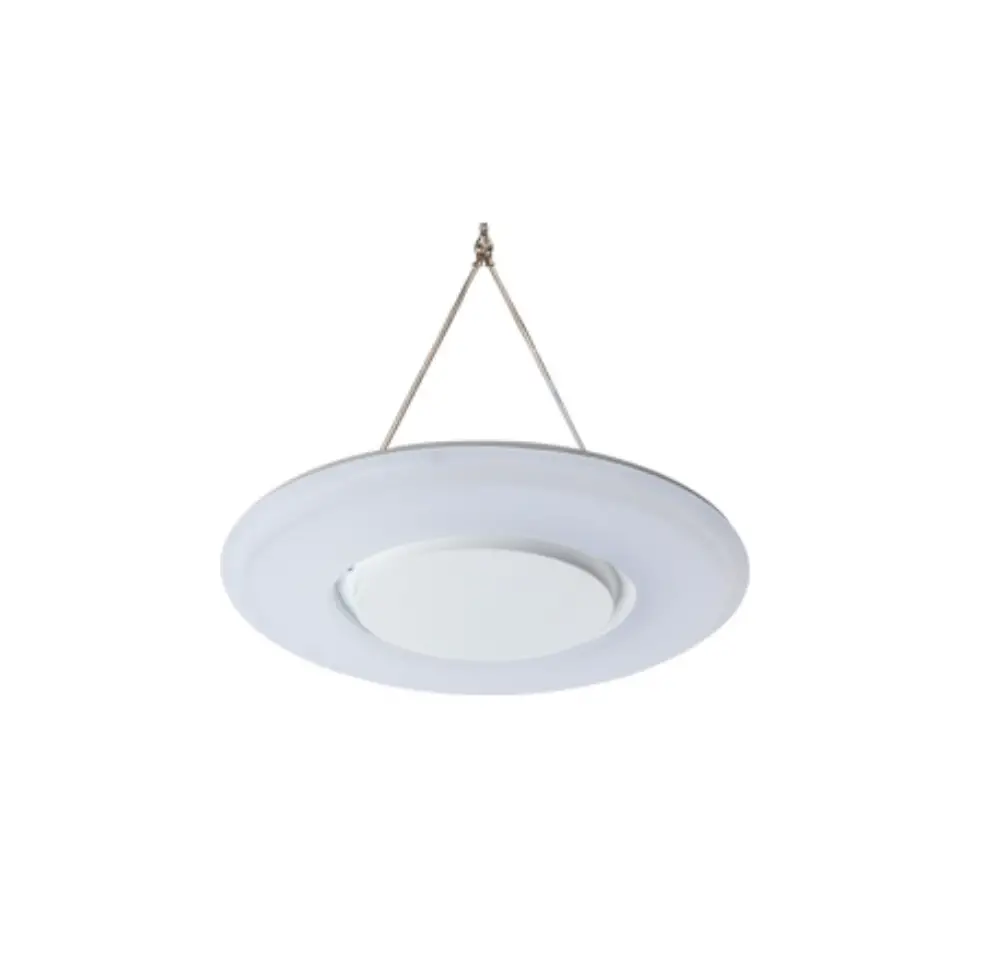
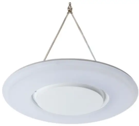
SUSPENDED INSTALLATION
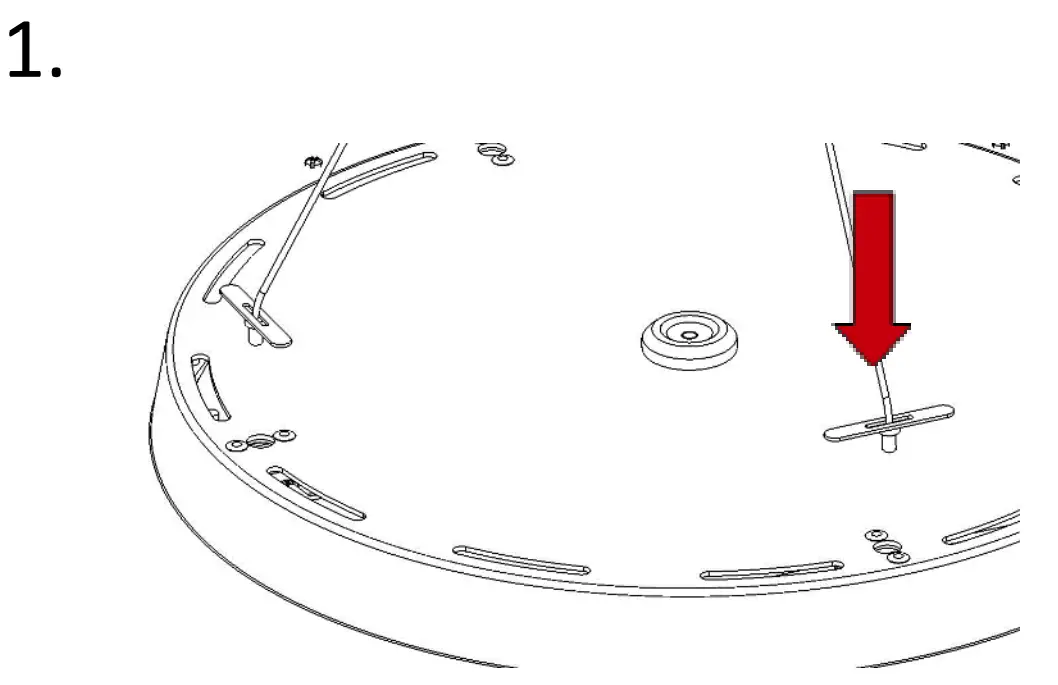
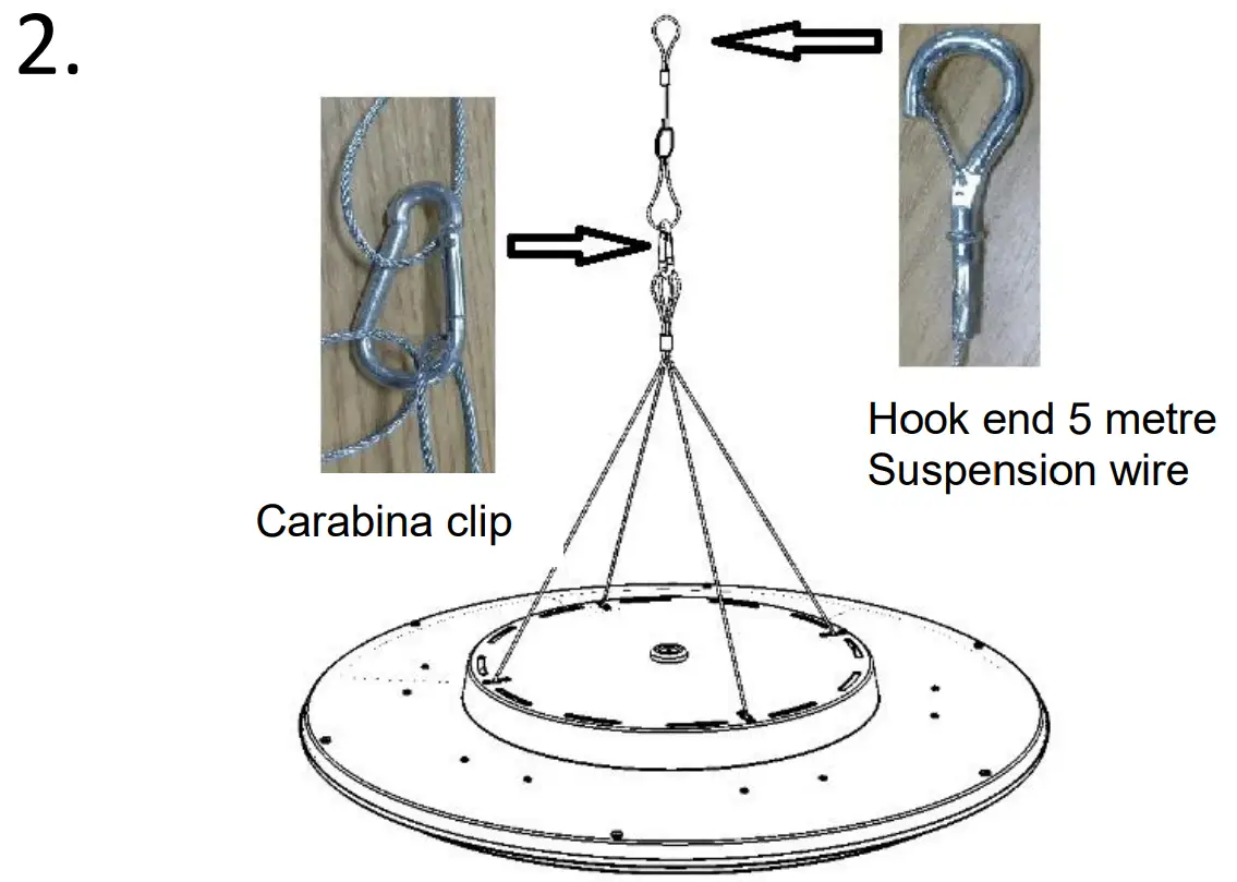
- Locate the 4no. suspension holes in the rear of the housing and feed the toggles through the holes provided.


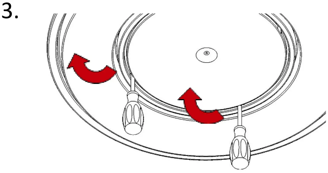
- Gently pull the screwdrivers towards the outside of the fitting to release the internal clips.

- Allow central cover to hang on tether to access the terminal connectors.

- Feed suitable mains cable through grommet in rear of housing.

- Wire mains cable into the respective terminals. All terminals are labelled for convenience. Ensure cable is clamped using the cable clamp provided.

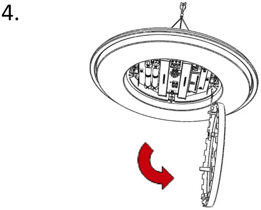
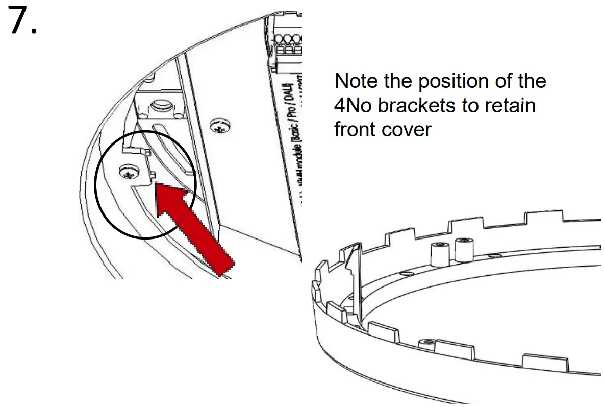
- Note the position of the 4No brackets to retain front cover

- Cover should click in to place.
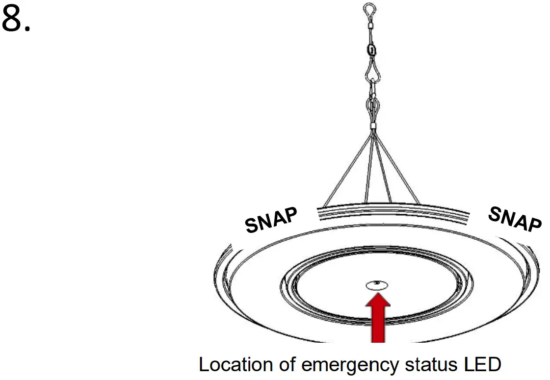
NOTE: If emergency, ensure indicator LED is secure in front cover.
SURFACE INSTALLATION
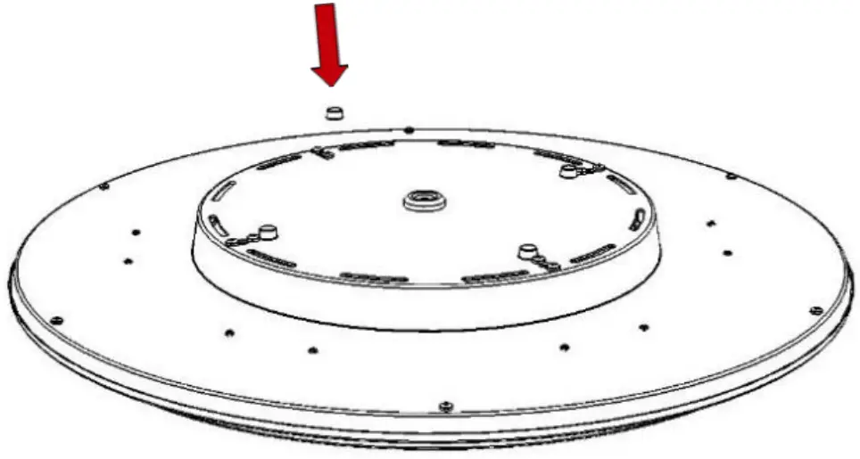
Prior to installation, apply 4No self-adhesive Stand-Off feet supplied – locate where shown, close to fixing holes.
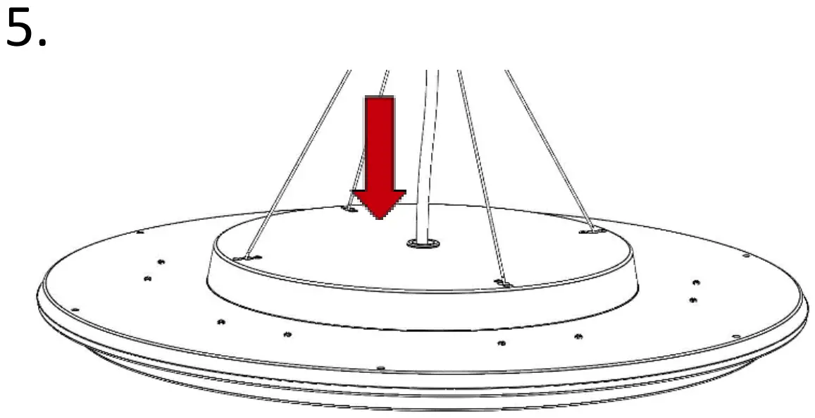
Mark out & prepare wall / ceiling. Feed cable through central hole & connect as image 5. Secure fitting with 4No screws (not supplied). Re-fit cover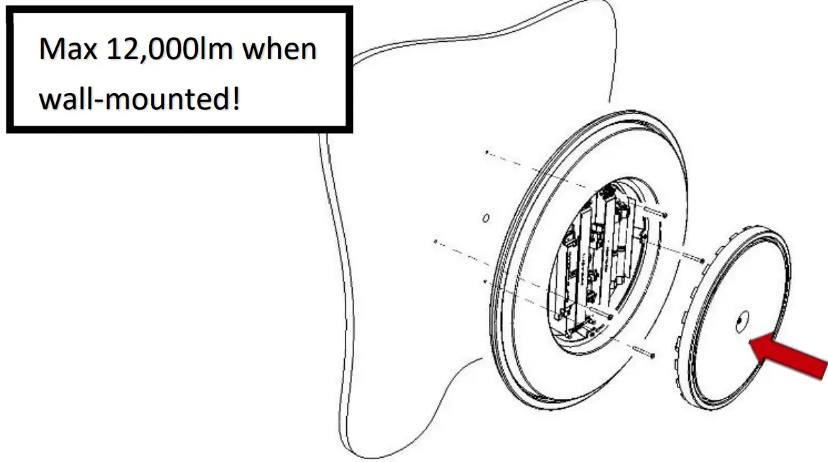
CEILING TILE INSTALLATION
Fit luminaire to tile – secure by placing rails over the back and screwing 4No self-tap screws (supplied) to tile edge.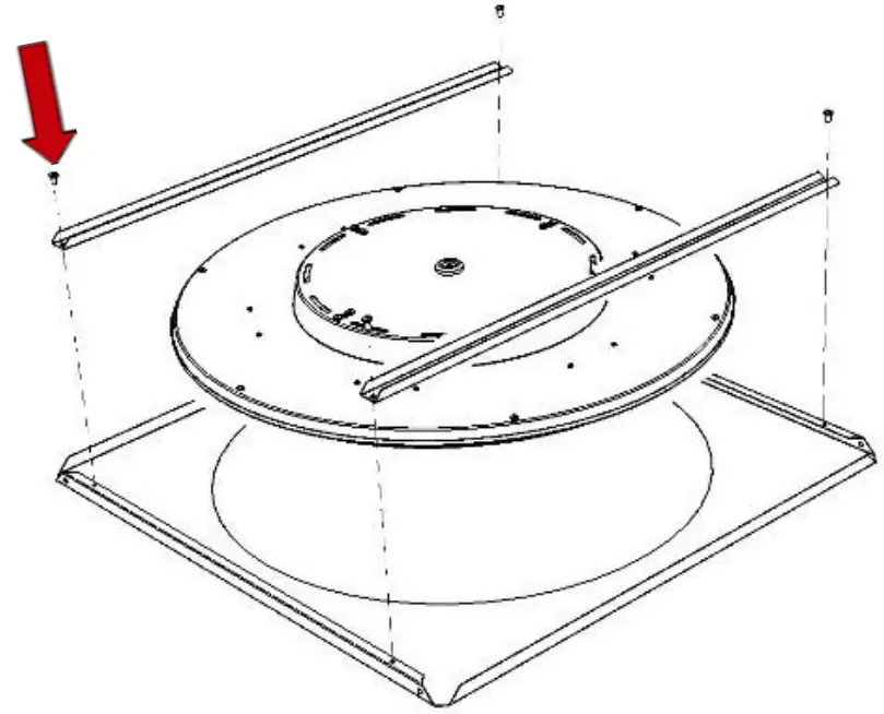
Once assembled, offer the complete fitting in to ceiling void and rest directly on to exposed T bars. Feed cable through central hole & connect as image 5. Re-fit cover.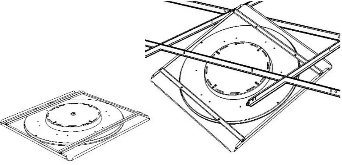
Maintenance
① Disconnect luminaire before undertaking any
maintenance or cleaning.
② Cleaning should be undertaken only on external parts of the
luminaire only using a slightly damp lint free cloth.
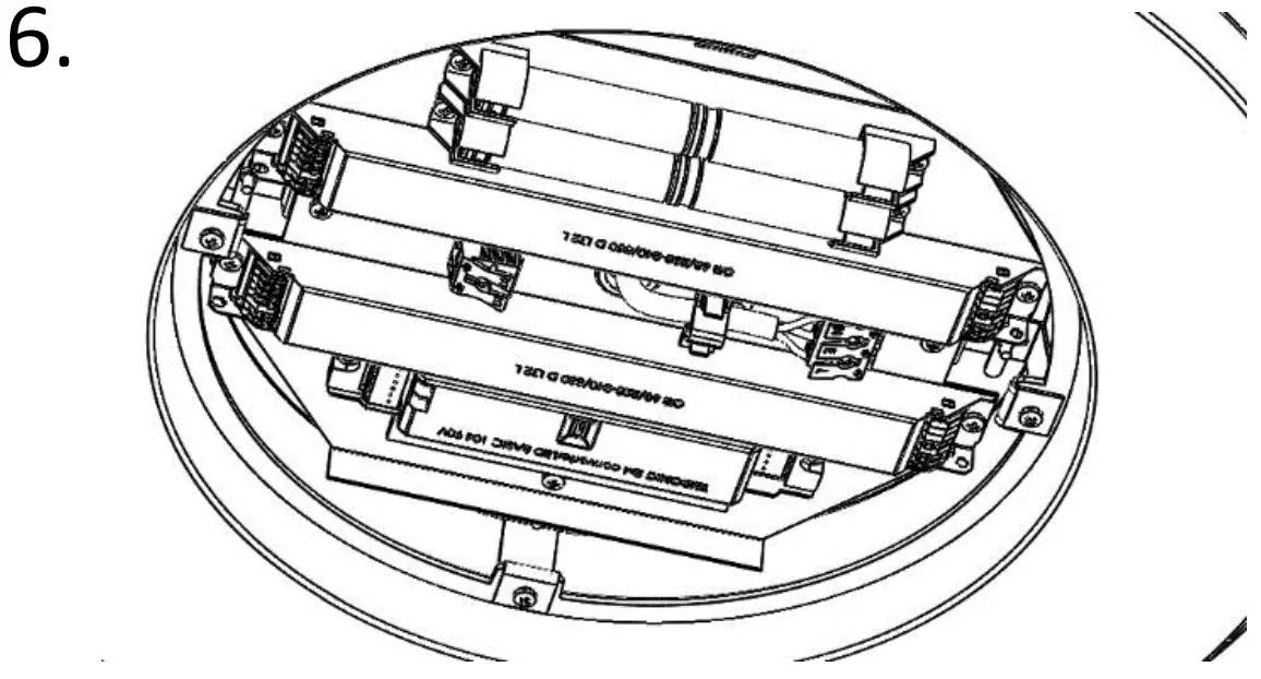
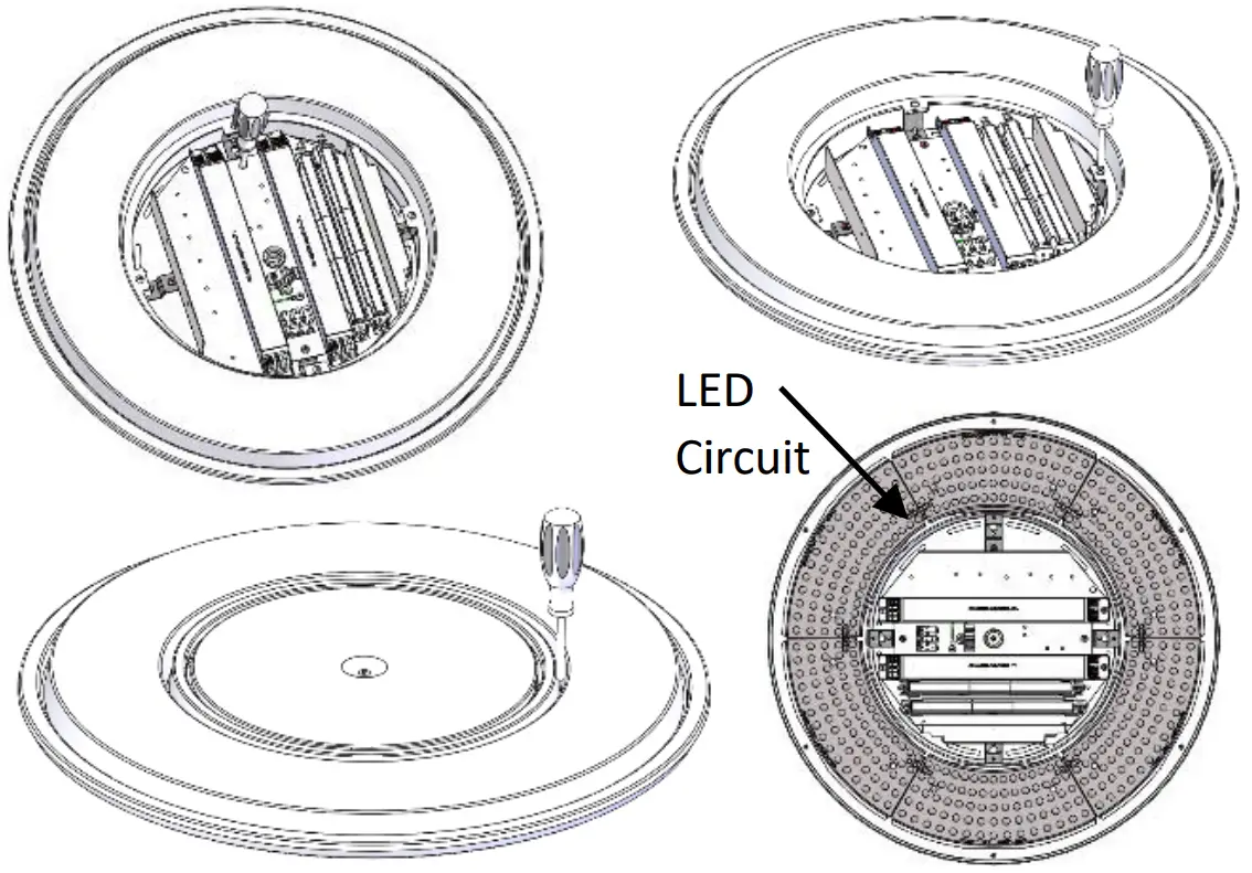
③ Using a flat head screwdriver release gear cover to access fitting.
④ Components, gear tray and diffuser are removable by using a pan pozi screwdriver.
⑤ Please contact Dextra for assistance with spare component supply


 Installation Guide")


