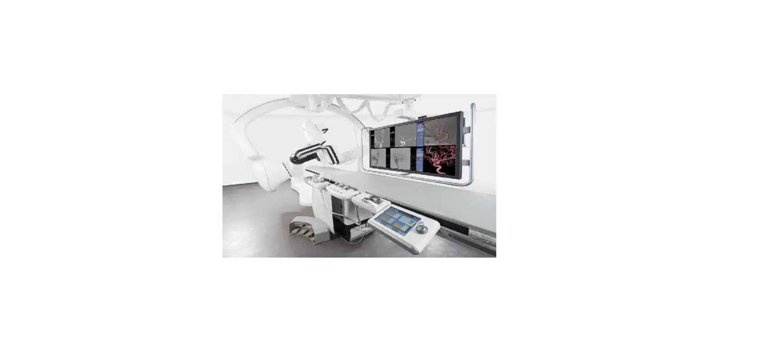
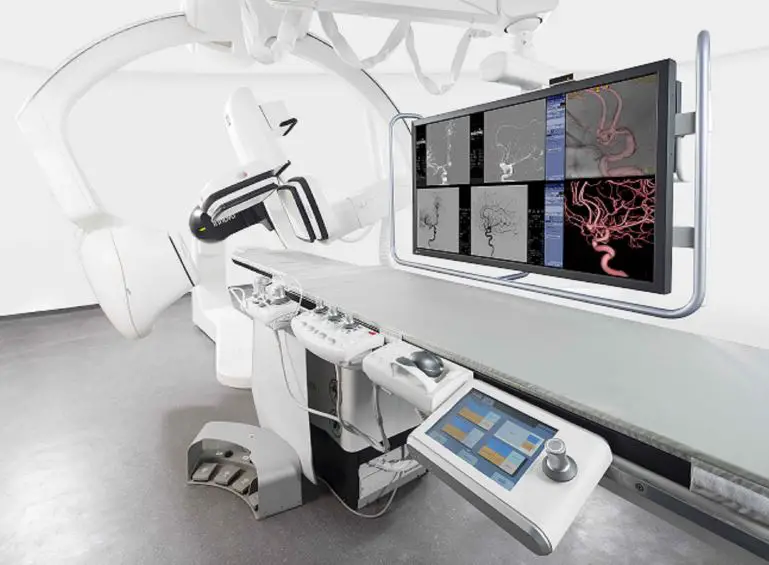
GE Healthcare INNOVA IGS 620-630 Interventional Neuroradiology
Product Information
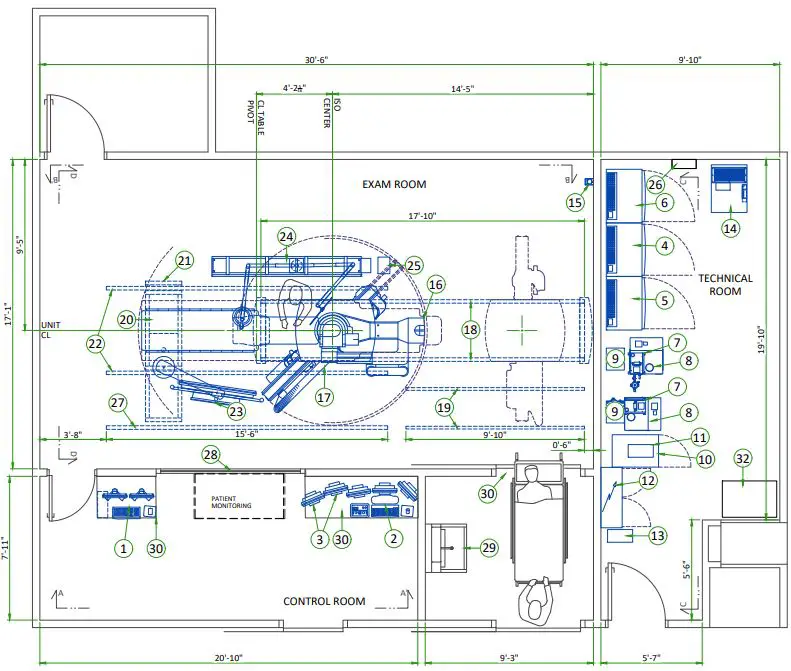
The product is the GE Healthcare Pre Installation manual for the INNOVA IGS 620-630 FINAL STUDY system. It is a set of drawings and specifications that provide guidance for site design and preparation before installing the GE Healthcare product. The manual includes various sections such as general notes, equipment layout, structural details, HVAC, electrical layout, power requirements, and interconnections. It also emphasizes the importance of referencing the Pre Installation manual to ensure complete documentation for site design and preparation.
Additionally, the manual mentions that GE Healthcare does not take responsibility for damages resulting from changes made by others to the drawings. It also advises against scaling from printed pdf files and states that GE accepts no responsibility or liability for defective work due to scaling from these drawings.
The manual is in A3 format with a scale of 1/4=1′-0. The file name is EN-VAS-TYP-IGS-6X0-WEB.DWG. There is also a reference to the PIM Manual 5694389-1-1EN, which provides further information and specifications for the product.
Product Usage Instructions
- Before starting the installation of the GE Healthcare INNOVA IGS 620-630 system, it is essential to refer to the Pre-Installation manual provided.
- Ensure that all necessary site design and preparation documentation is complete by following the guidelines in the manual.
- Familiarize yourself with the different sections of the manual, including general notes, equipment layout, structural details, HVAC, electrical layout, power requirements, and interconnections.
- Take note of the warnings and disclaimers mentioned in the manual, such as GE Healthcare not taking responsibility for changes made by others to the drawings and the potential issues with scaling from printed pdf files.
- Follow the specified format and scale of the drawings, which are in A3 size with a scale of 1/4=1′-0.
- Make sure to access the PIM Manual 5694389-1-1EN for additional information and specifications related to the product.
- Adhere to the customer responsibilities mentioned in the manual, such as ensuring room dimensions, ceiling support structure, cleanliness, cableways, and adequate illumination meet GE specifications.
- Install the system according to the guidelines provided in the manual, including the installation of countertops, vascular baseplates, and table baseplates if applicable.
- Follow any specific requirements mentioned in the manual for floor finish and protection for the IGS 730/740 models.
- If there are any uncertainties or questions regarding the installation process, contact a GE Healthcare representative for assistance.
DISCLAIMER
GENERAL SPECIFICATIONS
- GE is not responsible for the installation of developers and associated equipment, lighting, cassette trays and protective screens or derivatives not mentioned in the order.
- The final study contains recommendations for the location of GE equipment and associated devices, electrical wiring and room arrangements. When preparing the study, every effort has been made to consider every aspect of the actual equipment expected to be installed.
- The layout of the equipment offered by GE, the dimensions given for the premises, the details provided for the pre-installation work and electrical power supply are given according to the information noted during on-site study and the wishes expressed by the customer.
- The room dimensions used to create the equipment layout may originate from a previous layout and may not be accurate as they may not have been verified on site. GE cannot take any responsibility for errors due to lack of information.
- Dimensions apply to finished surfaces of the room.
- Actual configuration may differ from options presented in some typical views or tables.
- If this set of final drawings has been approved by the customer, any subsequent modification of the site must be subject to further investigation by GE about the feasibility of installing the equipment. Any reservations must be noted.
- The equipment layout indicates the placement and interconnection of the indicated equipment components.
- There may be local requirements that could impact the placement of these components. It remains the customer’s responsibility to ensure that the site and final equipment placement complies with all applicable local requirements.
- All work required to install GE equipment must be carried out in compliance with the building regulations and the safety standards of legal force in the country concerned.
- These drawings are not to be used for actual construction purposes. The company cannot take responsibility for any damage resulting therefrom.
CUSTOMER RESPONSIBILITIES
- It is the responsibility of the customer to prepare the site in accordance with the specifications stated in the final study. A detailed site readiness checklist is provided by GE. It is the responsibility of the customer to ensure all requirements are fulfilled and that the site conforms to all specifications defined in the checklist and final study. The GE Project Manager of Installation (PMI) will work in cooperation with the customer to follow up and ensure that actions in the checklist are complete, and if necessary, will aid in the rescheduling of the delivery and installation date.
- Prior to installation, a structrual engineer of record must ensure that the floor and ceiling is designed in such a way that the loads of the installed system can be securely borne and transferred. The layout of additional structural elements, dimensioning and the selection of appropriate installation methods are the sole responsibility of the structural engineer. Execution of load bearing structures supporting equipment on the ceiling, floor or walls are the customer’s responsibility.
RADIO-PROTECTION
- Suitable radiological protection must be determined by a qualified radiological physicist in conformation with local regulations. GE does not take responsibility for the specification or provision of radio-protection.
| THE UNDERSIGNED, HEREBY CERTIFIES THAT I HAVE READ AND APPROVED THE PLANS IN THIS DOCUMENT. | ||
| DATE | NAME | SIGNATURE |
GLOBAL SITE READINESS CHECKLIST (DI)
DOC1809666 Rev. 7
| Site Ready Checks at Installation |
| EHS Site Requirements |
| Overall access route to the scan room free from obstruction / high hazards. |
| Enough space to store tools, equipment, parts, install waste and the general area free from obstruction and trip hazards. |
| Enough necessary facilities for the GE employees available. |
| No 3rd parties working in the area that may affect the safety of the installation activity. |
| Area free from any chemical, gas, dust, welding fume exposure and has painting been completed and dry. |
| All emergency routes identified, signed and clear from obstruction. |
| Accessible single source lockable panel that LOTO can be applied to for GE equipment installation (MDP and/or PDU). |
| There are no other conditions or hazards that you have observed or have been made aware of by the customer or contractors on site. |
| Required for Mechanical Install start |
| Room dimensions, including ceiling height, for all Exam, Equipment/Technical & Control rooms meets GE specifications. |
| Ceiling support structure, if indicated on the GE drawing, is in the correct location and at the correct height according to the Original Equipment Manufacturer specifications. |
| Levelness and spacing has been measured, and is ready for the installation of any GE supplied components. |
| Overhead support Structure (unistrut) has been confirmed with customer/contractor to meet required GE provided criteria. |
| Finished ceiling is installed. If applicable ceiling tiles installed per PMI discretion. |
| Floor levelness/flatness is measured and within tolerance, and there are no visible defects per GEHC specifications. |
| Entry door threshold meets PIM requirement |
| Floor Strength and thickness have been discussed with customer/contractor and they have confirmed GE requirements are met. |
| Rooms that will contain equipment, including staging areas if applicable, are construction debris free. Precautions must be taken to prevent debris from entering rooms containing equipment. |
| Cable ways (floor/wall/ceiling/Access Flooring) are available for installation of GE cables are of correct length and diameter. |
| Cable ways routes per GE Final drawings and cable access openings areas installed at a time determined by GEHC PM. Surface floor duct can be installed at time of system installation. |
| Adequate room illumination installed and working. |
| Customer supplied countertops where GE equipment will be installed are in place. |
| Vascular baseplates preparation complete per GE requirements. |
| For IGS 730/740: Floor finish is according to the GE Specifications and protection is installed . Specifications for concrete substrate & Monopur 7 mm flooring have been met. Table baseplate installed and flush to the finished floor. |
| For IGS 730/740: Room Interventional Reference Point (RIRP) value has been defined with the customer. Either 1120mm, 1278 mm or 1508 mm. |
| Ensure that all third party suppliers are identified and have been informed about the project dates and how they need to proceed in accordance with their needs for interfacing to our equipment. |
| Required for Calibration start |
| HVAC systems Installed, and the site meets minimum environmental operational system requirements. |
| System power & grounding (PDB/MDP) is available as per GE specifications. |
| System power & grounding (PDB/MDP) is installed at point of final connection and ready to use. Lock Out Tag Out is available. |
| PMI to confirm all feeder wires and breaker are size appropriately. EPO installed if needed. |
| PMI to confirm with electrician all power and signal cables are well terminated ensuring there are no loose connections. |
| Network outlets installed. |
| Computer network available and working. |
| Lead doors and windows complete or scheduled to be installed. If applicable, radiation protection (shielding) finished & radioprotection regulatory approval for installation obtained. |
Note: The details shown here are only an extract from DOC1809666. For the complete document please contact your PMI.
INTERFERENCE SPECIFICATIONS
MAGNETIC INTERFERENCE SPECIFICATIONS
- Image intensifiers must be located in ambient static magnetic fields of less than 1 gauss to guarantee specified imaging performance.
- X-ray tubes must be located in ambient static magnetic fields of less than 10 gauss to guarantee specified performance.
- System electronics must be located in ambient static magnetic fields of less than 10 gauss to guarantee data integrity.
- Operators console equipment must be located in ambient static magnetic fields of less than 10 gauss to obtain specified geometric linearity.
CUSTOMER SITE READINESS REQUIREMENTS
- Any deviation from these drawings must be communicated in writing to and reviewed by your local GE healthcare installation project manager prior to making changes.
- Make arrangements for any rigging, special handling, or facility modifications that must be made to deliver the equipment to the installation site. If desired, your local GE healthcare installation project manager can supply a reference list of rigging contractors.
- New construction requires the following;
- Secure area for equipment,
- Power for drills and other test equipment,
- Capability for image analysis,
- Restrooms.
- Provide for refuse removal and disposal (e.g. crates, cartons, packing)
- For CT, MR, PET/CT, and SPECT systems it is required to minimize vibrations within the scan room. It is the customer’s responsibility to contract a vibration consultant/engineer to implement site design modifications to meet the GE vibration specification. Refer to the system preinstallation manual for vibration specifications.
ELECTROMAGNETIC INTERFERENCE
The system is suitable for use in the specified electromagnetic environment. The purchaser or user of the system should assure that it is used in an electromagnetic environment as described below:
| EMISSIONS | TEST COMPLIANCE | ELECTROMAGNETIC ENVIRONMENT |
|
Radio–Frequency Emissions CISPR11 | Group1 Class A limits | The system is suitable for use in all establishments other than domestic and those directly connected to the low voltage power supply network that supplies buildings used for domestic purposes. |
| Group1 Class A limits | The system uses RF energy only for its internal function. Therefore, the RF emission is very low and not likely to cause any interference in nearby electronic equipment. | |
| Harmonic emissions IEC 61000–3–2 | Not applicable | The system is suitable for use only in establishments not directly connected to a public low voltage power supply network. |
| Voltage fluctuations/ flicker emissions IEC 61000–3–3 | Not applicable | The system is suitable for use only in establishments not directly connected to a public low voltage power supply network. |
| A | GE Supplied | D | Available from GE | |||||
| B | GE Supplied/contractor installed | E | Equipment existing in room | |||||
| C | Customer/contractor supplied and installed | * | Item to be reinstalled from another site | |||||
| MAX | MAX | |||||||
| BY | ITEM | DESCRIPTION | HEAT OUTPUT | WEIGHT (lbs) | HEAT OUTPUT | WEIGHT (kg) | ||
| (btu) | (W) | |||||||
| D | 1 | Advantage workstation | 3412 | 22 | 1000 | 10 | ||
| A | 2 | Operator console | 1405 | 19.6 | 410 | 9 | ||
| D | 3 | Reference monitor | 1706 | 18 | 500 | 8 | ||
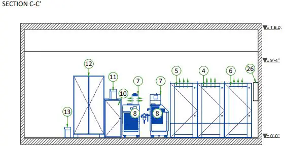
| A | 4 | C1 Frontal Cabinet | 5435 | 809 | 1590 | 367 | ||
| A | 5 | C1 Lateral Cabinet | 3969 | 692 | 1160 | 314 | ||
| A | 6 | C2 Cabinet | 6171 | 578 | 1810 | 262 | ||
| A | 7 | Detector conditioner | 709 | 32 | 210 | 14.5 | ||
| A | 8 | COOLIX 4100 water chiller | 21496 | 265 | 6300 | 120 | ||
| A | 9 | Chiller Autotransformer | 709 | 66 | 210 | 30 | ||
| A | 10 | Large Display Cabinet | 3412 | 254 | 1000 | 115 | ||
| A | 11 | 3kVA LDM UPS | 1257 | 79 | 370 | 36 | ||
| B/D | 12 | Power Distribution Box | 2216 | 859 | 650 | 389.5 | ||
| A | 13 | 3kVA PDB UPS | 1257 | 79 | 370 | 36 | ||
| D | 14 | 20kVA Fluoro UPS UL | 4720 | 1065 | 1380 | 541 | ||
| A | 15 | Xray buzzer | – | 1 | – | 0.5 | ||
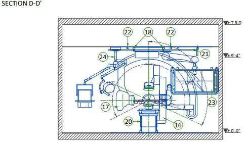
| A | 16 | LC gantry | 5517 | 1556 | 1620 | 705 | ||
| A | 17 | LP Gantry | 5517 | 1757 | 1620 | 797 | ||
| A | 18 | Longitudinal stationary rail for LP | – | 68 | – | 31 | ||
| Gantry | ||||||||
| B | 19 | Cable drape rail for LP Gantry | – | – | – | – | ||
| A | 20 | OMEGA V patient table | 614 | 1664 | 180 | 754.5 | ||
| A | 21 | Monitor suspension short bridge | – | – | – | – | ||
| A | 22 | Longitudinal stationary rail | – | 68 | – | 31 | ||
| D | 23 | Large Display Monitor with two backup monitors | – | 880 | – | 399 | ||
| D | 24 | Mavig rad shield and LED lamp with 2.5m ceiling track | – | 143 | – | 65 | ||
| D | 25 | External Transformer for LED Surgical lamp | – | 6 | – | 3 | ||
| Circuit breaker or equivalent with LOTO must be installed in the mains line to the PDB | ||||||||
| C | 26 | this device must be compatible with the power input specifications of the system. the | ||||||
| customer is responsible for procurement, delivery, and installation. | ||||||||
| C | 27 | Cable drape rail. | ||||||
| C | 28 | Control wall to ceiling with lead glass viewing window. | ||||||
| C | 29 | Scrub sink | ||||||
| C | 30 | Countertop for equipment- provide grommeted openings as required to route cables | ||||||
| C | 31 | Minimum door opening for equipment delivery is 44 in. w x 83 in. h [1118mm x 2108mm], contingent on a 96 in. [2438mm] Corridor width | ||||||
| C | 32 | Storage Cabinet | ||||||
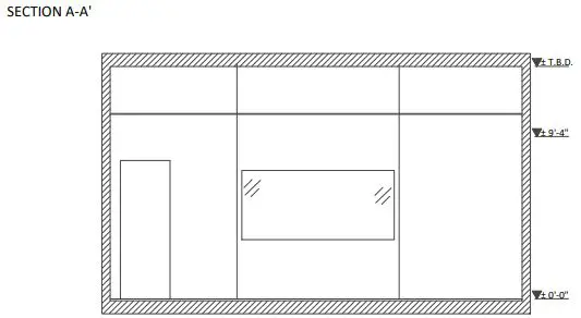
| EXAM ROOM HEIGHT | ||||||||
| Required | Required | |||||||
| FINISHED FLOOR-TO-FALSE CEILING | 2845mm | 9′-4″ +/- 0.2″ | ||||||
| Door openings: Exam room min 1160 [50 in], Technical room min 800 [36 in], rec 1000 [40 in] | ||||||||
For Accessory Sales: (866) 281-7545 Options 1, 2, 1, 2 or mail to: [email protected]
CONTROL ROOM VIEW
EXAM ROOM VIEW
TECHNICAL ROOM VIEW
TECHNICAL ROOM VIEW
GANTRY
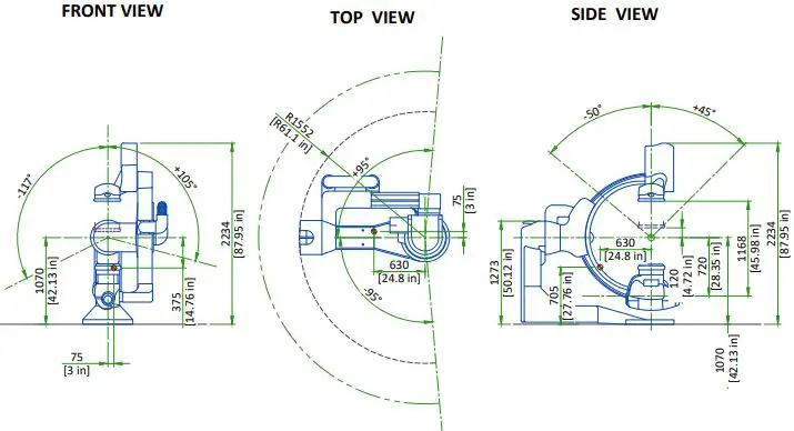
 Center of Gravity
- SCALE 1:50
LATERAL POSITIONER
OMEGA V PATIENT TABLE
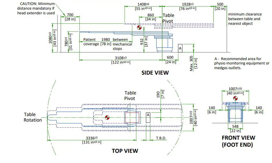
- Center of Gravity
- Scale 1:20
INNOVA CABINETS
| CENTER OF GRAVITY | ||||||
| CABINET | C1 (AP) | C1 (LAT) | C2 | |||
| DIMENSION | mm | in | mm | in | mm | in |
| A | 452 | 17.7 | 506 | 19.9 | 400 | 15.7 |
| B | 283 | 11.1 | 338 | 13.3 | 325 | 12.8 |
| C | 904 | 35.5 | 839 | 33.0 | 948 | 37.3 |
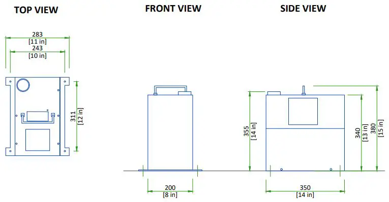
LARGE DISPLAY CABINET
DIGITAL ENERGY SG SERIES 10-20kVA UPS
3kVA UPS
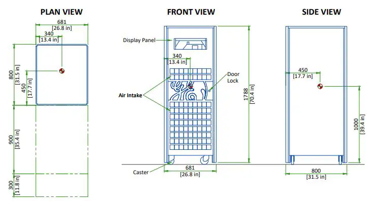
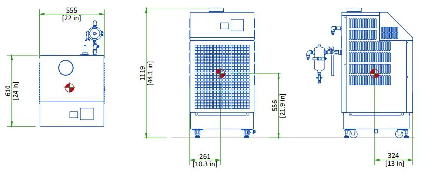
X-RAY TUBE CHILLER
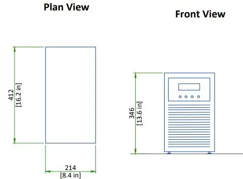
COOLIX AUTOTRANSFORMER
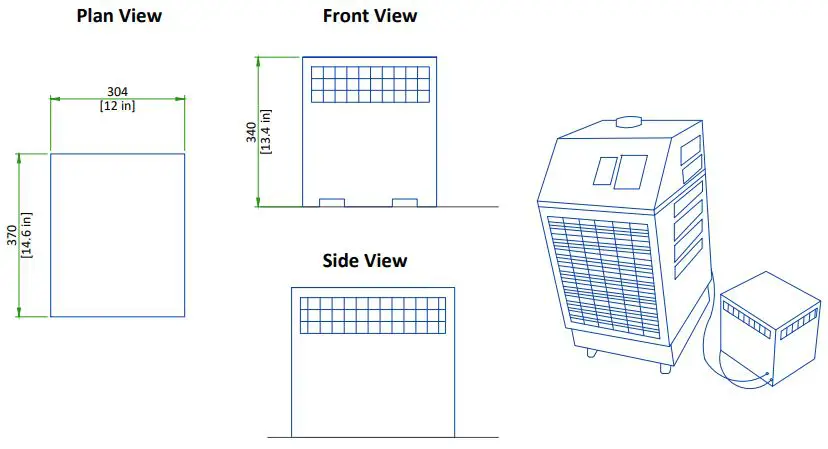
DETECTOR CONDITIONER
DELIVERY
The customer should
- Provide an area adjacent to the vascular suite for delivery and unloading of the GE equipment.
- Ensure that the dimensions of all doors, corridors, ceiling heights are sufficient to accommodate the movement of GE equipment from the delivery area into the definitive installation room.
- Ensure that access routes for equipment will accommodate the weights of the equipment and any transportation, lifting and rigging equipment.
- Ensure that all necessary arrangements for stopping and unloading on public or private property not belonging to the customer have been made.
| DIMENSIONS OF DELIVERY WITH DOLLY TRANSPORT EQUIPMENT | |||||
| EQUIPMENT | DIMENSIONS | WEIGHT | |||
| LC GANTRY | LENGTH | 2820 mm | 111 in | 1060 kg | 2340 lbs |
| WIDTH | 1230 mm | 48.4 in | |||
| HEIGHT | 2000 mm | 79 in | |||
| LP GANTRY | LENGTH | 2790 mm | 109.8 in | 1225 kg | 2700 lbs |
| WIDTH | 1135 mm | 44.7 in | |||
| HEIGHT | 2152 mm | 84.7 in | |||
| LP RAILS (BOX) | LENGTH | 6070 mm | 239 in | 95 kg | 209 lbs |
| WIDTH | 260 mm | 10 in | |||
| HEIGHT | 300 mm | 11.8 in | |||
SHIPPING DOLLY FOR LP GANTRY
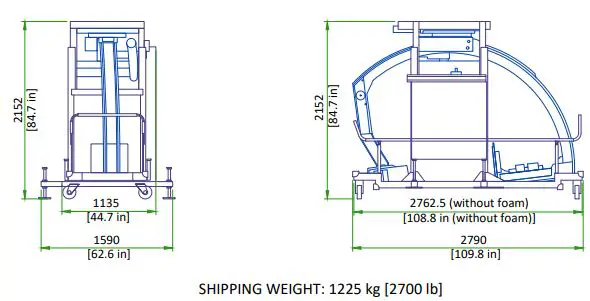
- The minimum door width needed (to accommodate the IGS Lateral shipping dolly) is 1135 mm [44.7 in] with the dolly stabilizers retracted.
SHIPPING DOLLY FOR LC GANTRY
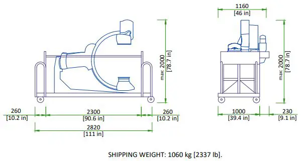
- Both ends of the dolly can be removed which will shorten the LC gantry dolly to 2300 mm [90 in], also the right and left top handles can be removed which will make the width 1160 mm [46 in].
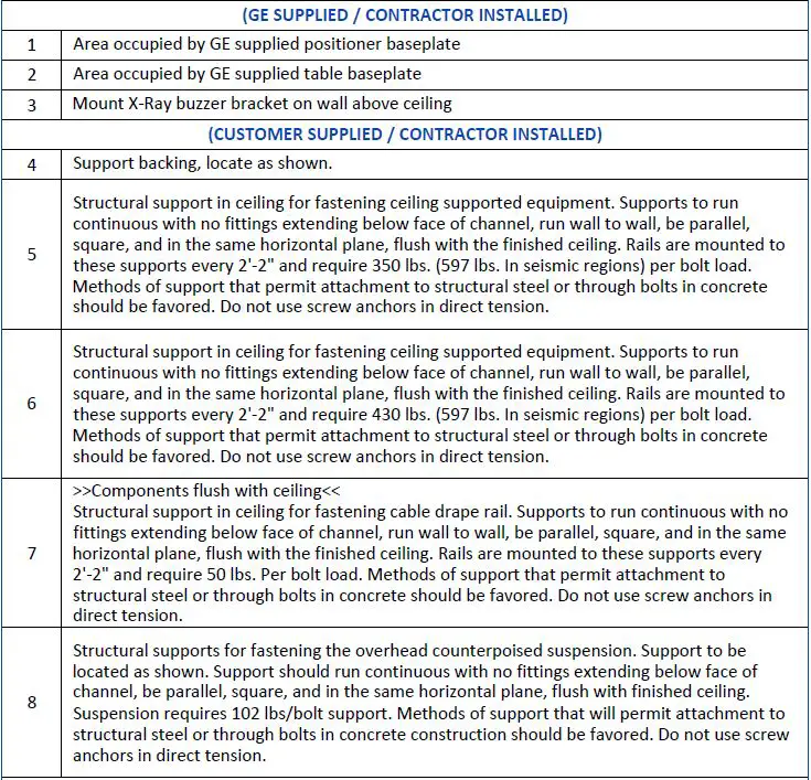
STRUCTURAL NOTES
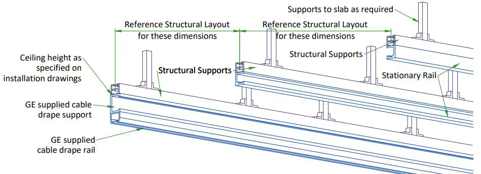
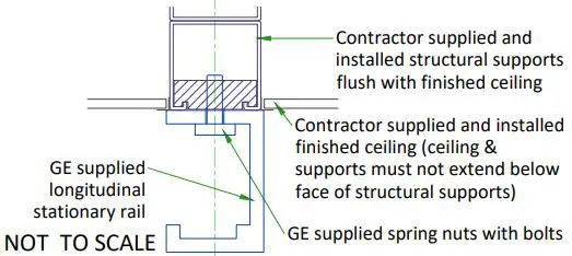
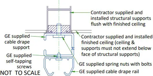
- All steel work and parts necessary to support ceiling-mounted tube hanger or other equipment are to be supplied by the customer or his contractors. The unistrut or equivalent structure should run continuous with no fittings extending below face of unistrut channel, run wall to wall, be parallel, square and in the same horizontal plane flush with finished ceiling. The system is to be cross braced vertically, horizontally and diagonally to allow no movement and a maximum of 1,58mm(1/16″) deflection. (10) 12,7mm (1/2″) dia. X 38,1mm (1 1/2″) long bolts with unistrut 12,7mm (1/2″) nuts with springs are to be provided by customer or his contractors for each stationary and auxillary support rail. Closure strips shall be provided for areas of unistrut exposed and without mounting units.
- Methods of support for the steelwork that will permit attachment to structural steel or through bolts in concrete construction should be favored. Do not use concrete or masonry anchors in direct tension.
- All units that are wall mounted or wall supported are to be provided with supports where necessary. Wall supports are to be supplied and installed by the customer or his contractors. See plan and detail sheets for suggested locations and mounting hole locations.
- All ceiling mounted fixtures, air vents, sprinklers, etc. To be flush mounted, or shall not extend more than 6,35mm (1/4″) below the finished ceiling.
- Control walls with tube hanger passage above shall be constructed to 2130mm (7′-0″) high.
- Floor slabs on which equipment is to be installed must be level to 3,17mm (1/8″) in 3050mm (10′-0″)
- Minimum floor thickness of 203mm (8″).
- Dimensions are to finished surfaces of room.
- The customers contractor must provide all penetrations in post-tension floors.
- The customers contractor must provide and install any non-standard anchoring. Documents for standard anchoring methods are included with GE equipment drawings for geographic areas that require such documentation.
- Customers’ contractor must provide and install hardware for “through the floor” anchoring and/or any bracing under access floors. This contractor must also provide floor drilling that cannot be completed because of an obstruction encountered while drilling by the GE installer such as rebar etc.
- It is the customer’s responsibility to perform any floor or wall penetrations that may be required. The customer is also responsible for ensuring that no subsurface utilities (e.g., electrical or any other form of wiring, conduits, piping, duct work or structural supports (i.e. post tension cables or rebar)) will interfere or come in contact with subsurface penetration operations (e.g. drilling and installation of anchors/screws) performed during the installation process. To ensure worker safety, GE installers will perform surface penetration operations only after the customer’s validation and completion of the “GE surface penetration permit”
IF ACCESS IS NOT READILY AVAILABLE IT IS RECOMMENDED TO PROVIDE A TRAPDOOR IN THE CEILING TO ALLOW SERVICE ACCESS FOR CABLE MANAGEMENT.
STRUCTURAL LAYOUT ITEM LIST
LC GANTRY AND TABLE ANCHORING WITH NO BASEPLATE
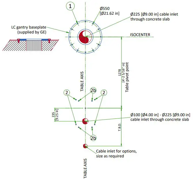
- 1: LC baseplate mounting location: 12 bolts Pullout strength on each bolt 736 daN
- M20 Through-Bolts recommended (supplied by GE) Alternates:
- M16 Mechanical anchors (supplied by GE)
- Chemical anchors (not supplied by GE): HILTIHVU adhesive capsule + HAS Anchor rod
- 2: Table mounting location: 4 bolts required Pullout strength on each bolt 4432 daN
- M20 Through-Bolts recommended (supplied by GE) Alternates:
- M16 Mechanical anchors (supplied by GE)
- Chemical anchors (not supplied by GE): HILTIHVU adhesive capsule + HAS Anchor rod
- 2b: Alternate bolt holes for seismic zones 1 and 2
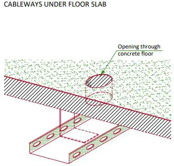
FLOOR REQUIREMENTS AND CABLE MANAGEMENT
FLOOR REQUIREMENTS
- The maximum pullout force per GE supplied anchor was calculated assuming :
- A concrete compression strength of 17.24 MPa at 28 days (which is the minimum required compression stength).
- Anchors installed to the required hole depth of 165.1 mm [6.5 in] minimum.
- Center of anchor hole to concrete edge distance 79.4 mm [3.1 in].
- Make sure to obtain data on compression strength of the concrete before using floor anchors.
- The floor slab on which the equipment is to be installed must be flat and level (1 mm [0.04 in]/1 m [40 in] where equipment is installed and 5 mm [0.2 in]/2 m [79 in] general levelness).
- Anchoring to the floor is intended to the structural elements and not to common screed.
- Do not glue the floor covering in the gantry zone.
JUNCTION BOX BELOW FLOOR
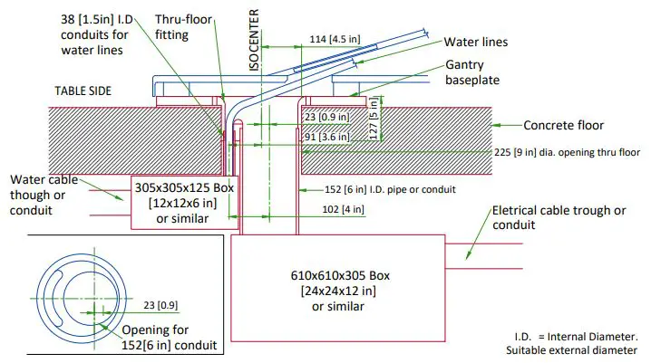
NOTE: PIPE, JUNCTION BOX AND DUCT OR CONDUIT ARE TO BE SUPPLIED AND IS TO BE INSTALLED BY CUSTOMER OR CUSTOMER’S CONTRACTOR.
XT RADIOGRAPHIC SUSPENSION, INBOARD MOUNTING
Structural Support system is not supplied or installed by GE Healthcare
DETAIL 1
DETAIL 2
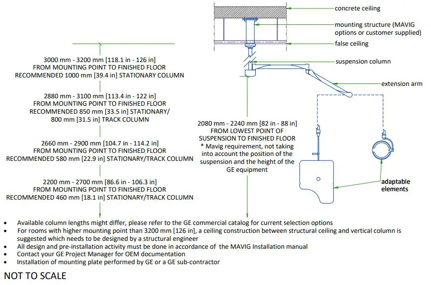
MAVIG SUSPENSION MOUNTING METHOD
- Weight up to: 94 kg [207 lb] (75 kg [165 lb] system + 19 kg [42 lb] track)
- The required factor of safety is “4” for attaching to Unistrut or equivalent rails and “6” for attaching to the concrete ceiling.
CONSULT MAVIG INSTALLATION MANUAL REV: POR03001 TO DESIGN AND MOUNT THE CEILING SUPPORT.
SUSPENSION COLUMN LENGTHS AND INSTALLATION DETAILS
MONITOR SUSPENSION RAIL MOUNTING SPECIFICATIONS
CEILING SUSPENSION DISCLAIMER
Safety and precautionary comments
Only qualified, licensed technicians can perform electrical connections, installation, removal and repair. It is strongly recommended that at least two persons perform the installation.
Installing the system: Prior to installation, a structural engineer must confirm that the mounting structure is strong enough to provide proper support for the entire system and any attached end devices. Installation must be completed according to local building codes. Determination of required installation hardware and torque values for installation of the ceiling column and ceiling track is the sole responsibility of the structural engineer. Ceiling mounted systems must be installed properly. Failure to follow the instructions provided may lead to a potentially dangerous and unstable condition of the system.
GE and/or MAVIG is not responsible for unauthorized modifications made to the system or use of the system for unintended purposes. GE and/or MAVIG cannot be held liable for improper operation and modifications. Since improper modifications may impair proper operation, safety or reliability of the system, product modifications require written authorization from MAVIG. Under GE responsibility or under Customer responsibility, for all pre-installations, whatever is the supporting structure (bridge, chair, Unistrut channel, other channels, direct anchorage in concrete, transversal beam, etc. …) a certificate must be obtained from a structural engineer. This certificate shall include the definition of fasteners and of their tightening torque, especially for the non-standard cases described in MAVIG PIM and for which the standard anchoring/screws delivered with product shall not be used but shall be defined (and implemented in most cases) by the structural company.
WARNING: It is prohibited to alter the length of the ceiling column or remove any securing screws.
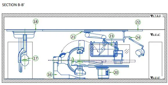
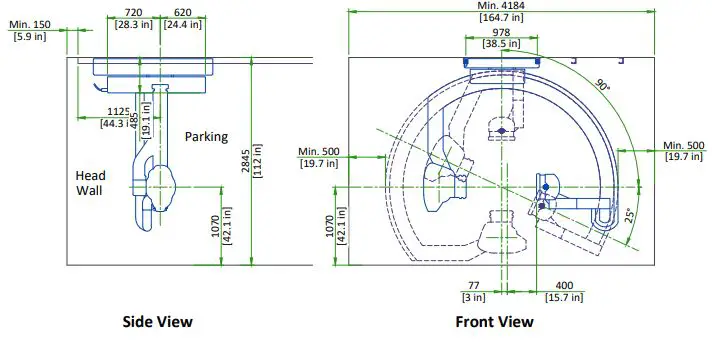
LOCATION OF LATERAL POSITIONER AND MONITOR SUSPENSION RAILS- SECTION
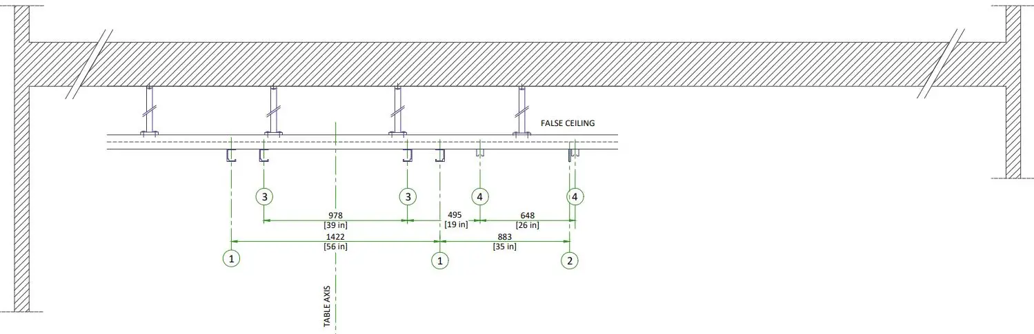
| MONITORS CENTERED | |
| 1 | Monitor suspension axis |
| 2 | Monitor cable suspension axis |
| 3 | Lateral positioner rail axis |
| 4 | Lateral positioner cable suspension axis |
| Note: no mounting hardware can protrude below the finished ceiling height (top surface of lateral positioner stationary rails), such as Unistrut mounting bolts, support brackets, sprinklers, air vents etc. in between LP stationary rails | |
LATERAL POSITIONER RAIL MOUNTING SPECIFICATIONS
WARNING: STRUCTURE SHOULD NOT ALLOW VIBRATIONS TRANSMISSION EQUAL OR LOWER THAN 10Hz
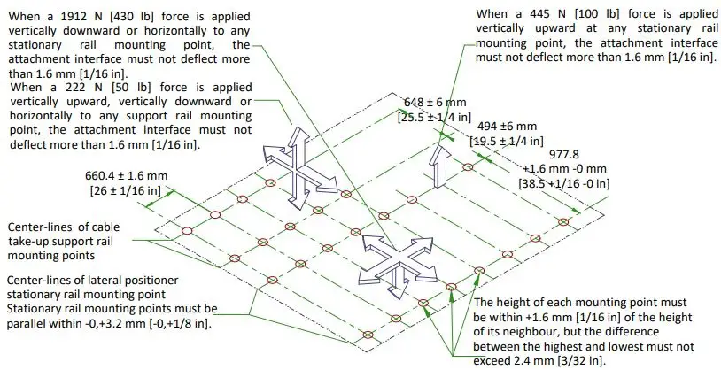
CAUTION
- The maximum load per bolt will not exceed 1912 N [430 lb].
- Each bolt must not “pull out” otherwise fail under a vertically downward “dead” load of 7633 N [1717 lb].
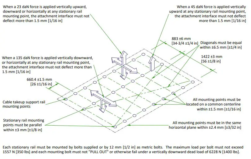
OTS SUSPENSION RAILS MOUNTING SPECIFICATIONS
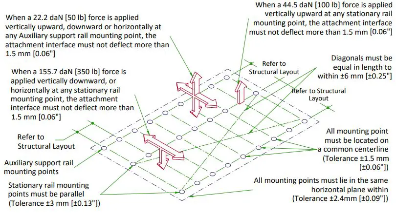
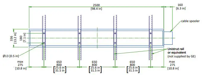
Distance between holes axis 660.4 mm [26 in], Maximum load per screw is 155.7 daN [350 lb], however each mounting screw must not “PULL OUT” or otherwise fail under a vertically downward dead load of 622.8 daN [1400 lb]. Bolts for mounting stationary rails on structural supports supplied by GE (1/2″ – 13 headed bolts)
TEMPERATURE AND HUMIDITY SPECIFICATIONS
IN-USE CONDITIONS
| EXAM ROOM | CONTROL ROOM | TECHNICAL ROOM | |||||||
| Temperature | Min | Recommended | Max | Min | Recommended | Max | Min | Recommended | Max |
| 15 °C [59 °F] | 22 °C [72 °F] | 32 °C [90 °F] | 15 °C [59 °F] | 22 °C [72 °F] | 35 °C [95 °F] | 10 °C [50 °F] | 18 °C [64 °F] | 32 °C [90 °F] | |
| Temperature gradient | ≤ 10 °C/h [50 °F/h] | ≤ 10°C/h [50 °F/h] | ≤ 10 °C/h [50 °F/h] | ||||||
| Relative humidity (1) | 30% to 70% | 30% to 75% | 30% to 75% | ||||||
| Humidity gradient | ≤ 10%/h | ≤ 10%/h | ≤ 10%/h | ||||||
STORAGE CONDITIONS
| Temperature | +10 °C [50 °F] to +40 °C [104 °F] |
| Relative humidity (1) | 10% to 80% |
| Material should not be stored for more than 90 days. | |
- (1) Non-condensing
AIR RENEWAL
- According to local standards.
NOTE: In case of using air conditioning systems that have a risk of water leakage it is recommended not to install it above electric equipment or to take measures to protect the equipment from dropping water.
HEAT DISSIPATION
| ROOM | DESCRIPTION | HEAT DISSIPATION (kW) | HEAT DISSIPATION (BTU/hr) | ||||
| STAND BY | AVERAGE* | MAX | STAND BY | AVERAGE* | MAX | ||
|
Examination room | LC Gantry / LP Gantry | 0.61 | 1.21 | 1.62 | 2076 | 4128 | 5517 |
| Patient table | |||||||
| Large Display Monitor (LDM) | 0.50 | 0.50 | 0.50 | 1706 | 1706 | 1706 | |
| Typical injector | 0.09 | 0.09 | 0.09 | 320 | 320 | 320 | |
| TOTAL | 1.20 | 1.80 | 2.21 | 4102 | 6154 | 7543 | |
| DL user area with 1 TFT monitor | 0.16 | 0.16 | 0.16 | 546 | 546 | 546 | |
| Advantage Workstation (AW) | – | – | 1.00 | – | – | 3412 | |
| Additional LCD monitor(s) | 0.12 | 0.12 | 0.12 | 409 | 409 | 409 | |
| TOTAL | 0.28 | 0.28 | 1.28 | 79′-7″ | 79′-7″ | 363′-11″ | |
|
Technical room | C1 Frontal cabinet | 0.71 | 1.29 | 1.59 | 2421 | 4412 | 5435 |
| C1 Lateral cabinet | 0.31 | 0.86 | 1.16 | 1057 | 2946 | 3969 | |
| C2 Cabinet | 0.29 | 1.34 | 1.81 | 989 | 4571 | 6171 | |
| Coolix 4100 chiller Frontal & Lateral @ 60Hz (x2) | 4.64 | 6.88 | 12.60 | 15832 | 23474 | 42991 | |
| Chiller autotransformer @60Hz(x2) | 0.12 | 0.14 | 0.18 | 410 | 478 | 614 | |
| Detector conditioner (x2) | 0.42 | 0.42 | 0.42 | 1418 | 1418 | 1418 | |
| Power Distribution Box (PDB) | 0.6 | 0.65 | 0.65 | 2216 | 2216 | 2216 | |
| UPS 3 KVA | 0.37 | 0.37 | 0.37 | 1257 | 1257 | 1257 | |
| UPS 3 KVA for LDM | 0.37 | 0.37 | 0.37 | 1257 | 1257 | 1257 | |
| LD cabinet | 1.00 | 1.00 | 1.00 | 3412 | 3412 | 3412 | |
| Fluoro UPS UL | 1.38 | 1.38 | 1.38 | 4720 | 4720 | 4720 | |
| TOTAL | 10.21 | 14.70 | 21.53 | 2915′-9″ | 4180′-1″ | 6121′-8″ | |
WARNING
- The list contains only the principal components of the system and doesn’t contain any non-GE supplied equipment.
- This average corrisponds to 11 cases in 10 hours.
ELECTRICAL NOTES
All wires specified shall be copper stranded, flexible, thermo-plastic, color coded, cut 10 foot long at outlet boxes, duct termination points or stubbed conduit ends. All conductors, power, signal and ground, must be run in a conduit or duct system. Electrical contractor shall ring out and tag all wires at both ends. Wire runs must be continuous copper stranded and free from splices.
- Aluminum or solid wires are not allowed.
- Wire sizes given are for use of equipment. Larger sizes may be required by local codes.
- It is recommended that all wires be color coded, as required in accordance with national and local electrical codes.
- Conduit sizes shall be verified by the architect, electrical engineer or contractor, in accordance with local or national codes.
- Convenience outlets are not illustrated. Their number and location are to be specified by others. Locate at least one convenience outlet close to the system control, the power distritbution unit and one on each wall of the procedure room. Use hospital approved outlet or equivalent.
- General room illumination is not illustrated. Caution should be taken to avoid excessive heat from overhead spotlights. Damage can occur to ceiling mounting components and wiring if high wattage bulbs are used. Recommend low wattage bulbs no higher than 75 watts and use dimmer controls (except MR). Do not mount lights directly above areas where ceiling mounted accessories will be parked.
- Routing of cable ductwork, conduits, etc., must run direct as possible otherwise may result in the need for greater than standard cable lengths (refer to the interconnection diagram for maximum usable lengths point to point).
- Conduit turns to have large, sweeping bends with minimum radius in accordance with national and local electrical codes.
- A special grounding system is required in all procedure rooms by some national and local codes. It is recommended in areas where patients might be examined or treated under present, future, or emergency conditions. Consult the governing electrical code and confer with appropriate customer administrative personnel to determine the areas requiring this type of grounding system.
- The maximum point to point distances illustrated on this drawing must not be exceeded.
- Physical connection of primary power to GE equipment is to be made by customers electrical contractor with the supervision of a GE representative. The GE representative would be required to identify the physical connection location, and insure proper handling of GE equipment.
- GEHC conducts power audits to verify quality of power being delivered to the system. The customer’s electrical contractor is required to be available to support this activity.
- All junction boxes, conduit, duct, duct dividers, switches, circuit breakers, cable tray, etc., are to be supplied and installed by customers electrical contractor.
- Conduit and duct runs shall have sweep radius bends
- Conduits and duct above ceiling or below finished floor must be installed as near to ceiling or floor as possible to reduce run length.
- Ceiling mounted junction boxes illustrated on this plan must be installed flush with finished ceiling.
- All ductwork must meet the following requirements:
- Ductwork shall be metal with dividers and have removable, accessible covers.
- Ductwork shall be certified/rated for electrical power purposes.
- Ductwork shall be electrically and mechanically bonded together in an approved manner.
- PVC as a substitute must be used in accordance with all local and national codes.
- All openings in raceway and access flooring are to be cut out and finished off with grommet material by the customers contractor.
- General contractor to insert pull cords for all cable run conduits between the equipment room and the operators control room.
- 10 foot pigtails at all junction points.
- Grounding is critical to equipment function and patient safety. Site must conform to wiring specifications shown on this plan.
CONNECTIVITY REQUIREMENTS
Your new GE Healthcare imaging modality will require local and remote connectivity to enable our full range of digital support:
- Local connectivity: This allows your system to connect to local devices such as PACS and modality worklist. We will require network information to configure the system(s), and a live ethernet port(s) prior to the delivery of the system(s).
- Remote connectivity: Your GE Healthcare service warranty includes InSite™ (applicable to InSite capable products), a powerful broadband-based service which enables digital tools that can help guard your hospital against equipment downtime and revenue loss by quickly connecting you to a GE Healthcare expert.
Depending on product family and software version, imaging systems can be connected in one of the following methods:
- TLS over TCP Port 443 (Preferred method for new products) via:
- DNS resolution
- Customer-provided Proxy or
- GE Proxy (Available in some regions)
- Site-to-Site IPsec VPN tunnel
Please provide the GE project manager with the contact information for the resource that can provide information required to set up these connections. GEHC will send out communication to these contacts, which will include the project’s Connectivity requirements, and a Connectivity form. This form will need to be completed and returned to GEHC prior to delivery of the system to ensure the system is tested and connectivity is enabled prior to the completion of the installation.
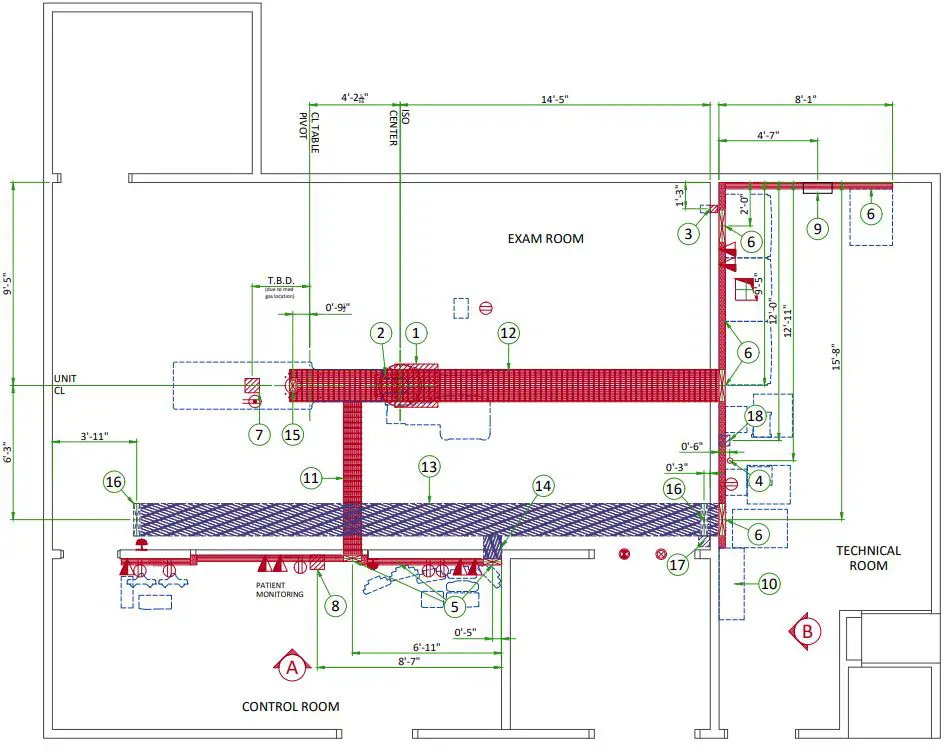
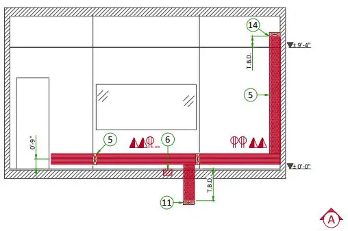
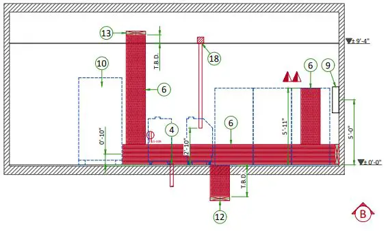
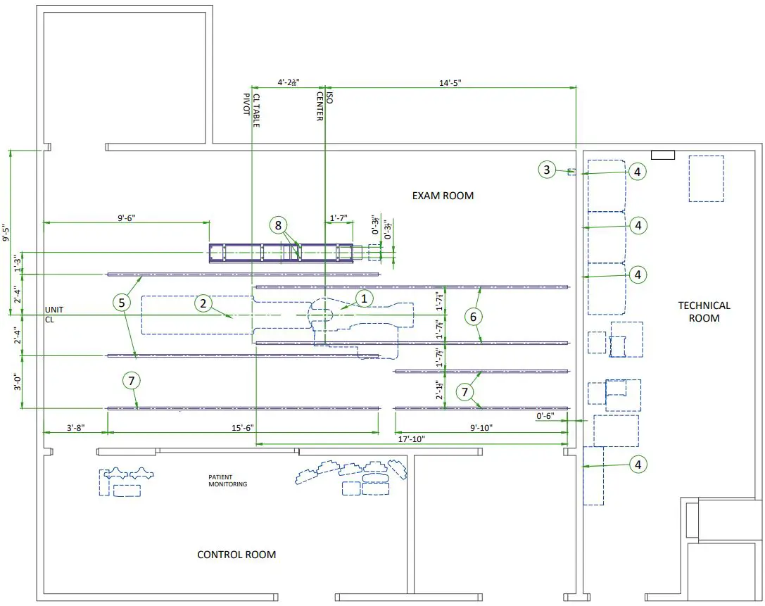
| ITEM | ELECTRICAL LAYOUT ITEM LIST |
| 1 | 24″ x 24″ x 12″ [600 x 600 x 300] Box below floor, (1) 6″ [150] dia. suitable length threaded |
| pipe, (2) 6″ [150] dia. locknuts and (4) 1″ [25] dia. locknuts. (LC gantry) | |
| 2 | (1) GE supplied fitting. (1) 12″ x 12″ x 6″ [300 x 300 x 150] Box, (1) 6″ [150] dia. bushing, (4) 1″ |
| [25] dia. bushing for water lines (LC Gantry) | |
| 3 | 4″x4″x4″ [100 x 100 x 100] flush wall junction box 12″ [300] below finished ceiling (x-ray |
| buzzer) | |
| 4 | Empty 3″ [75] conduit below floor for waterlines (LC chiller) |
| 5 | 10″ x 3 1/2″ [250 x 89] surface wall duct with minimum 2 dividers |
| 6 | 18″ x 3 1/2″ [450 x 89] surface wall duct with minimum 2 dividers |
| 7 | 8″ x 8″ x 6″ [200 x 200 x 150] box under table (PDM/TRAM) |
| 8 | 8″ x 8″ x 6″ [200 x 200 x 150] box below floor (patient monitoring equipment) |
| 9 | Local service disconnect (LOTO) |
| 10 | Power Distribution Box |
| 11 | 10″ x 3 1/2″ [250 x 89] below floor duct with minimum 2 dividers |
| 12 | 18″ x 3 1/2″ [450 x 89] below floor duct with minimum 2 dividers |
| 13 | 18″ x 3 1/2″ [450 x 89] above ceiling duct with minimum 2 dividers |
| 14 | 10″ x 3 1/2″ [250 x 89] above ceiling duct with minimum 2 dividers |
| 15 | 6″ x 4″ [150 x 100] riser duct from duct below to 1” [13] above finished floor with minimum 1 2 divider |
| 16 | 18″ x 3 1/2″ [250 x 89] vertical duct from duct above ceiling to finished ceiling with minimum 2 |
| dividers | |
| 17 | 6″x6″x6″ [150 x 150 x 150] flush ceiling box for waterlines (LP gantry) |
| 18 | 6″x6″x6″ [150 x 150 x 150] flush ceiling box for waterlines (LP chiller) |
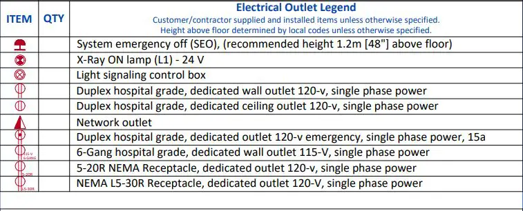
Electrical Outlet Legend
Additional Conduit Runs
| Additional Conduit Runs | |||||
| (Contractor Supplied and Installed) | |||||
| From (Bubble # / Item) | To (Bubble # / Item) | Qty | Usable length | Size (in) | |
| 18 LAT Water Line | 17 | LAT Gantry | 1 | 59 ft. | 3 |
| 4 AP Water Line | 2 | AP Gantry | 1 | 59 ft. | 3 |
| Light Signaling Control Box | Warning light | 1 | – | 1 2 | |
| Light Signaling Control Box | 6 | C2 Cabinet | 1 | – | 1 2 |
| Light Signaling Control Box | 120-V 1 phase power | 1 | – | As Req’d | |
| LED Transformer | Spooler | 1 | – | As Req’d | |
| LED Transformer | 120-V 1 phase power | 1 | – | As Req’d | |
| LED Lamp | Spooler | 1 | – | Cables | |
| come with | |||||
| spooler | |||||
| 3 X-Ray Buzzer | 6 | C1F Cabinet | 1 | 90 ft. | 11 2 |
| 3 X-Ray Buzzer | 5 | Control Room | 1 | 90 ft. | 11 2 |
| 6 Large Display Cabinet | 7 | TRAM/PDM | 2 | – | 3 |
| 10 Power Distribution Box | 6 | 20 kVA UPS | 2 | 68 ft. | As Req’d |
| 10 Power Distribution Box | Emergency off | 1 | – | 1 2 | |
| 10 Power Distribution Box | Emergency off | 1 | – | 1 2 | |
| 10 Power Distribution Box | 6 | C1F Cabinet | 2 | 68 ft. | 21 2 |
| 10 Power Distribution Box | 6 | C1F Cabinet | 2 | 68 ft. | 11 2 |
| 10 Power Distribution Box | 6 | C2 Cabinet | 1 | 68 ft. | 11 2 |
| 10 Power Distribution Box | 6 | C2 Cabinet | 1 | 68 ft. | As Req’d |
| 10 Power Distribution Box | 6 | C1L Cabinet | 2 | 68 ft. | 21 2 |
| 10 Power Distribution Box | 15 | Table (Table Power) | 1 | – | 2; As |
| Req’d | |||||
| 9 LOTO Disconnect | 480-V 3 phase power | 1 | – | As Req’d | |
| 9 LOTO Disconnect | 10 | Power Distribution Box | 1 | – | As Req’d |
| 5 Patient Monitoring Console | 16 | Monitor Bridge / Boom | 1 | – | 3 |
| 8 Patient Monitoring Console | 7 | TRAM/PDM | 2 | – | 3 |
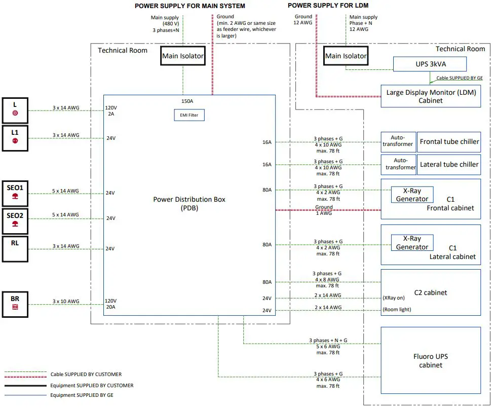
POWER REQUIREMENTS
| POWER SUPPLY | 3 PHASES+N+G 380/400/415/480 V ±10% |
| FREQUENCIES for 380/400/415 V | 50/60 Hz ± 3 Hz |
| FREQUENCY for 480 V | 60 Hz ± 3Hz |
| MAXIMUM INPUT POWER (0.1 sec max) | 150 kVA |
| NOMINAL LOAD (at 125 kV, 100 ms, 640 mA): | 60 kVA |
| MAXIMUM LINE RESISTANCE PER 2 PHASES WIRES (Ohm) | 380 V : 0.09 Ω / 400 V : 0.096 Ω / 415 V : 0.102 Ω / 480 V : 0.12 Ω |
- An EMI filter, provided by GE, is inside the PDB when Fluoro UPS CE is used.
- Neutral is mandatory for UPS control.
- TNS neutral point connection must be used.
- In case of IT or delta configuration without neutral, an isolation transformer is needed (supplied by customer)
- Three-phase, 5 conductors (3 phase conductors, 1 neutral and 1 protective earth conductor)
- Power supply should come into a power distribution box (PDB) containing the protective units and controls.
- The section of the supply cable should be calculated in accordance with its length and the maximum line resistance per 2 phases.
SUPPLY CHARACTERISTICS
- Power input must be separated from any others which may generate transients (elevators, air conditioning, radiology rooms equipped with high speed film changers …)
- All equipment installed with IGS system components must be powered separately (e.g. lighting, power outlets)
- Transients must be less than 2,000 V peak in common mode and 1,000 V in differential mode, with a duration limited to a few microseconds.
GROUND SYSTEM
- At least 35mm² copper from main ground point to the PDB.
- The equipotential link will be by means of an equipotential bar. This equipotential bar should be connected to the protective earth conductors in the ducts of the non IGS cableways and to additional equipotential connections linking up all the conducting units in the rooms where IGS units are located.
CABLES
- Power and cable installation must comply with the distribution diagram.
- All cables must be isolated and flexible, cable color codes must comply with standards for electrical installation.
- The cables from signalling and remote control (Y, SEO, L…) will go to PDB with a pigtail lenght of 1.5 m, and will be connected during installation.
- Each conductor will be identified and isolated (screw connector).
CABLEWAYS
The general rules for laying cableways should meet the conditions laid down in current standards and regulations, with regard to :
- Protecting cables against water (Cableways should be waterproof),
- Protecting cables against abnormal temperatures (Proximity to heating pipes or ducts),
- Protecting cables against temperature shocks,
- Replacing cables (Cableways should be large enough for cables to be replaced) ,
- Only GE cables are running inside cableways,
- Metal cableways should be grounded.
MANDATORY LOTO REQUIREMENTS
- Core system: A wall circuit breaker or equivalent device with LOTO capability must be installed on the mains line to the PBD. This device must be compatible with the power input specifications of the system. The customer is responsible for the procurement, delivery and installation of this breaker.
- LDM option: A wall circuit breaker or equivalent device with LOTO capability must be installed on the mains line to the LDM UPS. The rating of this device shall be 30A for UL and 16A for CE configurations. The customer is responsible for the procurement, delivery and installation of this breaker.
TYPICAL EQUIPOTENTIAL CONNECTIONS
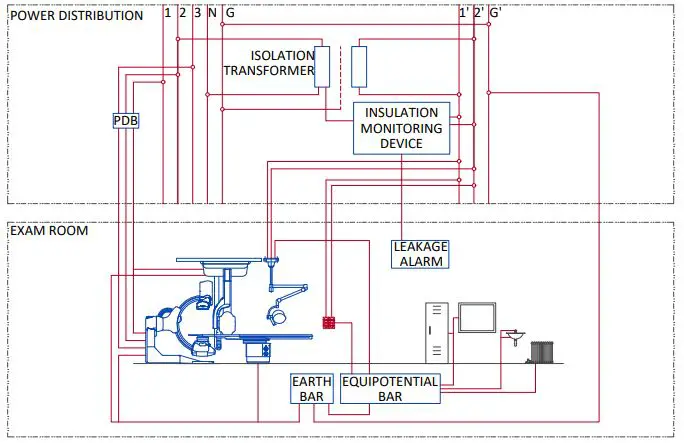
POWER DISTRIBUTION
- L X-Ray room warning light control panel
- L1 XRay ON light – 24V
- SEO1-2 Emergency OFF button with two normally closed (NC) contacts (1)
- RL Room light circuit: room lights off during X-Ray generation
- BR Injector wall outlet 10/16A+G
- (1) Location and/or quantity: refer to layout
NOTES: Max size of terminal block for PDB input cables: 4×3/0 AWG
FEEDER TABLE
| MIN. FEEDER WIRE SIZE, AWG OR MCM (sq. mm)/VAC | MINIMUM FEEDER WIRE LENGTH – ft (m) | |||||||
| 50 (15) | 100 (30) | 150 (46) | 200 (61) | 250 (76) | 300 (91) | 350 (107) | 400 (122) | |
| 480 VAC | *1/0 (55) | *1/0 (55) | *1/0 (55) | 1/0 (55) | 3/0 (85) | 4/0 (107) | 4/0 (107) | 300M (150) |
| GENERAL NOTES | ||||||||
| IN ALL CASES QUALIFIED PERSONNEL MUST VERIFY THAT THE FEEDER (AT THE POINT OF TAKE-OFF) AND THE RUN TO THE GE SYSTEM MEET ALL THE REQUIREMENTS STATED IN THE PIM | ||||||||
| FOR A SINGLE UNIT INSTALLATION, THE MINIMUM TRANSFORMER SIZE IS 225KVA, WITH 2.4% RATED REGULATION AT UNITY POWER FACTOR. RESULTANT MAXIMUM ALLOWABLE FEEDER REGULATION IS 3.6% | ||||||||
| THE GROUND WIRE TO EARTH SHALL BE A MINIMUM OF AWG #2 (UL) OR 35 MM² (CE) OR THE SAME SIZE (100%) AS FEEDER WIRES, WHICH EVER IS LARGER. | ||||||||
| WHEN A FLUORO UPS IS OR WILL BE INSTALLED, A NEUTRAL LINE IS MANDATORY. IF IT SCHEME AS EARTHING SYSTEM IS USED, AN ISOLATION TRANSFORMER IS REQUIRED WITH DELTA-WYE OR DELTA-STAR CONNECTION. | ||||||||
| * MINIMUM WIRE SIZE FOR CIRCUIT BREAKER, BASED ON RECOMMENDED OVERCURRENT PROTECTION. | ||||||||
INTERCONNECTIONS
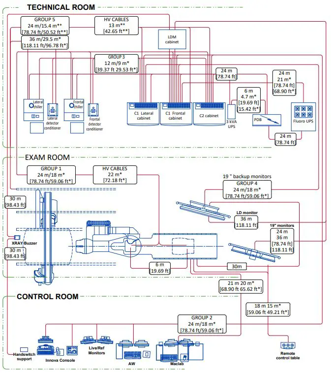
A mandatory component of this drawing set is the GE Healthcare Pre-Installation manual. Failure to reference the Pre Installation manual will result in incomplete documentation required for site design and preparation. Pre Installation documents for GE Healthcare products can be accessed on the web at: www.gehealthcare.com/siteplannin
GE does not take responsibility for any damages resulting from changes on drawings made by others. Errors may occur by not referring to the complete set of final issue drawing. GE cannot accept responsibility for any damage due to the partial use of GE final issue drawings, however caused. All dimensions are in millimeters unless otherwise specified. Do not scale from printed pdf files. GE accepts no responsibility or liability for defective work due to scaling from these drawings.


