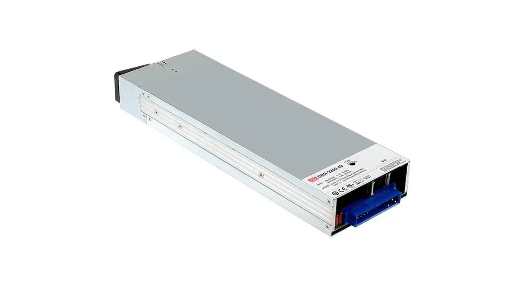
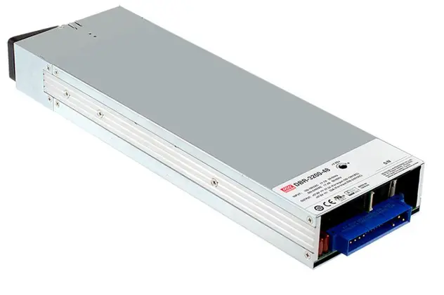
![]() 3200W Rack Mountable Front End Battery Charger
3200W Rack Mountable Front End Battery Charger
 DBR-3200 series
 https://www.meanwell.com/webapp/product/search.aspx?prod=DBR-3200&pdf=RFJQLTMyMDAsREJSLTMyMDAsREhQLTFVLUUucGRm&a=4
DBR-3200 Rack Mountable Front End Battery Charger
![]()
Applications
- Large scale DC UPS or emergency backup system
- Marine battery charger module
- Electric scooter or vehicle charger station
- Wastewater treatment system
- Electrolysis system
Features
- Charger for lead-acid batteries (Gel, flooded and AGM) and Li-ion batteries (lithium iron and lithium manganese)
- Built-in default 3 stage charging curves and programmable curve
- Built-in I°C interface, PMBus protocol (Optional CANBus protocol)
- Output voltage and current programmable
- Universal AC input / Full range
- Built-in active PFC function
- Forced air cooling by built-in thermal controlled DC fans
- Built-in OR-ing FET, support hot swap (hot plug)
- Active current sharing up to 12800W for one 19” rack shelf
- Protections: Battery under voltage / Battery no connection / Short circuit / Over voltage / Over temperature
- Optional conformal coating
- 5years warranty
Description
DBR-3200 is a 3200W single output AC/DC front-end charger in 1U low profile with high power density, 37W/inch’. It is an intelligent charger that has pre-loaded programmable charging curves for different types of lead-acid and li-ion batteries. Output programmable function allows user to adjust the charging voltage and current via the built-in potentiometer or PMBus protocol. Various protection mechanisms as well as the temperature compensation function are provided to assure normal and safe system operation.
The rack-mountable attribute fits DBR-3200 perfectly for the charging, backup or constant current source applications exploiting the rack architecture or central power management.
Model Encoding / Order Information
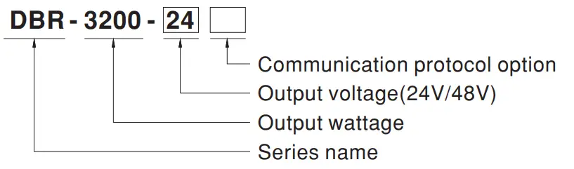
| Type | Communication Protocol | Note |
| Blank | PMBus protocol | In Stock |
| CAN | CANBus protocol | By request |
SPECIFICATION
| MODEL | DBR-3200-24 | DBR-3200-48 | |||
| OUTPUT | BOOST OUR& YCITAGE(VbcoeXelidl) | 28.8V | 57.6V | ||
| FLOATORRGE VOLIkfiE(VIegi(defaill) | 27.6V | 55.2V | |||
| CCEISTANTCURREIMCC)(default) | 110A | 55A | |||
| VOLTAGE ADJ. RANGE | By buit-in potentiometer, SVR | ||||
| 23.5 – 30V | 47.5 -58.8V | ||||
| RECOMMENDED BATTERY CAPACITY(AMP HOURS) Note.3 | 330 – 1000Ah | 180 – 550Ah | |||
| LEAKAGE CURRENT FROM BATTERY (Tye.) | <1.5mA | ||||
| INPUT | VOLTAGE RANGE NoteA | 90 – 264VAC 127 – 370VDC | |||
| FREQUENCY RANGE | 47 – 63Hz | ||||
| POWER FACTOR (Typ.) | 0.97/230VAC at ful load | ||||
| EFFICIENCY (Typ.) | 94.% | 195.% | |||
| AC CURRENT (Typ.) NoteA | 17A/230VAC | ||||
| INRUSH CURRENT (Typ.) | COLD START 55A/230VAC | ||||
| LEAKAGE CURRENT | <1.5mA/ 230VAC | ||||
| PROTECTION | OVER VOLTAGE | 31.5 – 37.5V | 163 -75V | ||
| Protection type : Shut down o/p voltage, re-power on to recover | |||||
| OVER TEMPERATURE | Shut down o/p voltage, recovers automatically after temperature goes down | ||||
| FUNCTION | OUTPUTVOLTAGEPROGRAIIIIABLEIPY) | Adjustment of output voltage is allowable to 75 – 125% of nominal output voltage. Please refer to the Function Manual. | |||
| OU1PUTCURRENT PROGRAMMABLE”, | Adjustment of output voltage is allowable to 20 – 100% of rated current. Please refer to the Function Manual. | ||||
| AUXILIARY POWER | 5V © 0.3A, tolerance ±10%, ripple 150mVp-p, 12V @ 0.8A, tolerance ±10%, ripple 450mVp-p | ||||
| REMOTE ON-OFF CONTROL | By electrical signal or thy contact Power ON:short Power OFF:open. Please refer to the Function Manual | ||||
| TEMPERATURE COMPENSATION | -3mV / ‘(.: / cell /(12V = 6 cells ; 24V = 12 cells ; 48V = 24 cells) | ||||
| DC OK SIGNAL | The isolated TTL signal out. Please refer to the Installation Manual | ||||
| AC OK SIGNAL | The isolated TTL signal out. Please refer to the Installation Manual | ||||
| ENVIRONMENT | WORKING TEMP. | -30 -+70°C (Refer to terating Curve’) | |||
| WORKING HUMIDITY | 20 – 90% RH non-condensing | ||||
| STORAGE TEMP., HUMIDITY | -40 – +85°C , 10 – 95% RH non-condensing | ||||
| TEMP. COEFFICIENT | ±0.03VC (0 – 50t ) | ||||
| VIBRATION | 10 – 500I-t, 2G 10min./1cyde, 60min. each along X, Y, Z axes | ||||
| SAFETY & EMC (Note 5) | SAFETY STANDARDS | UL62368-1, CSA C22.2 No. 62368-1, TUV BS EN/EN62368-1, EAC TP TC 004 approved | |||
| WITHSTAND VOLTAGE | UP-0/P:3KVAC I/P-FG:2KVAC 0/P-FG:1.5KVAC | ||||
| ISOLATION RESISTANCE | I/P-0/P, I/P-FG, 0/P-FG:100M Ohms / 500VDC / 25 t/ 70% RH | ||||
| EMC EMISSION | Parameter | Standard | Test Level! Note | ||
| Conducted | BS EN/EN55032 (CISPR32) | Class B | |||
| Radiated | BS EN/EN55032 (CISPR32) | Class A | |||
| Harmonic Current | BS EN/EN61000-3-2 | — | |||
| Voltage Flicker | BS EN/EN61000-3-3 | — | |||
| EMC IMMUNITY | BS EIWEN55024, BS EN/EN61000-6-2 | ||||
| Parameter | Standard | Test Level /Note | |||
| ESD | BS EN/EN61000-4-2 | Level 3, 8KV air ; Level 2, 4KV contact | |||
| Radiated | BS EN/EN61000-4-3 | Level 3 | |||
| EFT/ Burst | BS EN/EN61000-4-4 | Level 3 | |||
| Surge | BS EN/EN61000-6-2 | 2KV/Line-line 4KV/Line-Earth | |||
| Conducted | BS EN/EN61000-4-6 | Level 3 | |||
| Magnetic Field | BS EN/EN61000-4-8 | Level 4 | |||
| Voltage Dips and Interruptions | BS EN/EN61000-4-11 | >95% dip 0.5 periods, 30% dip 25 periods, >95% interruptions 250 periods | |||
| OTHERS | MTBF | 160.1K hrs min. Telcordia SR-332 (Belcore); 38.9K hrs min. MIL-HDBK-217F (25°C) | |||
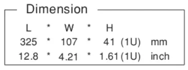
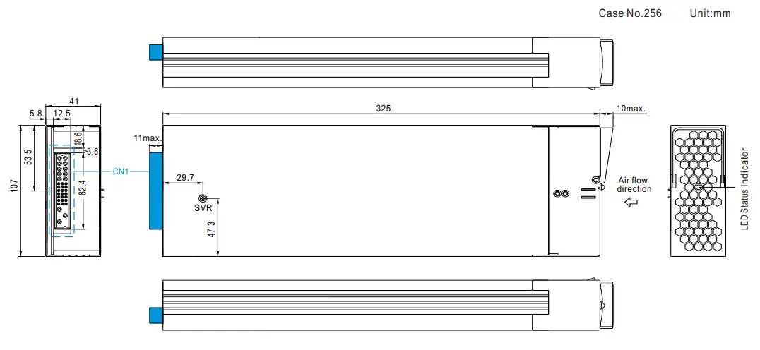
| DIMENSION | 325’107’41mm (L’WH) | ||||
| PACKING | 2.65144pcs/11.6Kg/0.93CUFT | ||||
| NOTE | 1. Modification for charger specificaion may be required for different battery specificaion. Please contact battery vendor and MEAN WELL for details. 2. All parameters NOT specially mentioned are measured at 230VAC input, rated load and 25°C of ambient temperature. 3. This is MEAN WELL’s suggested range. Please consult your battery manufacturer for their suggestions aboLt maximum charging current limitation. 4. Derating may be needed under low input voltages. Please check the derating curve for more detais. 5. The charger is considered a component which will be installed into a final equipment. Al the EMC tests are been exected by mourting the unit on a 00mm”900mm metal plate with 1mm of thickness. The final equipment must be re-confirmed that it il meets EMC directives. For guidance on how to perform these EMC tests, pi 6. The ambient temperature derating of 3.5’C/1000m with fanless models and of 5’C/1000m with fan models for operating attitude higher than 2000m(6500f). | ||||
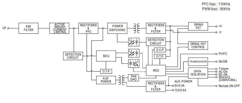
BLOCK DIAGRAM
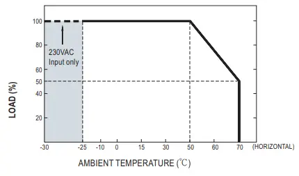
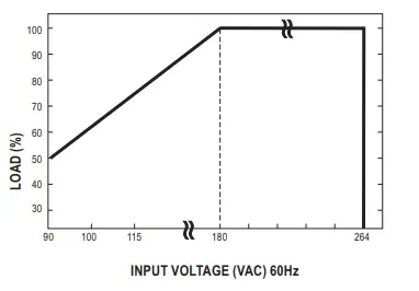
DERATING CURVE
STATIC CHARACTERISTICS
FUNCTION MANUAL
- PMBus Communication Interface
 DBR-3200 supports PMBus Rev. 1.1 with maximum 100KHz bus speed, allowing information reading, status monitoring, output trimming, etc. For detals, please refer to the Installation Manual.
 - Charging Curve By factory default, this charger performs the default curve which can be programmed via PMBus. To disable / enable the charging curve, change to a2 stage curve, a different curve frequently used for certain types of batteries in the industry, and soon, please refer to the Installation Manual. Toprogram the parameters of the charging curve, SBP-001, the smart battery charging programmer designed by MEAN WELL, and a personal
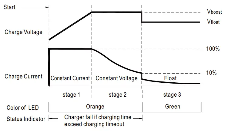
computer are needed. Please contact MEAN WELL for details. Default3 stage charging curve
3Stage Sutable for lead-acid batteries (flooded, Gel and AGM) and Li-ion batteries (ithiumiron and lthium manganese) Embedded 3 stage charging curves
MODEL Description Vboost \Moat CC(default) 24V Default, programmable 29. 28. 110A Pre-defined, gel battery 28 27. Pre-defined, flooded battery 28. 27. Pre-defined, AGM battery 29 27 48V Default, programmable 58. 55. 55A Pre-defined, gel battery 56 54. Pre-defined, flooded battery 57. 54. Pre-defined, AGM battery 58 54 Note :
When using this charger unit, please configured the system with recommended battery capacity defined by specification. Should battery capacily in use be much smaller sothat user needs to seta low current for charging, under such condition it might cause higher current ripple - Remote ON-OFF Control
The charger can be turned ON/OFF individually or along with other units in parallel by using the “Remote ON-OFF” function.
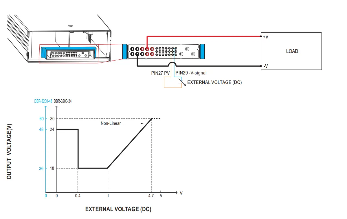
Between Remole ON-OFF and +5V-AUX Charger Status Switch Short oN Suitch Open OFF - Output Voltage Programming (or, PV / remote voltage programming / remote adjust / margin programming / dynamic voltage trim) In addtion to the adjustment via the built-in potentiometer, the output voltage can be trimmed to 75~125% of the nominal voltage by applying EXTERNAL VOLTAGE.

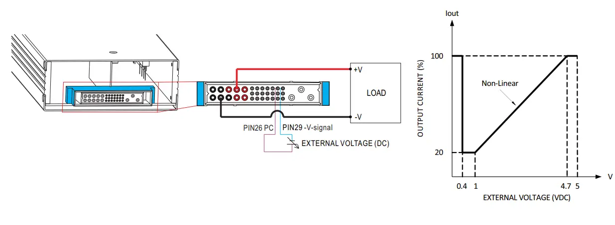
- Output Current Programming (or, PC / remote current programming / dynamic current trim) The output current can be trimmed to 20~100% ofthe rated current by applying EXTERNAL VOLTAGE.

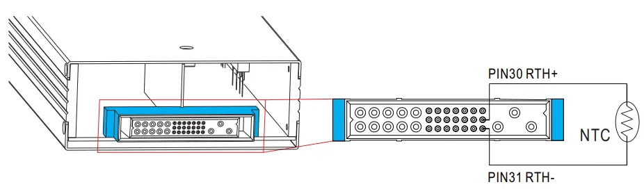
- Temperature Compensation
 To exploit the temperature compensation function, please attach the temperature sensor, NTC, to the battery or the battery’s vicinty. The charger s able to work normally withoutthe NTC.

MECHANICAL SPECIFICATION
![]() LED Status Indicators
LED Status Indicators
| LED | Description |
| Float (stage 3) | |
| Charging (stage 1 or stage 2) | |
| The LED will present a constant red light when the abnormal status (OTP, OLP, fan fail and charging timeout) arises. | |
| The LED will flash with the red light when the internal temperature reaches 60°C; under this condition, the unit still operates normally without entering OTP. (In the meantime, an alarm signal will be sent out through the PMBus interface.) |
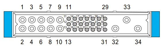
※ Input / Output Connector Pin No. Assignment(CN1) : Positronic PCIM34W13M400A1
| Mating Housing | Mating Housing |
| Pin No. | Function | Description |
| 1,2,3,4,6 | -V | Negative output terminal. |
| 5,7,8,9,10 | +V | Positive output terminal. |
| 11 | +12V-AUX | Auxiliary voltage output, 10.8-13.2V, referenced to GND-AUX (pin 12). The maximum load current is 0.8A. This output has the built-in “Oring diodes” and is not controlled by the Remote ON/OFF control. |
| 12 | GND-AUX | Auxiliary voltage output GND. The signal return is isolated from the output terminals (+V & -V). |
| 13 | +5V-AUX | Auxiliary voltage output, 4.5-5.5V, referenced to GND-AUX (pin 12). The maximum load current is 0.3A. This output has the built-in “Oring diodes’ and is not controlled by the Remote ON/OFF control. |
| 14 | SCL | For PMBus model: Serial Clock used in the PMBus interface. (Note.2) |
| CANL | For CANBus model: Data line used in CANBus interface. (Note.2) | |
| 15 | SDA | For PMBus model: Serial Data used in the PMBus interface. (Note.2) |
| CANH | For CANBus model: Data line used in CANBus interface. (Note.2) | |
| 16 | T-ALARM | High (4.5 – 5.5V) : When the internal temperature exceeds the limit of temperature alarm, or when fan fails. Low (-0.1 – 0.5V) : When the internal temperature is normal, and when fan works normally . The maximum sourcing current is 10mAand only for output(Note.2) |
| 17 | Remote ON-OFF | The unit can turn the output ON/OFF by electrical signal or dry contact between Remote ON/OFF and +5V-AUX. (Note.2) Short (4.5 – 5.5V) : Power ON ; Open (-0.1 – 0.5V) : Power OFF ; The maximum input voltage is 5.5V. |
| 18 | High (4.5 – 5.5V) : When the Vout 16V/32V ± 1V. Low (-0.1 – 0.5V) : When Vout a 16V/32V ± 1V. The maximum sourcing current is 10mA and only for output. (Note.2) DC OK is associated with battery low protection. | |
| DC-OK | ||
| 19 | AC-OK | High (4.5 – 5.5V) : When the input voltage is 87Vrms . Low (-0.1 – 0.5V) : When the input voltage is -75Vrms. The maximum sourcing current is 10mAand only for output. (Note.2) |
| 20 | DO | Interface lines for charging curve selection. (Note.1) |
| 21,22,23 | A2,A1,A0 | PMBus interface address lines. (Note.1) |
| 24,25 | DB,DA | Differential digital signal for parallel control. (Note.1) |
| 26 | PC | Connection for output current programming. (Note.1) |
| 27 | PV | Connection for output voltage programming. (Note.1) |
| 28 | +V(signal) | Positive output voltage signal. It cannot be connected directly to the load. |
| 29 | -V(signal) | Negative output voltage signal. It is for certain function reference; it cannot be connected directly to the load. |
| 30 | RTH+ | Temperature sense associated with the temperature compensation function. |
| 31 | RTH- | |
| 32 | FG | AC Ground connection. |
| 33 | AC/L | AC Line connection. |
| 34 | AC/N | AC Neutral connection. |
Note1: Non-isolated signal, referenced to [-V(signal)].
Note2: Isolated signal, referenced to GND-AUX.
![]()
![]()
![]()
![]() Downloaded from Arrow.com.
Downloaded from Arrow.com.


