Keston Combi 2 30kw and 35kw Output Combi Boiler Owner’s Manual
Features & specification
Offering first-class comfort in a compact, wall-hung appliance small enough to fit inside a standard kitchen cupboard*, the Keston Combi 2 range enables heating and hot water to be controlled independently, ensuring maximum comfort and efficiency.
Keston Combi 2 can be sited almost anywhere in the home, without the need for a separate tank. And because it connects to the unique Keston Twin Flue system, the boiler can be situated anywhere up to 27** metres from the flue outlet, helping to provide further flexibility when required.
Fully modulating, and with weather compensation, Keston Combi 2 provides excellent energy savings, making it the perfect choice for new or replacement installations alike.
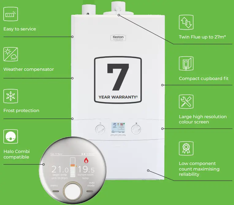
THE FACTS
- 7 year warranty†
- Easy to see pressure gauge
- Large backlit display with user friendly controls
- Low lift weight
- Low component count maximising reliability
- Compact dimensions
- Twin flue up to 27m
- 50mm muPVC (PVC-C) solvent weld flue allowing simple, cost effective installations
- Weather compensator supplied as standard making Keston Combi 2 Boiler Plus compliant out of the box
- Pre-fitted filling loop
- Inbuilt frost protection
- Fully modulating
- LPG conversion kit available
7 year warranty when installed with a Keston 22mm System Filter and registered within 30 days of installation. 5 year parts & labour warranty as standard. Terms and conditions apply.
- Please check
cupboard size prior to installation. - For the maximum total equivalent flue length, please refer to
the installation manual. - The only systems approved for this application are: Marley muPVC (PVC-C) Solvent Weld Waste System (50mm), Polypipe System 2000 muPVC (PVC-C) Solvent Weld Waste System (50mm), Polypipe Terrain Solvent Weld System (50mm) and Wavin Osma PVC-C Solvent Weld System (50mm). Please use the recommended Solvent Weld Cement for each system.
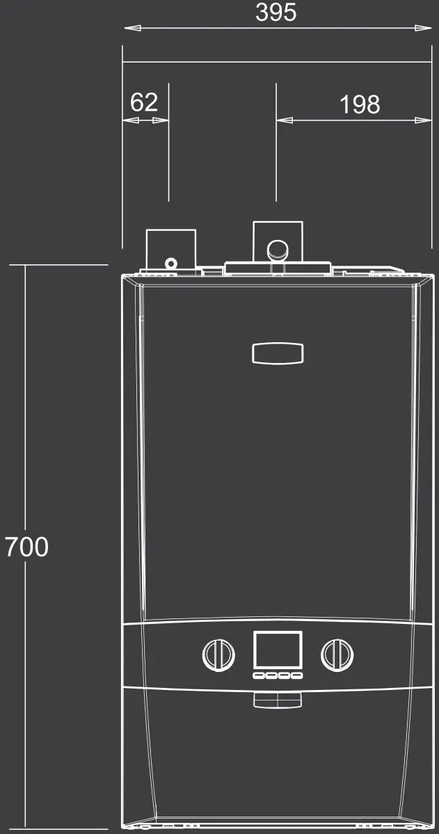
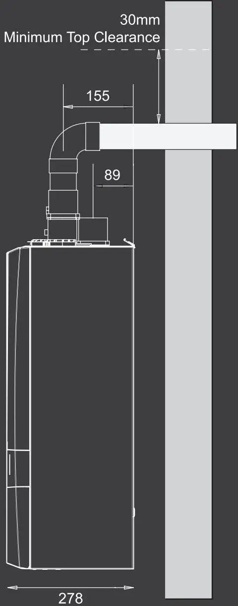
DIMENSION & CLEARANCES
Specification Data
| CENTRAL HEATING | C30 | C35 | |||
| CH Output @ 70°C | Max | kW | 24.2 | 24.2 | |
| Max | kW | 6.1 | 7.1 | ||
| CH Output @ 40°C | Max | kW | 25.6 | 25.6 | |
| Min | kW | 6.4 | 7.5 | ||
| CH Input | Nett CV Max | kW | 24.3 | 24.3 | |
| Nett CV Min | kW | 6.1 | 7.1 | ||
| CH Input | Gross CV Max | kW | 27.0 | 27.0 | |
| Gross CV Min | kW | 6.7 | 7.9 | ||
| CH Gas Consumption | Max | m3 /h | 2.512 | 2.512 | |
| Min | m3 /h | 0.627 | 0.734 | ||
| HOT WATER | C30 | C30 | |||
| DHW Output | Max | kW | 30.3 | 35.3 | |
| DHW Input | Nett CV M | kW | 30.4 | 35.4 | |
| DHW Input | Gross CV Max | kW | 33.7 | 39.3 | |
| DHW Gas Consumption | m3 /h | 3.135 | 3.657 | ||
| DHW Flow Rate at 35°C Rise | l/min | 12.4 | 14.5 | ||
| DHW Specific Rate | l/min | 14.5 | 16.9 | ||
| OTHERS | C30 | C35 | |||
| Seasonal Efficiency | SEDBUK 2005 | % | 91.1 | 91.1 | |
| SEDBUK 2009/2012 | % | 89.6 | 89.6 | ||
| Seasonal Space Heating Efficiency Class | A | A | |||
| NOx Classification | Class 6 | Class 6 | |||
| GENERAL DATA | C30 | C30 | |||
| Max Horizontal Flue Length | m | 27 Flue / 2 Air | 27 Flue / 2 Air | ||
| Max Horizontal Flue Length (Parallel) | m | 18 Flue / 18 Air | 15 Flue / 15 Air | ||
| Flue Terminal Diameter | mm | 50 | |||
| Gas Supply | 2H – G20 – 20mbar | ||||
| Gas Supply Connection | 15mm copper compression | ||||
| Injector Size | 15mm copper compression | ||||
| Injector Sizemm | 4.65 | 4.90 | |||
| Flow Connection (CH) | 22mm copper compression | ||||
| Inlet Connection (DHW) | 22mm copper compression | ||||
| Inlet Connection (DHW) | 15mm copper compression | ||||
| Outlet Connection (DHW) | 15mm copper compression | ||||
| Average Flue Temp – Mass Flow Rate (DHW) | 68°C – 13g/s | 73°C – 15g/s | |||
| CO2 Content (±0.7) (Min CH) | % | 8.5 | 8.8 | ||
| CO2 Content (±0.7) (Max DHW) | % | 9.3 | 9.7 | ||
| Max Working Pressure (Sealed Systems) | bar (psi) | 2.5 (36.3) | |||
| Max DHW Inlet Pressure | bar (psi) (kPa) | 10.0 (145) (1000) | |||
| Min DHW Inlet Pressure | bar (psi) (kPa) | 1.3 (18.9) (130) | |||
| Electrical Supply | 230V – 50Hz | ||||
| Power Consumption | W | 93 | 110 | ||
| Fuse Rating | External 3A / Internal: T4A HRC L250V | ||||
| Water Content (CH) | l (gal) | 1.2 (0.26) | |||
| Water Content (DHW) | l (gal) | 1.0 (0.22) | |||
| Weight (Packed) | kg | 32.9 | 32.9 | ||
| Maximum Installation Weight | kg | 28.6 | 28.6 | ||
Example Flue Installation
Keston Combi 2 C30 – Flue & Air Pipe Length
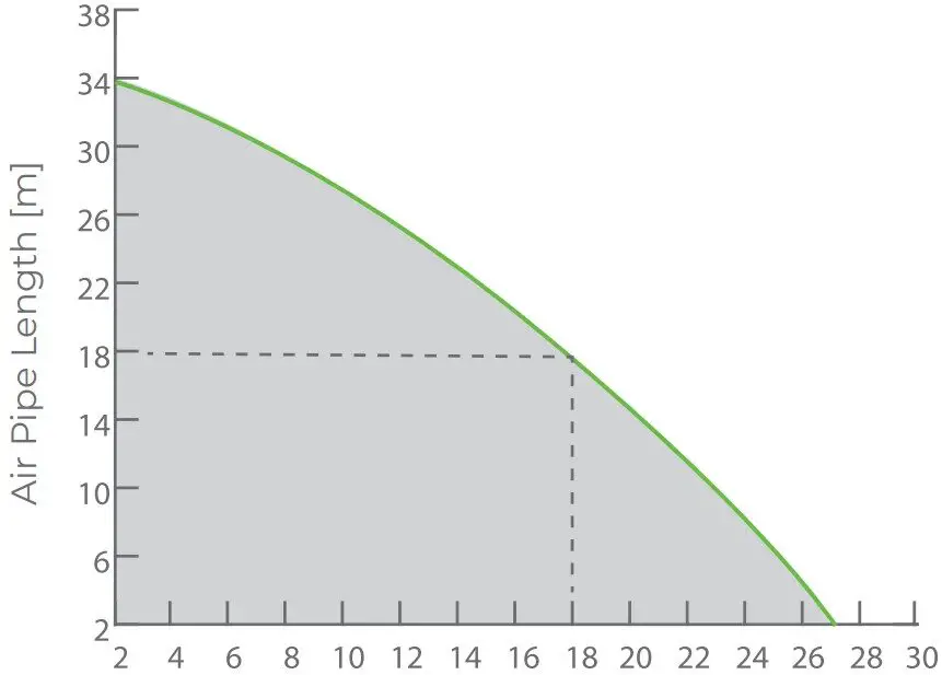
Flue Pipe Length [m]
![]() acceptable flue operating area
acceptable flue operating area
Graph indicates maximum flue run 27m with 2m air. Also, 18m flue with 18m air pipe for parallel twin flue run.
C53 HORIZONTAL
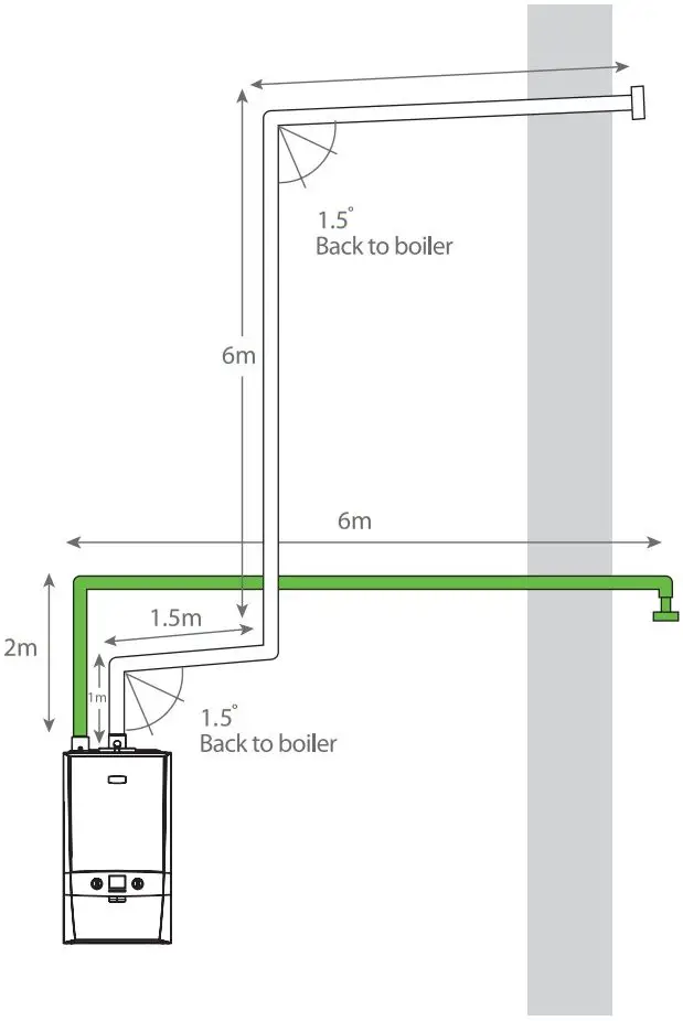
Calculations:
Flue
Elbows 3 x 1m = 3m
Straights 4+6+1.5+1 = 12.5m
Total = 15.5m
Air
Elbows 2 x 1m = 2m
Straights 6+2+0.1+1 = 8.1m
Total = 10.1m.
Keston Combi 2 C35 – Flue & Air Pipe Length
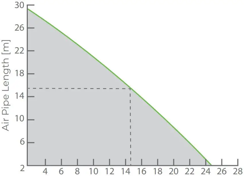
Flue Pipe Length [m
![]() acceptable flue operating area
acceptable flue operating area
Graph indicates maximum flue run 25m with 2m air. Also, 15m flue with 15m air pipe for parallel twin flue run.
C13 HORIZONTAL
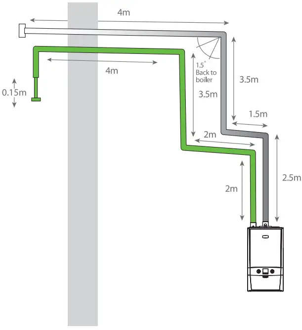
Calculations:
Flue
Elbows 3 x 1m = 3m
Straights 4+3.5+1.5+2.5 = 11.5m
Total = 14.5m
Air
Elbows 4 x 1m = 4m
Straights 2+2+3.5+4+0.15 = 11.65m 2 4 6 8 10 12 14 16 18 20 22 24 26 28 Total = 15.65m
The following minimum clearances must be maintainedfor operation and servicing.
Front of boiler – 450mm†
Sides of boiler – 2.5mm
Above boiler – 350mm, with 30mm above the flue
Below boiler – 100mm†
Dimensions:
| KESTON COMBI 2 | |
| Height | 700mm |
| Width | 395mm |
| Depth | 278mm |
- Or equivalent length.
- Can be reduced to 5mm for cupboard fit, 450mm required for servicing.
Tel: 01482 443 005 Fax: 01482 467 133
Keston Heating, PO Box 103, National Avenue, Kingston Upon Hull HU5 4JN
Keston.co.uk![]()


 Combi Boiler Instruction Manual")


