LUTRON Hi-lume Premier 0.1% EcoSystem-3-Wire Voltage LED Driver Instruction Manual

Installation
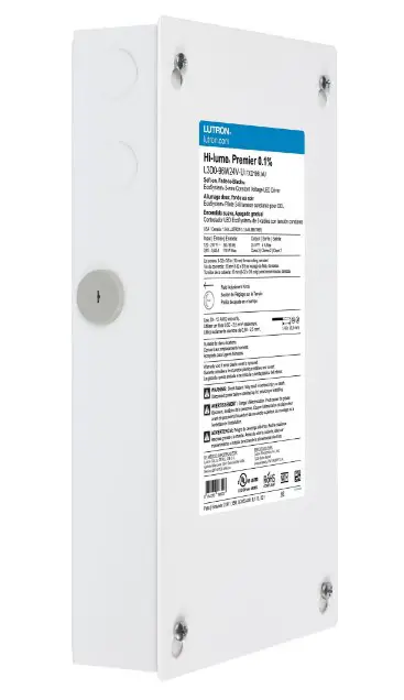
L3D0-96W24V-U UL® Listed Driver
Output: 2–96 W 24 V- Input: 120 V~/277 V~ 50 / 60 Hz, Max 110 W Important Notes: Please read before installing.
- For installation by a qualified electrician in accordance with all local and national electrical codes.
- Use copper conductors only.
- For indoor use only.
- For 277 V~ applications, a suitable barrier may be required between the non-Class 2 and Class 2 wiring, per local and national electrical wiring codes. For your convenience, the driver includes an optional barrier.
- Check to see that the driver type and rating are suitable for the application.
- DO NOT install if product has any visible damage.
- If moisture or condensation is evident, allow the product to dry completely before installation.
- Operate between 32 °F (0 °C) and 104 °F (40 °C) ambient.
- 0% to 90% humidity, non-condensing.
- Four 8-32 × 3/8 in (9.5 mm), serrated lid screws provided.
- For best practices, please refer to Application Note #591 (P/N 048591) at www.lutron.com

Need Help? Please visit the Hi-lume Premier 0.1% page at www.lutron.com or call Lutron Customer Assistance at 1.844.LUTRON1 Hi-lume Premier 0.1% EcoSystem / 3-Wire Voltage LED Driver (1.844.588.7661
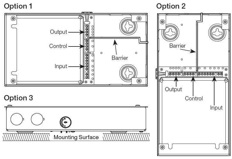
Mounting (mount as shown on the right)
- Remove top cover to access multi-sided mounting key holes.
- Mount driver per the options shown to the right.
Notes
• Minimum of 3 in (76 mm) required between any two LED drivers.
• Install in accordance with all national and local electrical codes.
• Mount driver in a position where it can be easily located and accessed if service or troubleshooting is necessary.
• Any other mounting configuration will require additional mechanical support. Improper installation may result in hazards to personnel or property. Wiring (wire as shown below)
 WARNING: Shock Hazard. May result in serious injury or death.
Turn off power at circuit breaker before installing the unit.
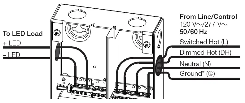
- Remove top cover to access the terminal blocks.
- Open necessary knockouts to pass wires into the wiring compartment.
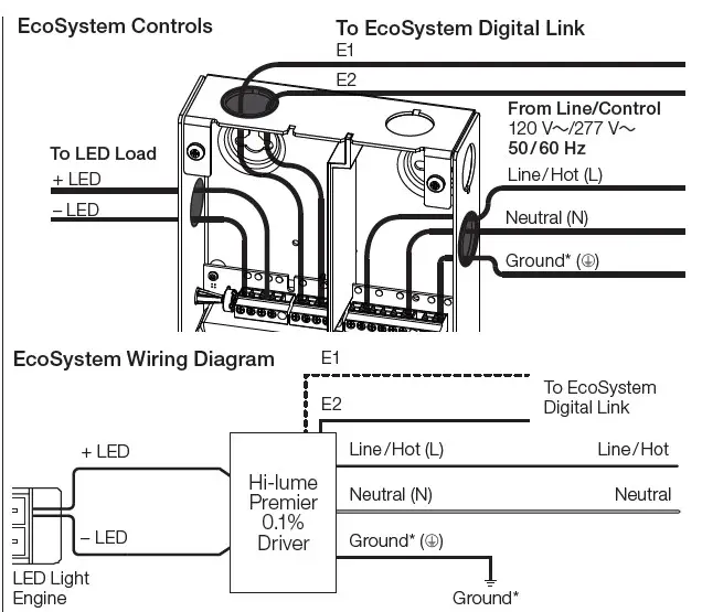
- Connect the necessary wires according to the illustration below. For E1 / E2 wiring, please refer to Application Note #142. Terminals accept 12 AWG to 20 AWG (0.50 mm2 to 2.5 mm2).
- Optional – An AC line cord may be used for a 120 V~ application. The line cord must include a grounded plug to be a valid installation as shown to the right.
Must be permanently connected fixed wiring for 277 V~ applications. - Optional – Add barrier between non-Class 2 and Class 2 wires (e.g., EcoSystem wiring shown below has E1 / E2 as Class 2, therefore barrier is placed between input and control terminal block).
- Rotate Field Adjustment Knob to full counter-clockwise position.
- Ensure compatible dimmer and load are installed and restore power to the circuit. See reverse side for Compatible Controls.
3-Wire Controls
3-Wire Wiring Diagram
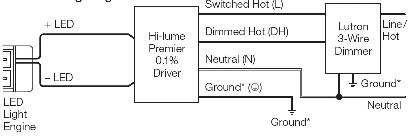
A barrier (included) in the wiring compartment separates non-Class 2 and Class 2 wires. Barrier can be placed between control and output
terminals (Option 1) or between input and control terminals (Option 2).
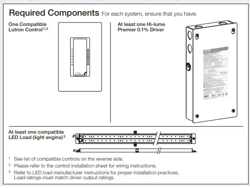
Hi-lume Premier 0.1% EcoSystem / 3-wire Voltage LED Driver Compatible Controls
Compatible Controls
- 3-Wire Controls
- EcoSystem Controls
Consult individual component installation guides for more details.
Driver Leads
Maximum wire length between LED driver and start of the light engine:
| Wire Gauge* | Maximum Lead Length |
| 24 AWG (0.20 mm2)* | 6 ft (1.8 m) |
| 22 AWG (0.75 mm2)* | 10 ft (3.0 m) |
| 20 AWG (0.50 mm2) | 15 ft (4.5 m) |
| 18 AWG (0.75 mm2) | 25 ft (7.62 m) |
| 16 AWG (1.0 mm2) | 40 ft (12.2 m) |
| 14 AWG (1.5 mm2) | 60 ft (18.3 m) |
| 12 AWG (2.5 mm2) | 100 ft (30.5 m) |
| 10 AWG (4.0 mm2)* | 150 ft (45.7 m) |
* To use wire gauges larger or smaller than terminal blocks’ rated gauge of
20 AWG to 12 AWG (0.50 mm2 to 2.50 mm2), connect 12 in (30 cm) or less of rated wire from terminal and connect with larger or smaller wire.
Field Adjustment Knob
Adjusting knob on the outside of the enclosure changes the minimum light level that is reached during normal operation. This feature enables the user to address light output mismatch between two or more drivers at low-end dim level. Driver is initially defaulted to the minimum light output when at low-end. For more information, please refer to Application Note #591 (P/N 048591) at www.lutron.com
- Ensure knobs on all drivers are in the full counterclockwise position.
- Set control to get lowest light level.
- Turn knob clockwise to adjust light output to match the brightest driver.
- Repeat steps 2-3 for the remaining drivers.
Compatible Controls
For assistance in selecting controls, contact our LED Center of Excellence.
For a complete list of compatible controls, see www.lutron.com/hilumepremiervoltagecontrols
This device complies with part 15 of the FCC Rules. Operation is subject to the following two conditions:
- This device may not cause harmful interference
- This device must accept any interference received, including interference that may cause undesired operation.
277 V~ NOTE: This equipment has been tested at 277 V~ and found to comply with the limits for a Class A digital device, pursuant to part 15 of the FCC Rules. These limits are designed to provide reasonable protection against harmful interference when the equipment is operated in a commercial environment. This equipment generates, uses, and can radiate radio frequency energy and, if not installed and used in accordance with the instruction manual, may cause harmful interference to radio communications. Operation of this equipment in a residential area is likely to cause harmful interference in which case the user will be required to correct the interference at their own expense.
120 V~ NOTE: This equipment has been tested at 120 V~ and found to comply with the limits for a Class B digital device, pursuant to part 15 of the FCC Rules. These limits are designed to provide reasonable protection against harmful interference in a residential installation. This equipment generates, uses and can radiate radio frequency energy and, if not installed and used in accordance with the instructions, may cause harmful interference to radio communications. However, there is no guarantee that interference will not occur in a particular installation. If this equipment does cause harmful interference to radio or television reception, which can be determined by turning the equipment off and on, the user is encouraged to try to correct the interference by one or more of the following measures:
- Reorient or relocate the receiving
- Increase the separation between the equipment and
- Connect the equipment into an outlet on a circuit different from that to which the receiver is connected.
Consult the dealer or an experienced radio/TV technician for help.
L3D0-96W24V-U Troubleshooting
| Problem | Possible Solution |
| LED does not illuminate at high-end | • Verify that the system is wired correctly according to wiring diagram and powered. • Verify that the LED load is wired correctly; +LED to positive, -LED to negative. • Verify that the LED load is for “constant-voltage” applications with PWM dimming. • Verify that the LED load is compatible with the specified voltage output of the driver. • Lutron drivers are not for use with MR16 LED lamps. |
| LED does not illuminate at low-end | • Verify that the low-end trim on the control is set properly. • Turn Field Adjustment Knob clockwise until desired low-end operation is obtained. |
| LED does not dim | • Verify that Switched Hot and Dimmed Hot are connected to the proper terminals for 3-wire control. • Verify EcoSystem control wiring (E1 and E2) is wired according to the instructions for digital control. |
| LED turns on / off abruptly without Soft-on, Fade-to- Black feature | • Turn Field Adjustment Knob counter-clockwise until desired low-end operation is obtained. • 3-wire control does not have Soft-on, Fade-to-Black dimming technology. |
| LED is flashing, flickering, dropping out, or has poor dimming performance | • Verify that a compatible dimmer is being used to control the driver. • Verify that the input voltage is within the rated limits. • Verify that Switched Hot and Dimmed Hot are connected to the proper terminals. • Verify that the LED load is for “constant-voltage” with PWM dimming applications. • Verify that the length of wires between driver and LED does not exceed specification. • Verify that the rated voltage is present at the driver. • Certain types of LED loads may be incompatible.* Verify that the LED load is within the specified wattage range of 2 W to 96 W. • Lutron drivers are not for use with MR16 LED lamps. |
| LED is flashing slowly (6 to 8 second interval) | • Verify that the LED load does not exceed the maximum specified power rating of the driver (96 W). • Verify that the LED load matches the specified voltage output of the driver. • Verify that the length of wire between driver and LED does not exceed specification. • Certain types of LED loads may be incompatible. * |
| LED output appears dim at high-end | • Verify that rated line voltage is present at the terminal. • Verify that the driver is operating in an environment within its ambient temperature rating. • Verify that the driver is not located adjacent to other heat producing devices. Verify that space between drivers is greater than 3 in (76 mm). • Verify that the maximum lead length is not exceeded per Lutron recommendation. • Verify that the LED load is installed per manufacturer’s instructions. • Verify that the LED load is compatible with the specified voltage output of the driver. |
| Not all LED strips/fixtures illuminate | • Verify that multiple LEDs connected to a single driver are properly wired. • Verify that the LED load is installed per manufacturer’s instructions. |
| Not all LEDs on the same strip are evenly lit | • Verify that the length of wire between the driver and LED does not exceed specifications. • Verify that the LED load is for “constant-voltage” with PWM dimming applications. • Verify that the LED load is installed per manufacturer’s instructions. |
| LED is brighter / hotter than expected | • Verify that the LED load is compatible with the specified voltage output of the driver. |
Certain constant-voltage loads may have added Contact the Lutron LED Center of Excellence at 1.877.346.5338 or [email protected] for more information about these loads.


