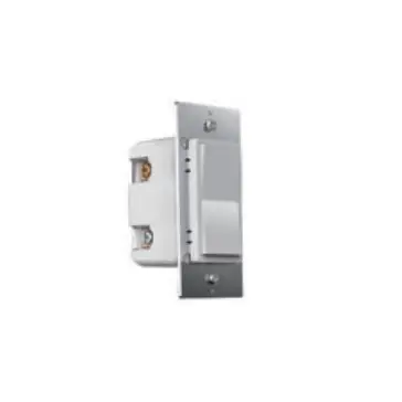
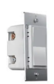
Pure Edge Lighting Wifi Smart Wireless In Wall Dimmer Switch
Included in Box
- Switch x1

- wiring x1

- screws x2


Specifications
Power: 120V AC, 60Hz
Wireless Frequency: 2.4GHz
Wireless Standard: IEEE802.llb/ g/n
Maximum Load: 150W LED S00W Incandescent
Temperature Range: 32° F~104° F
Range: up to 50 ft radius from Wi-Fi Access point
For indoor use.
Installation
Few Quick Reminders
A quick note before we go over the wiring schematics. Please do not try installing this device if you are unsure of how electrical ci rcuits operate within your home. As exciting as it is to have a smart switch installed, it can be dangerous and even life-threatening if you do not install this correctly. Please consult a qualified electrician if necessary. With that said, here are a few other warnings we’d like to point out for your safety:
HOW TO INSTALL THE WIRES

![]() Line (hot) – black (connected to power)
Line (hot) – black (connected to power)
![]() Neutral-white
Neutral-white
![]() Load – black (connected to lighting/3-way)
Load – black (connected to lighting/3-way)
![]() Traveler – red/other(connected to lighting /3-way)
Traveler – red/other(connected to lighting /3-way)
- Unscrew: carefully turn the screw counterclockwise to leave enough space for the wire to be inserted between gold and silver contacts. Do not unscrew the screws completely.

- Press down on screw

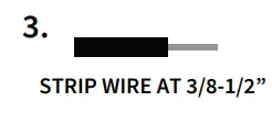
- Insert the wire: make sure the wire is completely straight, then insert it into the terminal between gold and silver contact. Do not wrap the wire around the screw!

- Tighten: Turn the screw clockwise to t ighten the wire between gold and silver contacts. Pull on wires to make sure the wires are locked!

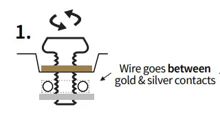

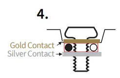
Note: There aire 2 holes for each terminal that can be used in the connection.
Note before installation
- The In-Wall Smart On/Off Switch must not exceed 150W LED/S00W Incandescent.
- Works with traditional 3-way on/off for 2 location control. It can only be connected with traditional non-smart 3 way/4 way on-off combinations, don’t use a smart switch or a smart dimmer!
- The colors of the wires may not match those in our diagrams so please make sure you’ve identified all wires correctly based on their source, not only by color.
- Please check the origina l 3-way wiring in your home before installation, and then follow the wiring diagram in the manual.
- Install the smart switch in t he electrical box which directly connects to the power Line and Neutral.
- This switch requires a Neutral for installation
- Not recommended for use with a fan.
If you have any questions, please contact us at [email protected]
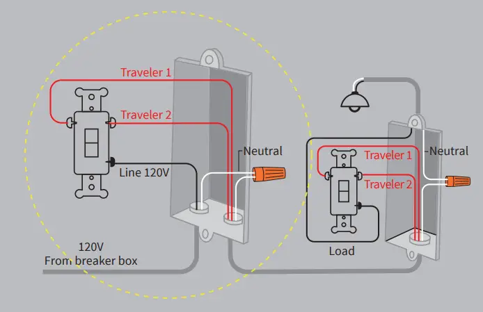
Wiring Diagram
Installation
- Tools Needed: Flat Head Screwdriver.
- Turn power OFF at circuit breaker or fuse box.

- Remove wallplate.
- Remove the switch mounting screws.
- Disconnect the wires and label them after removing the old switch.(Please use our sticker)

- Carefully remove the switch from the electrical box. (DO
NOT disconnect the wires.) - There are up to five screw terminals on the smart switch, each of these are marked (Please refer to: HOW TO INSTALL THE WIRES)
- After successful wiring, install the wall plate with the included screws.
- The Ground was excluded from the diagram to simplify the illustration. Please make sure the ground wires are connected to the switches respectively.
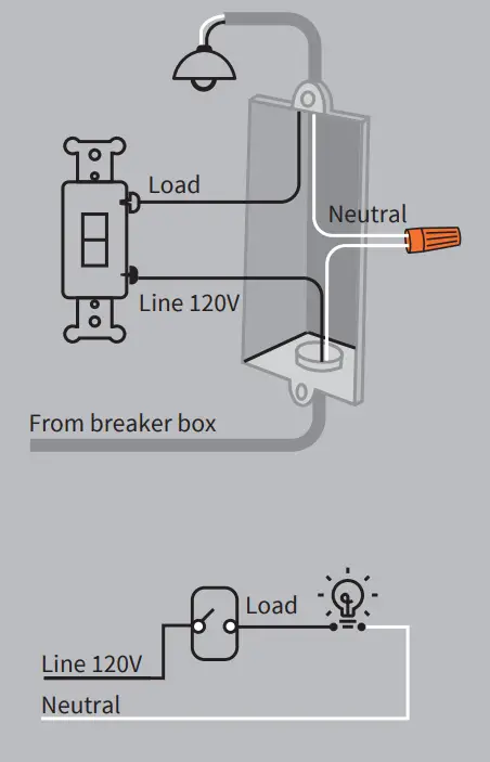
Single-pole Wiring
traditional/non-smart
smart
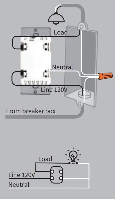
NOTE:
- Neutral required. If the electrical box does not have a Neutral, please stop! Connect the white wire to neutral terminal (use the white jumper that is included in the packaging.)
- Before the old switch is detached, please identify the common terminal.
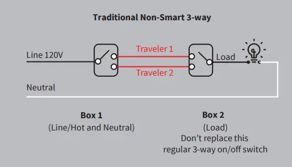
- Only works with a traditional non-smart 3-way on/off for 2 location control. It can only be connected with a traditional non-smart 3-way on/off switch, Not for use with a smart switch or smart dimmer.
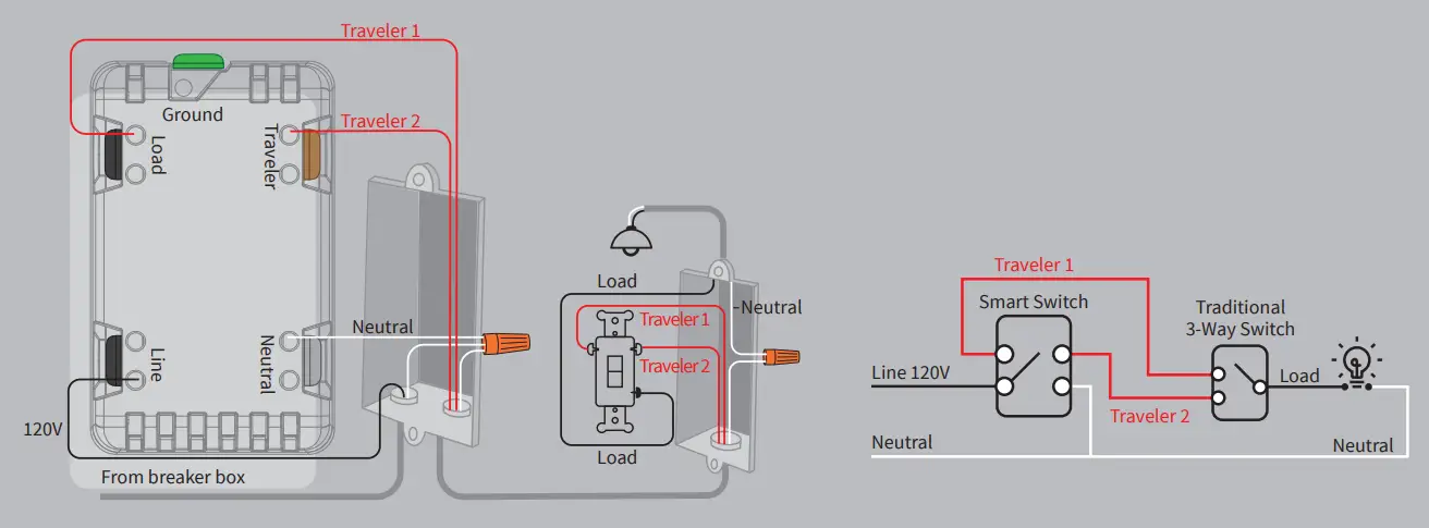
pole Wiring
traditional/non-smart 3-way
smart3-way
App Pairing
- Please scan the QR code to download the application “WiZ Connected”.
- You may a lso find the WiZ app in the Apple App Store or the Google Play Store under “WiZ Connected”
- After you download the WiZ Connected App and register a new account, please follow the instructions below to set up your smart switch.
For WiZ Pro Dashboard Users: WiZ Pro Dashboard account and home must be created before starting commissioning in the WiZ app. Please create an account on WiZ Pro Dashboard. Then create your home or location. After doing so, you may proceed to create an invitation in the dashboard by going to “settings” and then the “members” tab. By clicking on the “Invite” button you will be able to generate an invitation to access this dashboard location in the WiZ app. From there you can proceed with commissioning in the WiZ app but also have the added functionality of the Dashboard desktop application.
Connected by

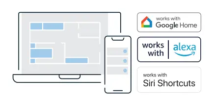 |  |
|
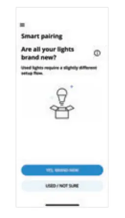
Smart Pairine
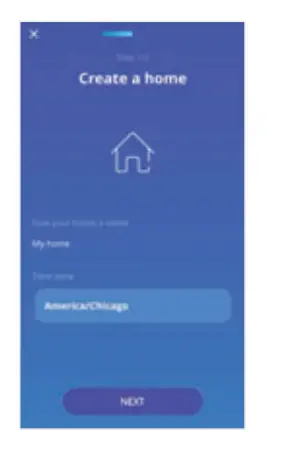
- After downloading the “WiZ Connected” app, follow the steps on screen to create or join a home.

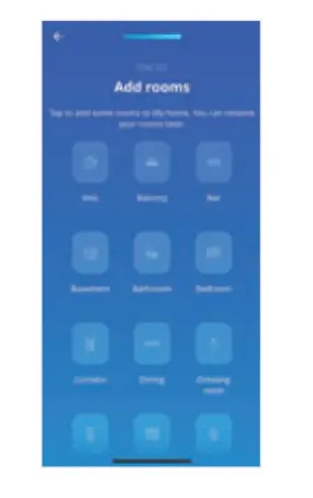
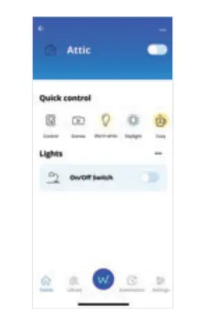
- Add rooms to your Home
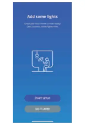
- Press “Start Setup” to add your new connected switch.
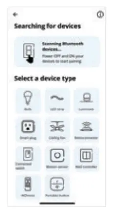
- Select connected switch

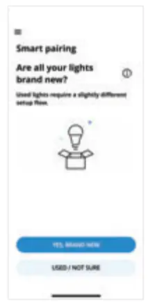
- If your device is brand new please select”Yes, Brand New” to continue the smart pairing process

- Enter the Wi-Fi network name and password. Your phone should be connected to the same 2.4 GHz network for pairing purposes.
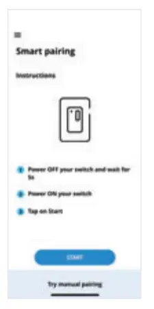
- Follow the on screen instructions for smart pairing

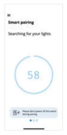
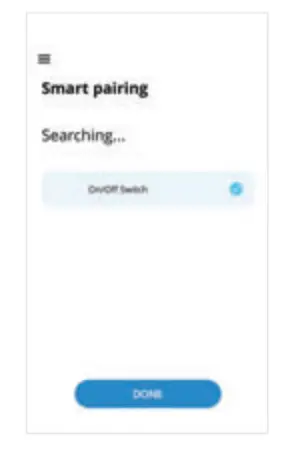
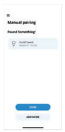
- Wait while the app locates and pairs with your switch
- After pairing is complete press Done.

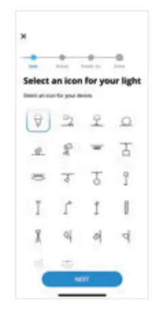
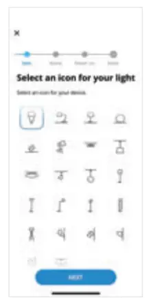
- Follow the s”teps to rename your device, select icon, and finish the setup.

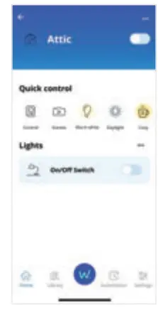
- Your smart switch is now ready to use


This equipment complies with FCC radiation exposure limits set forth for an uncontrolled environment. This equipment should be installed and operated with minimum distance 20cm between the radiator your body.
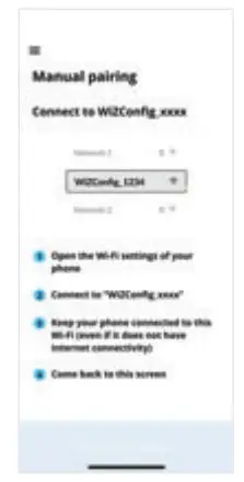
Manual Pairing
- If you are not sure if your device has been previously used please select “Used/ Not Sure.”

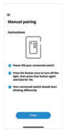
- Follow the inst-ructions on the WiZ App for Manual Pairing
- Enter your mobile device network settings and connect to “WIZ Config_ XXXX” network
- Return back to the WiZ App and wait until the dimmer is ready and connected

- Follow the steps on screen to rename your device, select icon, and finish the set up
- Your smart switch is now ready to use
FCC
This device complies with part 15 of the FCC and Industry Canada license-exempt RSS standard(s). Operation is subjected to the following two conditions: (1) this device may not cause harmful interference, and (2) this device must accept any interference received, including interference that may cause undesired operation.
FCC NOTE: The manufacturer is not responsible for any radio or TV interference caused by unauthorized modifications to th is equipment. Such modifications could void the user’s authority to operate the equipment.
– Reorient or relocate the receiving antenna.
– Increase the separation between t he equipment and receiver.
– Connect the equipment into an outlet on a circuit different from that to which the receiver is connected.
– Consult the dealer or an experienced radio/TV technician for help
NOTE: This equipment has been tested and found to comply with the limits for a Class B digital device, pursuant to Part 15 of the FCC Rules. These limits are designed to provide reasonable protection against harmful interference in a residential installation. This equipment generates, uses and can radiate radio frequency energy and, if not installed and u sed in accordance with the instructions may cause harmful interference to radio communications. However, there is no guarantee that interference will not occur in a particular installation. If this equipment does cause harmful interference to radio or television reception, which can be determined by t urning the equipment off and on, the user is encouraged to try to correct the interference by one or more of the following measures:
Important note: To comply with the FCC RF exposure compliance requ irements, no change to the antenna or the device is permitted. Any change to the antenna or the device could resu lt in the device exceeding the RF exposure requirements and void user’s authority to operate the device.
![]() CAUTION- PLEASE READ!
CAUTION- PLEASE READ!
This device is intended for installation in accordance with the National Electric Code and local regulations in the United States, or the Canadian Electrical Code and loca l regulations in Canada. If you are unsure or uncomfortable about performing this installation consult a qualified electrician.
![]() WARNING – SHOCK HAZARD
WARNING – SHOCK HAZARD
TURN OFF THE POWER to the circuit for the switch and lighting fixture at the service panel (circuit breaker) prior to insta llation. ALL WIRING CONNECTIONS MUST BE MADE WITH THE POWER OFF to avoid personal injury and/or damage to the switch.
![]() OTHER WARNINGS
OTHER WARNINGS
Risk of Fire
Risk of Electri c al Shock
Risk of Burns
Vl.O
WiZ Pro Software Suite
- Grant access permission to different stakeholders
- A clear overview to monitor lights with their mapped location
- Full range of configurations and remote control
- Comprehensive reporting on device status
- An interface dedicated to Installers
- Extends capabilities of installation of WiZ Pro products
- For end users to have simple, quick control on a daily basis
- Rich features including Scenes and Rhythms
 |  |