![]()
INSTALLATION INSTRUCTIONS
Q-TEC Wall Sleeve
Models:
| QWS42A QWS42A-16 | QWS42A-19 QWS42A-20 | QWS42A-23 QWS42A-30 |
GETTING OTHER INFORMATION AND PUBLICATIONS
The following publications can help when installing the wall sleeve. They can usually be found at the local library or purchased directly from the publisher. Be sure to consult the current edition of each standard.
The standard for the Installation of Air
Conditioning and Ventilating Systems …………………………………….ANSI/NFPA 90A
Standard for Warm Air Heating and Air Conditioning Systems …………ANSI/NFPA 90B
In addition, if may be helpful to consult the latest revision of the Q-TEC Installation Instructions manual 2100-742.
For more information, contact these publishers:
| ACCA Air Conditioning Contractors of America 1712 New Hampshire Ave. N.W. Washington, DC 20009 Telephone: (202) 483-9370 Fax: (202) 234-4721 | ANSI American National Standards Institute 11 West Street, 13th Floor New York, NY 10036 Telephone: (212) 642-4900 Fax: (212) 302-1286 | ASHRAE American Society of Heating, Refrigeration and Air Conditioning Engineers, Inc. 1791 Tullie Circle, N.E. Atlanta, GA 30329-2305 Telephone: (404) 636-8400 Fax: (404) 321-5478 |
INSTALLATION
Shipping Damage
Upon receipt of equipment, the carton should be checked for external signs of shipping damage. If damage is found, the receiving party must contact the last carrier immediately, preferably in writing, requesting inspection by the carrier’s agent.
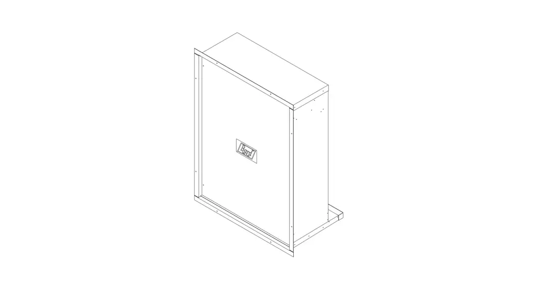
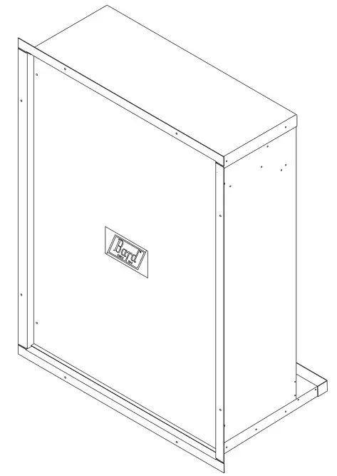
General
The QWS42A Series wall sleeve is designed for use with Q-TEC heat pumps. The QWS42A is for use on installations with a wall thickness of 5″ to 14″. The
QWS42A-16 is for use with wall thickness of 16″. The
QWS42A-19 is for use with wall thickness of 19″. The
QWS42A-20 is for use with wall thickness of 20″. The
QWS42A-23 is for use with wall thickness of 23″. The
QWS42A-30 is for use with wall thickness of 30″. One
QWS42A Series wall sleeve is required for each heat pump to be installed.
The equipment covered in this manual is to be installed by trained service and installation technicians. These instructions explain the recommended method to install the wall sleeve. These instructions and any instructions packaged with any separate quipment required to make the entire air conditioning system should be carefully read before beginning the installation.
While these instructions are intended as a general recommended guide, they do not supersede any national and/or local codes in any way. Authorities having jurisdiction should be consulted before the installation is made.
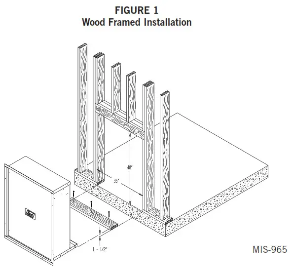
Installation – Wood Framed Walls
For wood frame construction walls, the dimensions of the opening must be 48″ tall by 35″ wide. A 2 x 6 header will be required for the opening. The sides of the opening must have trimmer studs to support the header and to provide a structural member on which to fasten the sleeve (see Figure 1). All of the dimensions are referenced from the finished floor height.
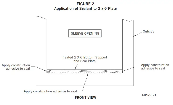
After the opening is framed, a treated 2 x 6 bottom support and seal plate must be cut to fit in the bottom of the opening. Construction adhesive should be applied to the 2 x 6 before it is put in place. This will help hold the plate in place and provide an additional seal for the bottom of the opening. The treated 2 x 6 must be fastened to the bottom of the opening flush to the finished surface of the outside wall. The 2 x 6 must be sealed to the outside wall with construction adhesive. Any gaps between the sides of the 2 x 6 plate and the opening must also be sealed (see Figure 2).
NOTE: Actual thickness of 2 x 6 must be 1-1/2″.
Once the opening is framed, the sheeting can be installed; the sheeting material must not extend into the opening. The sleeve should be test fit into the opening to make sure of the dimensions.
The sleeve must be inserted into the opening from the outside of the building. The bottom of the sleeve must be level from side to side and the sleeve must be square in the opening. A slope is built into the bottom of the sleeve from the inside to the outside. This will allow any water that gets into the sleeve to drain out. Once the test fit is completed, the sleeve must be removed from the opening and two 1/4″ beads of the sealant must be applied to the mounting flanges of the sleeve (see Figure 3 on page 5). The sleeve is then re-inserted into the prepared opening from the outside of the building. All of the mounting flanges must contact the exterior wall. Check to see that there is enough sealant to make this joint watertight. Additional sealant must be applied as necessary
The sleeve must be centered in the opening, and the bottom of the sleeve must be checked to make certain that it is level from side to side. The bottom flange should be secured to the wall by using two screws through the holes in the bottom mounting flange of the sleeve. The sleeve must be checked to make sure that it is square in the opening. Once the sleeve is square, the side and top mounting flanges of the sleeve must be secured to the wall with screws through the holes in the flanges. The gaps between the side, top, and bottom flanges must be filled with additional sealant.
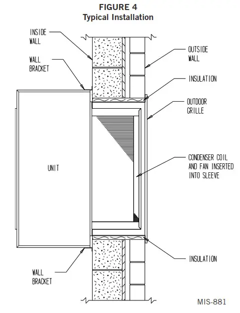
On the inside of the building, the gaps between the sleeve and the opening must be filled with insulation. This will help insulate the sleeve and prevent infiltration of any unwanted outdoor air (see Figure 4).
If the Q-TEC unit will be drained through the wall, the drain line must be installed through the wall. See the latest version of Q-TEC Installation Instructions manual 2100-742 for information on drain installation.
Installation – Masonry Construction Walls
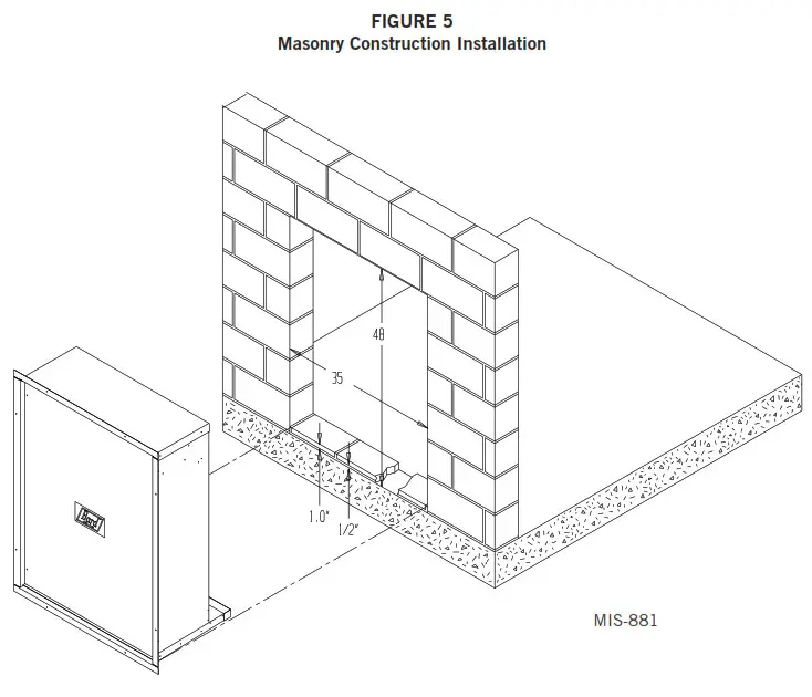
For masonry construction walls, the dimensions for the opening will be 48″ tall by 35″ wide. These dimensions are measured from the finished floor height (see Figure 5). These will be the finish dimensions of the opening.
A 1-1/2″ spacer needs to be installed in the bottom of the opening to raise the sleeve off the floor. Masonry blocks 1″ thick, minimum of 6″ wide, with 1/2″ mortar between the block and floor will provide the required spacing. These blocks are to be laid flush with the outside wall and must provide a water-tight seal to the floor and to the opening sides (see Figure 2 on page 5).
The sleeve should be test fit in the opening before final preparations are made. The sleeve will be installed into the opening from the outside of the building. The sleeve must be centered in the opening from side to side. The mounting flanges of the sleeve must contact the outside wall all around the opening. The side and top mounting flanges must have the mounting holes drilled into the outside wall for the concrete anchors which will hold the sleeve in the wall. The holes should be drilled through the holes in the sleeve with the sleeve level and square in the opening. A slope is built into the bottom of the sleeve from the inside to the outside. This will allow any water that gets into the sleeve to drain out. Once the test fitting has been checked out, the sleeve should be removed from the wall.
With the sleeve removed, two 1/4″ beads of the sealant must be applied to the flanges that contact the outside wall (see Figure 3 on page 5).
The sleeve must be installed back in the wall making sure that the pre-drilled holes in the wall line up with the holes in the mounting flanges of the sleeve. Check to make sure that there is enough sealant between the wall and the flanges to make the joint watertight. Additional sealant must be applied as required. The sleeve must be anchored to the wall. All four mounting flanges must be fastened with two fasteners each to the outside wall. The gaps between the side, top, and bottom flanges must be sealed to the wall.
On the inside of the building, the gaps between the sleeve and the opening must be filled with insulation. This will help insulate the sleeve and prevent infiltration of any unwanted outdoor air (see Figure 4).
If the Q-TEC unit will be drained through the wall, the drain line must be installed through the wall. See the latest version of Q-TEC Installation Instructions manual 2100-742 for information on drain installation.
Installation with 16″ Thick Walls
When an application is required on a building with 16″ wall, a wall sleeve model number QWS42A-16 is required.
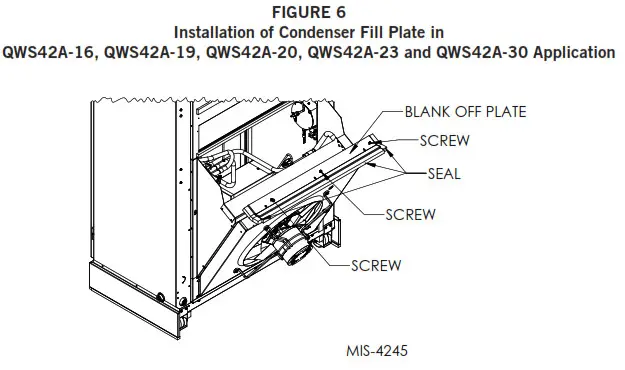
The installation of the QWS42A-16 is similar to the QWS42A with one exception. A condenser fill plate is supplied with QWS42A-16 and is to be attached to the top of the outdoor coil housing on the Q-TEC unit (see Figure 6). To attach the fill plate, remove the three screws on top of the coil section, place the condenser fill plate, and secure with the three screws.
Installation with 19″ Thick Walls
When an application is required on a building with a 19″ wall, a wall sleeve model number QWS42A-19 is required.
The installation of the QWS42A-19 is similar to the QWS42A with one exception. A condenser fill plate is supplied with QWS42A-19 and is to be attached to the top of the outdoor coil housing on the Q-TEC unit (see Figure 6). To attach the fill plate, remove the three screws on top of the coil section, place the condenser fill plate, and secure with the three screws.
Installation with 20″ Thick Walls
When an application is required on a building with 20″ wall, a wall sleeve model number QWS42A-20 is required.
The installation of the QWS42A-20 is similar to the QWS42A with one exception. A condenser fill plate is supplied with QWS42A-20 and is to be attached to the top of the outdoor coil housing on the Q-TEC unit (see Figure 6). To attach the fill plate, remove the three screws on top of the coil section, place the condenser fill plate, and secure with the three screws.
Installation with 23″ Thick Walls
When an application is required on a building with 23″ wall, a wall sleeve model number QWS42A-23 is required.
The installation of the QWS42A-23 is similar to the QWS42A with one exception. A condenser fill plate is supplied with QWS42A-23 and is to be attached to the top of the outdoor coil housing on the Q-TEC unit (see Figure 6). To attach the fill plate, remove the three screws on top of the coil section, place the condenser fill plate, and secure with the three screws.
Installation with 30″ Thick Walls
When an application is required on a building with 80″ wall, a wall sleeve model number QWS42A-30 is required.
The installation of the QWS42A-30 is similar to the QWS42A with one exception. A condenser fill plate is supplied with QWS42A-30 and is to be attached to the top of the outdoor coil housing on the Q-TEC unit (see Figure 6). To attach the fill plate, remove the three screws on top of the coil section, place the condenser fill plate, and secure it with the three screws.
Accessory Items
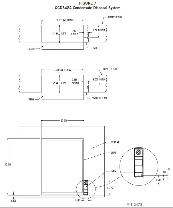
The QCDS48A is a condensate disposal system for use on all Q-TEC air-source equipment. The system consists of a drain box that attaches to the side of the wall sleeve. It has a rear drain that the installer connects to a field-supplied drain tube that will exit the exterior wall adjacent to the wall sleeve. It also includes a provision to connect the indoor drain tube to bypass the condensate from having to travel through the outdoor drain pan.
Bypassing the outdoor drain pan with the indoor condensate can benefit the installation in regards to reducing growth within the lower pan by prohibiting standing water during the warm cooling season. The rear drain box gives further benefit as it allows the Q-TEC unit to be installed or removed without connecting or disconnecting the drain line.
The installation of the QCDS48A requires a recessed area next to the sleeve being built. See Figure 7 for dimensions of the recess for the drain box.
A heated version of the drain box (QCDS48H) is also available for application in climates where the concern of freezing may occur. It includes the rear drain tube that projects through the exterior wall and a self-regulating heater box interior of the drain box and the outlet tube that connects to a 115-volt power supply.
Attachment of Wall Sleeve to Q-TEC Unit
Wall sleeve models QWS42A, QWS42A-16, QWS42A-19, QWS42A-20, QWS42A-23, and QWS42A-30 have two methods of attachment.
Wall sleeves can be attached to the Q-TEC units with brackets supplied with the unit. The side brackets are screwed to the sleeve side and unit side with six screws per side. This method can be used if adequate clearance is available on each side of the unit to drive the screws. If this method is to be used, the studs attached to the sleeve must be removed and discarded.
The other installation method is for installations where there is not adequate clearance to drive the screw into the cabinet sides. The attachment can be made from the inside of the unit. There are two threaded studs extending from the room side of the sleeve to matching holes in the unit rear panel and are secured with a 5/16″ nut on each side (see Figure 3 on page 5).
To use this method, discard the two side mounting brackets. Remove the nuts and washers from the threaded studs and retain them for use later. Remove the lower cabinet door and locate the mating holes in the rear of the cabinet. It may be necessary to clear the holes of the gasket material.
Roll unit into place making sure the unit is aligned from side to side and that the studs have entered the holes in the cabinet back. Push the unit back until the rubber seal on the rear of the cabinet touches the flange on the wall sleeve. Replace the washers and nuts previously removed from the studs. Tighten nuts until there is some compression of the gasket. Replace the lower cabinet panel.
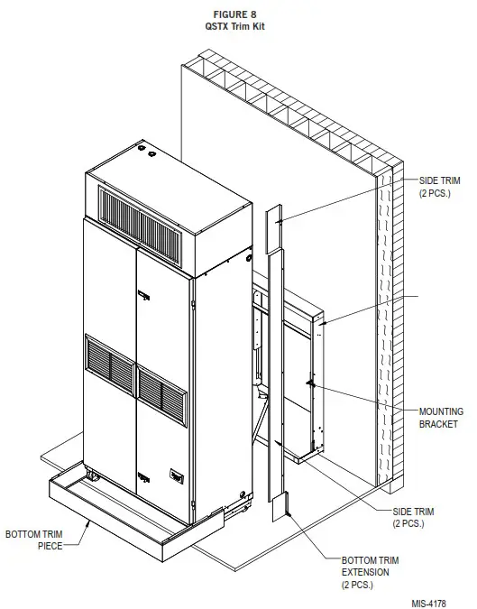
QSTX Trim Kits
During the installation of the unit, a trim kit will be utilized to hide the wall sleeve and give the unit a finished appearance. There is a trim kit that is factory shipped with the unit but it does not cover all installations depending on the thickness of the exterior
wall, or if sleeves of varying depth have been utilized to accommodate other situations.
Reference Table 1 and Figure 8 for additional information as to whether one of the optional accessory trim kits is needed to complete the installation.
| Trim Kit Model | Dimension Suited For |
| Trim pieces factory shipped with QA/QH models | Will fill gaps when the dimension from the back of the Q-TEC unit up to the interior finished wall up to 4′. |
| QSTX42A-X-S10 (Beige) QSTX42A-4-S10 (Buckeye Gray) QSTX42A-7-510 (Vinyl) | Will fill gaps when the dimension from the back of the Q-TEC unit up to the interior finished wall up to 9.5*. |
| QSTX42A-X-S13 (Beige) QSTX42A-4-S13 (Buckeye Gray) QSTX42A-7-S13 (Vinyl) | Will fill gaps when the dimension from the back of the Q-TEC unit up to the interior finished wall up to 12.5′. |
| QSTX42A-X-S16 (Beige) QSTX42A-4-S16 (Buckeye Gray) QSTX42A-7-S16 (Vinyl) | Will fill gaps when the dimension from the back of the Q-TEC unit up to the interior finished wall up to 15.5′. |
Bard Manufacturing Company, Inc.
Bryan, Ohio 43506
www.bardhvac.com
Manual: 2100-289M
Supersedes: 2100-28L
Date: 11-9-20


