Syvecs LTD X10 Gen2 Expander

This document is intended for use by a technical audience and describes a number of procedures that are potentially hazardous. Installations should be carried out by competent persons only.
Syvecs and the author accept no liability for any damage caused by the incorrect installation or configuration of the equipment.
Please Note that due to frequent firmware changes certain windows might not be the same as the manual illustrates.
If so please contact the Syvecs Tech Team for Assistance.
[email protected]
Introduction
The Syvecs X10 expander is a very powerful device for controlling additional I/O (Inputs and Outputs) in an automotive electrical installation. With the use of two CAN controllers, the X10 communicates with master devices to behave as a slave for it, offering the entire I/O compliment to its master device. All our ECU’s (engine control units) will communicate with the X10 with just the use of 2 wires and we have also incorporated logic to allow other manufactures to be able to work with the X10 as well.
4 of the outputs on the X10 are designed to be driven to a high load or low load, making them extremely flexible in what they can offer. These h-bridge outputs can be paired to control external DC motors which are used in drive by wire applications or many other automotive applications.
6 low-side outputs which drive the outputs to ground are also useful for driving solenoids, relays and external devices. These outputs also have the ability to have internal pull-up and fly-back diodes set.
4 DAC (digital-to-analog) outputs are also present on the that convert a binary input number into an analog voltage output. These outputs are useful for sending out a voltage to external device to mirror a sensor signal for example.
While the X10 has 10 inputs not all of them share the same capabilities. 6 of the inputs (AS Inputs) are fully flexible and support frequency detection, SENT decoding, Thermistor (internal 3k pull up) and bipolar operation which means the voltage is monitored above and below the reference ground for use with VR Sensors. The remaining 4 inputs are standard 0-5v ADC inputs.
To finish off the serious I/O compliment that the X10 offers, are 2 x NTK Lambda sensor circuits which allow a sensor to be connected directly and output the oxygen ratio via CAN to the master device.
Specification
Outputs
4 Half Bridge Outputs (Support: Full Bridges, Lows ide or Highs ide Drive) (15Amp Peak (100ms) 8Amp Continuous) 6 Low Side Outputs (12Amp Peak (100ms) 6Amp Continuous) 4 DAC Outputs (-5v to 5v)
Inputs
6 Flexible Inputs supporting frequency, Sent, thermistor, bipolar 4 ADC Voltage inputs 2 NTK Lambda Inputs
Interfaces
USB For Updates and Configuration 2 x CAN 2.0B interface for communication with other controllers or logging systems 1 x Kline Interface
Power Supply
6 to 26V input voltage range Ignition Switch Logic with high current supply
Physical
Waterproof Sealed Automotive Spec -40c to 125c 2 x 34 way Superseal 1.0 connectors 150mm x 150m
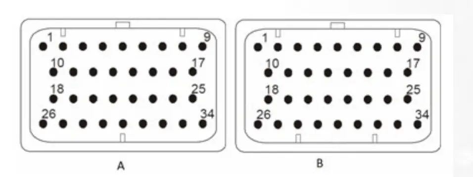
| A | DESCRIPTION | CONNECTOR A | |
| PART NUMBER | 4-1437290-0 | ||
| NOTES: | 34 Way – Key1 | ||
| Syvecs Abbreviations | Pinout | Scal Assignment | Description |
| HBR1 | A1 | Slave*Out1 | H-Bridge Output – Can be driven High or Low |
| PWR ON | A2 | Ignition 12V Signal – Used only for Board Wake up | |
| AS1 | A3 | Slave* AN1 | Flexible Input – 3k Pull Up Available in Software |
| AS3 | A4 | Slave* AN3 | Flexible Input – 3k Pull Up Available in Software |
| AS5 | A5 | Slave* AN5 | Flexible Input – 3k Pull Up Available in Software |
| AS7 | A6 | Slave* AN7 | 0-5V Input Only |
| AV9 | A7 | Slave* AN9 | 0-5V Input Only |
| VBAT1 | A8 | Vbat | 12V Supply – High Current (Required) |
| VBAT1 | A9 | Vbat | 12V Supply – High Current (Required) |
| HBR2 | A10 | Slave*Out2 | H-Bridge Output – Can be driven High or Low |
| KLINE | A11 | Kline or LinBus | |
| AS2 | A12 | Slave* AN2 | Flexible Input – 3k Pull Up Available in Software |
| AS4 | A13 | Slave* AN4 | Flexible Input – 3k Pull Up Available in Software |
| AS6 | A14 | Slave* AN6 | Flexible Input – 3k Pull Up Available in Software |
| AV8 | A15 | Slave* AN8 | 0-5V Input Only |
| AV10 | A16 | Slave* AN10 | 0-5V Input Only |
| 5V | A17 | 5v Output for Sensors | |
| HBR3 | A18 | Slave*Out3 | H-Bridge Output – Can be driven High or Low |
| CAN0L | A19 | Can 0 Low | |
| CAN0H | A20 | Can 0 High | |
| NTK1 ION | A21 | NTK1 Ion Pump (White Wire) | |
| NTK2 ION | A22 | NTK2 Ion Pump (White Wire) | |
| DAC3 | A23 | Slave*Out23 | Digital Output – Can output -5v to +5v volts |
| DAC4 | A24 | Slave*Out24 | Digital Output – Can output -5v to +5v volts |
| ANGND1 / LAM GROUNDS | A25 | Sensor Ground Connection / NTK Ground (Black Wire) | |
| HBR4 | A26 | Slave*Out4 | H-Bridge Output – Can be driven High or Low |
| LSO1 | A27 | Slave*Out5 | Low Side Output |
| LSO2 | A28 | Slave*Out6 | Low Side Output |
| LSO3 | A29 | Slave*Out7 | Low Side Output |
| LSO4 | A30 | Slave*Out8 | Low Side Output |
| LSO5 | A31 | Slave*Out9 | Low Side Output |
| LSO6 | A32 | Slave*Out10 | Low Side Output |
| PWRGND | A33 | Ground Connection – High Current (Required) | |
| PWRGND | A34 | Ground Connection – High Current (Required) |
| B | DESCRIPTION | CONNECTOR B | |
| PART NUMBER | 4-1437290-1 | ||
| NOTES: | 34 Way – Key2 | ||
| VBAT2 | B1 | Vbat | 12V Supply – High Current (Required) |
| VBAT2 | B2 | Vbat | 12V Supply – High Current (Required) |
| N/C | B3 | N/C | |
| N/C | B4 | N/C | |
| N/C | B5 | N/C | |
| N/C | B6 | N/C | |
| N/C | B7 | N/C | |
| N/C | B8 | N/C | |
| N/C | B9 | N/C | |
| 5V | B10 | 5VOut | 5v Output for Sensors |
| N/C | B11 | N/C | |
| N/C | B12 | N/C | |
| N/C | B13 | N/C | |
| N/C | B14 | N/C | |
| N/C | B15 | N/C | |
| N/C | B16 | N/C | |
| N/C | B17 | N/C | |
| ANGND2 / LAM GROUNDS | B18 | Sensor Ground Connection / NTK Ground (Black Wire) | |
| NTK NRNST 1 / CAN3L | B19 | NTK1 NRST Voltage (Grey Wire) / Can 3 Low | |
| NTK NRNST 2 / CAN3H | B20 | NTK2 NRST Voltage (Grey Wire) / Can 3 High | |
| CAN1L | B21 | Can 1 Low | |
| CAN1H | B22 | Can 1 High | |
| N/C | B23 | N/C | |
| N/C | B24 | N/C | |
| N/C | B25 | N/C | |
| PWRGND | B26 | Ground Connection – High Current (Required) | |
| PWRGND | B27 | Ground Connection – High Current (Required) | |
| N/C | B28 | N/C | |
| N/C | B29 | N/C | |
| N/C | B30 | N/C | |
| N/C | B31 | N/C | |
| N/C | B32 | N/C | |
| N/C | B33 | N/C | |
| N/C | B34 | N/C |
General Connections
Connecting Power/Ground
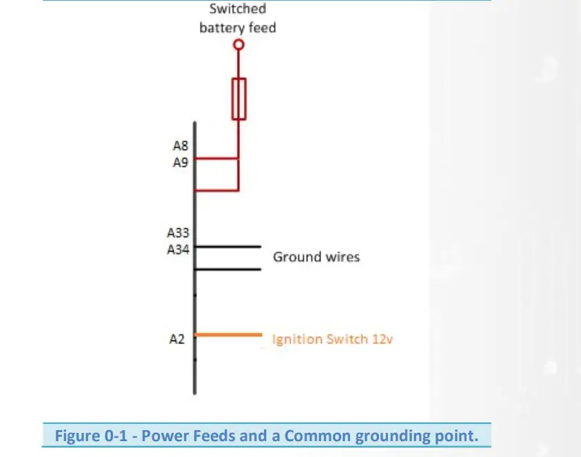
The X10 has 3 power connection points, two of these are high current and can be connected to a fused battery power or switched power source. One of them is Logic Switch / Ignition Switch power and used to switch the power gate so that current is able to flow from the 2 x High current 12v pins into the Device.
If driving motors or solenoids which pull a lot of current then ensure the correct amount of pins are connected. Each pin on the X10 is able to sink around 14 amps of current, so if driving multiple solenoids that pull 20+ amps total, ensure at least two high current 12v pins and two power ground pins are used.
Internally A8/A9 are linked. These can either be used to provide extra current on a supply, or as a way of providing switched power to additional loads through the loom.
Pin A2 (Ignition Sw) is for a 12v low current ignition switch supply to enable the power gate on the X10 internally, this is required on all installations.
Power Grounds are joined internally and the X10 must have at least A33 connected. If driving lots of Low Side outputs then connect A34 also to handle the current loading.
NOTE! Power Grounds are designed to conduct High Current loads – Do not mix Power Grounds with Analogue (AN) Grounds.
Example Schematic
Pin Schedule
| Pin Number | Function | Notes |
| A8 | VBAT1 | Use a fused 12v Switched feed. MUST CONNECT |
| A9 | VBAT1 | Use a fused 12v Switched feed. |
| A33 | Power Ground | Shared Power Ground |
| A34 | Power Ground | Shared Power Ground |
| A2 | Power On | 12v Ignition Switch – Logic Power |
Low Side Outputs
The low side outputs are only able to be driven to ground but offer full pulse width modulation control. The outputs can be used to drive up to 12A Peak / 6A Continuous and can only pull to ground.
Pin Schedule
| Pin Number | Function | Scal Assignment |
| A27 | LSO1 | Assigned to Slave*Out5 |
| A28 | LSO2 | Assigned to Slave*Out6 |
| A29 | LSO3 | Assigned to Slave*Out7 |
| A30 | LSO4 | Assigned to Slave*Out8 |
| A31 | LSO5 | Assigned to Slave*Out9 |
| A32 | LSO6 | Assigned to Slave*Out10 |
Half Bridge Outputs
A H bridge is an electronic circuit that enables a voltage to be applied across a load in either direction. These circuits are often used to drive electronic throttle motor applications to allow DC motors to run forwards and backwards.
Half Bridge Outputs also have full pulse width modulation available and can be driven to 12v or Ground depending on the Output drive type selection.
Output Drive Type:
Full Bridge = Pairs 2 x H-bridge outputs to offer push/pull drive for motor control, I.E HBR1&2 / HBR3&4
H-Bridge – Drives to 12v
Low Side – Drives to Gnd
These outputs can be used to drive up to 15A Peak / 8A Continuous. If you are driving the outputs for high current devices it’s extremely important to ensure the 12v and Ground wire gauge is also capable to handle the current demand. The minimum drive frequency that a H-Bridge can support is 20hz
Pin Schedule
| Pin Number | Function | Scal Assignment |
| A1 | H-Bridge1 | Assigned to Slave*Out1 |
| A10 | H-Bridge2 | Assigned to Slave*Out2 |
| A18 | H-Bridge3 | Assigned to Slave*Out3 |
| A26 | H-Bridge4 | Assigned to Slave*Out4 |
DAC Outputs
A digital-to-analog output (DAC) is a circuit that converts a binary input number into an analog output. These outputs are useful for sending out a voltage to external device to mirror a sensor signal for example.
The outputs can be driven from -5v to +5v and not designed to handle much loading. Maximum 500ma
DAC1 and DAC2 as Default are set to drive the Ion ump for NTK lambda control 1 and 2. DAC 3 and 4 are available. DAC1 and DAC2 can be made available to customers but needs to be ordered this way.
Controlling the outputs is done in Scal – Via a Custom table like Basic Pwm 1. Calibrators should assign the strategy to the correct Slave*Out listed below and then set the frequency for the strategy at 244hz.
0% Duty = -5v
50% Duty = 0v
100% Duty = 5v
Pin Schedule
| Pin Number | Function | Scal Assignment |
| A21 | DAC1/NTK1I | Setup for Ion Pump on Expanders as Default |
| A22 | DAC2/NTK1I | Setup for Ion Pump on Expanders as Default |
| A23 | DAC3 | Slave*Out23 |
| A24 | DAC4 | Slave*Out24 |
Sensor Supply and Grounds
Sensor/ Analogue Grounds (AN Grounds)
Sensors and miscellaneous analogue inputs have their own Ground pins; these grounds must be kept separate from the Power grounds shown in the first section. As there are 2 sensor ground pins you may have to connect multiple grounds to some of the pins if you have more than two sensors.
Pin Schedule
| Pin Number | Function | Notes |
| A25 | ANGND1 | |
| B18 | ANGND2 |
5V Regulated Supply
Sensors and miscellaneous analogue inputs have their own power pins which need a stable power supply, the 5v Regulated outputs are protected and provide a stable/clean 5v which can handle 500ma Maximum.
Pin Schedule
| Pin Number | Function | Notes |
| A17 | 5VOUT1 | |
| B10 | 5VOUT2 |
Input Connections
Input Types
The Syvecs X10 has 10 programmable inputs available and although they are fully configurable in Scal, they are not all the same type of input which means sensors that for example require a pull up, have to be assigned to different types….. Listed below are the 2 types which are available.
Flexible Input – AS Inputs
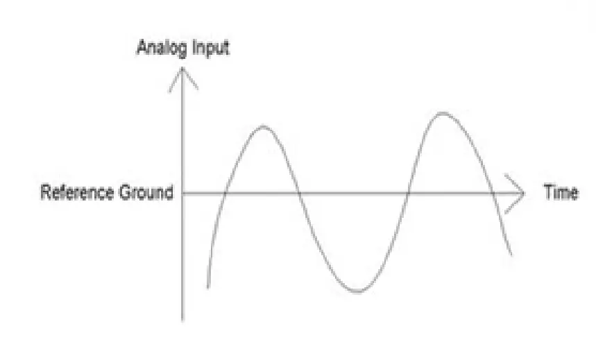
These Inputs are able to swing above and below the reference ground meaning they can see Positive Voltage as well as Negative. Fully Adjusted trigger thresholds for frequency decoding is supported on these pins and they can be used with a vast selection of other sensors from Digital, 0-5v, SENT, Thermistor and Magneto Resistive
Example of sensors normally used on these Inputs are:
- Reluctor Crank and Cam Sensors / ABS Sensors for wheel speed
- Hall Sensors
- Map Sensor
- Temperature Sensor
- SENT Sensors
Bipolar inputs are not just limited to the above they can also be used for any sensor that outputs 0- 5volts. They are also able to provide a 3k Pull-up through Scal when the Input Type is set as Thermistor
| Pin Number | Input | Scal Assignment |
| A3 | AS1 | Slave*An01 |
| A12 | AS2 | Slave*An02 |
| A4 | AS3 | Slave*An03 |
| A13 | AS4 | Slave*An04 |
| A5 | AS5 | Slave*An05 |
| A14 | AS6 | Slave*An06 |
Voltage Inputs – AV Inputs
These Inputs are able to sense a Voltage level but not offer Frequency detection
Example of sensors which normally use on these Inputs are:
- Manifold Pressure sensors
- Throttle Positions
- Oil Pressures
Voltage Inputs are not just limited to the above they can also be used for any sensor which outputs a 0-5volt signal. They Do NOT have an internal 3k software configurable pull up like the AS Inputs for thermistor sensors. This needs to be set externally in the loom.
| Pin Number | Input | Scal Assignment |
| A6 | AV7 | Slave*An7 |
| A15 | AV8 | Slave*An8 |
| A7 | AV9 | Slave*An9 |
| A16 | AV10 | Slave*An10 |
Sensor Schematics – Examples
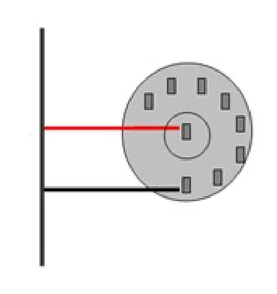
Speed Sensor – Magnetic Type
Example Schematic
Pin Schedule
| Pin Number | Function | Notes |
| A25 | ANGND1 | May be shared with multiple sensors |
| A4 | AS3 | Can use Inputs AS1-12 or AV13-20 with External pullup |
Manifold Pressure Sensor (MAP)
Example Schematic
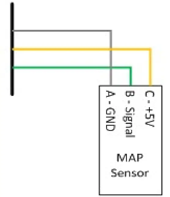
Pin Schedule
| Pin Number | Function | Notes |
| A25 | ANGND1 | May be shared with multiple sensors |
| A17 | 5VOUT1 | Regulated sensor power supply |
| AV10 | AV10 Input | Any Input can be used |
SENT Sensor
The X10 has the ability to work with 12 SENT protocol sensors on AS1-12. Calibrators need to connect to the X10 via USB with Scal and change the Input selection for the desired AS input to SENT (See page 17) .The SENT Protocol decoded output will then populate the slave data into the ECU on the AN input selected
Example Schematic
Pin Schedule
| Pin Number | Function | Notes |
| A25 | ANGND1 | May be shared with multiple sensors |
| A17 | 5VOUT1 | Regulated sensor power supply |
| A3 | AS1 Input | Need to use AS1-6 and AS11-16 |
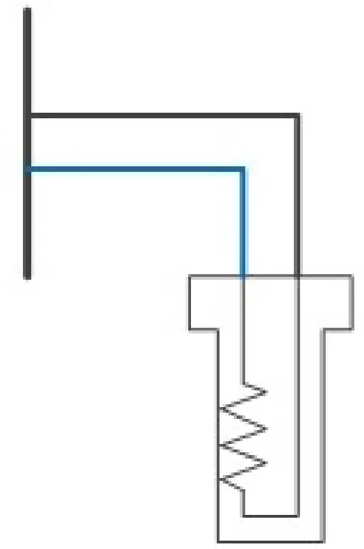
Coolant Temperature Sensor (CTS)
Example Schematic
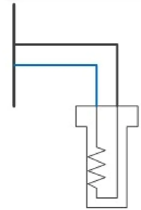
Pin Schedule
| Pin Number | Function | Notes |
| A25 | ANGND1 | May be shared with multiple sensors |
| A4 | AN3 | Can use Inputs AS1-12 or AV13-20 with External pullup |
Inlet Air Temperature Sensor (IAT)
Example Schematic
Pin Schedule
| Pin Number | Function | Notes |
| A25 | ANGND1 | May be shared with multiple sensors |
| A4 | AN3 | Can use Inputs AS or AV with External pullup |
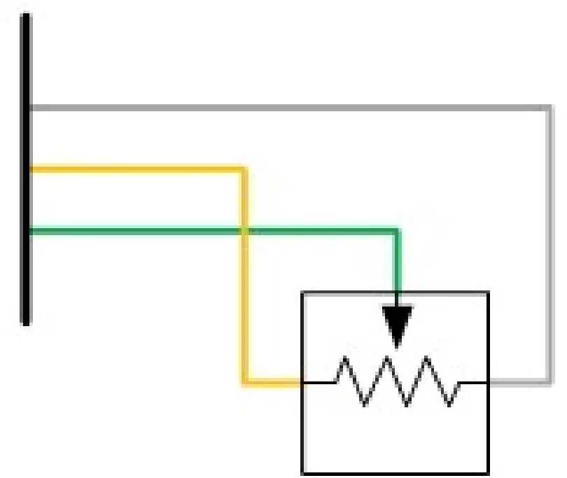
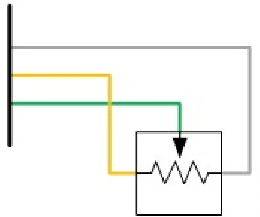
Calibration Switches
Example Schematic
Pin Schedule
| Pin Number | Function | Notes |
| A25 | ANGND1 | May be shared with multiple sensors |
| A12 | AN2 | Can use Inputs AS or AV with External pullup |
Digital Oil Level Sensors
Need to connect to the X10 via USB with Scal and Change the Input Selection for the desired AS input to Pulse Oil Level. The output will then populate the slave data into the ECU
Example Schematic
Pin Schedule
| Pin Number | Function | Notes |
| A25 | ANGND1 | May be shared with multiple sensors |
| A17 | 5VOUT1 | Regulated sensor power supply |
| A3 | AS1 Input | Need to use AS1-6 and AS11-16 |
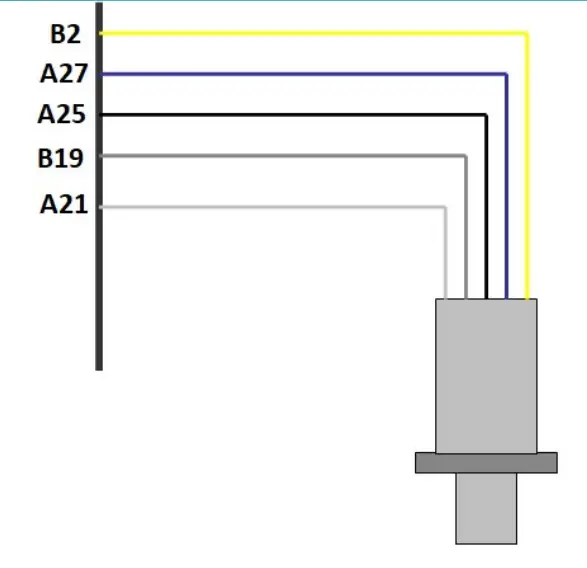
Wideband Lambda Sensors
The Syvecs X10 has the ability to drive two NTK L1H1/L2H2 Wideband Lambda sensors without the use of external hardware. Please see wiring and fitting information below
Example Schematic
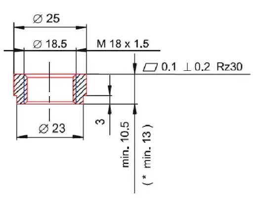
Mounting recommendation
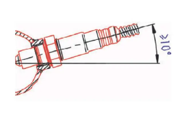
Recommended materials for the mating thread in the exhaust pipe *: THexagon > 600°C or TG as > 930°C
NTK L2H2
Lambda Sensor assignments in Scal needs to be set to Slave* AN21 for Lambda 1 and Slave* AN22 for Lambda 2.
When an X10 is connected to an S7, users can change the Lambda type via Sensors – Lambda – Sensor Type. This needs to be set to NTK.
With the S6, S8, S12 or other brands of ECU, the lambda configuration map is not present and as default the X10 will run as NTK Mode.
Lambda Heater Function In Scal can be assigned to any Output on the X10
Lamda1
| Lambda Pin Number | Colour | Name | X10 Pin |
| 1 | Yellow | Heater | 12v |
| 2 | Blue | Heater Drive | Any LSO or HBR Output |
| 6 | Grey | Nernst Cell Voltage | B19 |
| 7 | White | Ion Pump Current | A21 |
| 8 | Black | Signal Ground | A25 or B18 |
Lambda2
| Lambda Pin Number | Colour | Name | X10 Pin |
| 1 | Yellow | Heater | 12v |
| 2 | Blue | Heater Drive | Any LSO or HBR Output |
| 6 | Grey | Nernst Cell Voltage | B20 |
| 7 | White | Ion Pump Current | A22 |
| 8 | Black | Signal Ground | A25 or B18 |
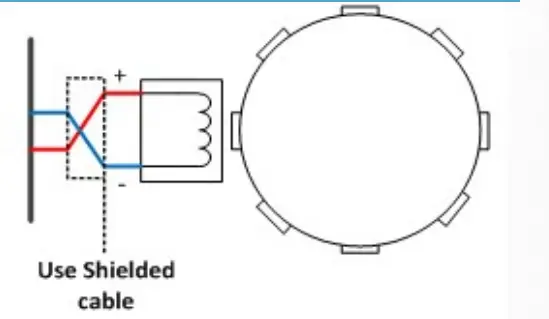
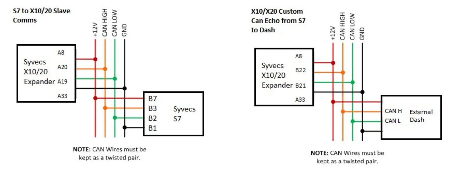
CAN Bus
Common Area Network Bus (CAN Bus) is a widely used data interface common used in many cars and aftermarket accessories (such as Data loggers and Dashes). Data is sent using the High and Low wires, which are maintained as a twisted pair.
The X10 as default has 2 x CAN bus interfaces:
CAN0 is used for expander communications with the Syvecs Engine ECU. (120ohm Termination Resistor)
CAN1 is available for generic use but can be used also for bridging the custom can data from CAN0 to external dashboards. This is enabled as default for Syvecs expanders, where the custom can data from the Syvecs Engine Ecu will be passed through the expander CAN0 to CAN1. (120ohm Termination Resistor)
Example Schematics
| Pin Number | Function | Notes |
| A19 | CAN0 LOW | Ensure wires are twisted pair. |
| A20 | CAN0 HIGH | Ensure wires are twisted pair. |
| B21 | CAN1 LOW | Ensure wires are twisted pair. |
| B22 | CAN1 HIGH | Ensure wires are twisted pair. |
PC Connection – SCAL
The X10 has a calibration stored onboard to maintain settings of the X10 hardware. In order for the X10 to work it must have a valid calibration present in the device and when shipping from the factory a default cal is loaded to ensure it works out of the box. Calibrators who wish to enable an Input to work in SENT decoding or setup custom CAN transmit will need to connect live to the X10.
A USB-C port is found at the back of the X10 which is IP67 sealed. Use a USB-C to USB-A male/male cable to connect the X10 to the computer. The S-Suite software can be downloaded from below.
https://www.syvecs.com/software/
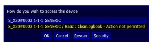
After running the SSuite installer, open the program called SCal and click Device – Connect
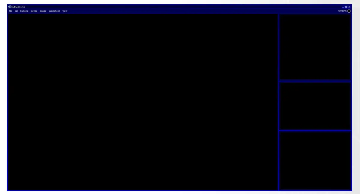
A X10 device will be found as shown below, press Ok to proceed
 \
\
The connected green icon should now be present in the top right and all the voltages/temps from onboard the X10 are listed on the right hand side.
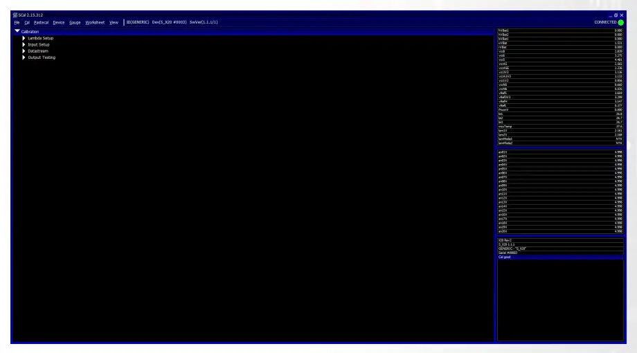
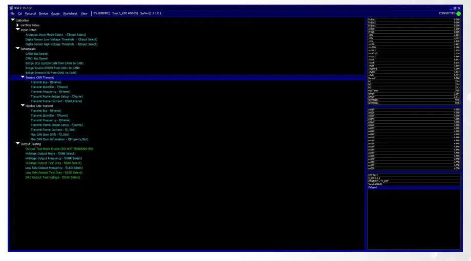
Calibrators now have the ability to change the Input setup for each AN Input, setup custom DataStream CAN options or use the output testing (see page 18).
Press F1 for help on a map and remember that:
Green Maps – Live Adjustable
Blue Maps – Require programming to set
Output Testing
The X10 outputs can be tested live with our Syvecs – Scal program and information on connecting to the unit can be found in the PC Connection section of the manual. After connecting to the expander via USB, users will see an area at the bottom of the calibration tree called output testing.
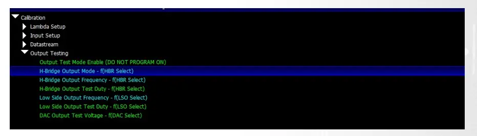
Here users are able to test the functions of each output by itself without the need for any master/slave CAN communication.
NOTE: H-Bridge Output Mode / H-Bridge Output Frequency / Low Side Output Frequency maps must be set and programmed onto the device for the output testing logic of these outputs to apply. You cannot change these maps when Output Test Mode Enable is enabled.
Green Maps – Live Adjustable
Blue Maps – Require programming to set
Set a frequency you wish the outputs to be driven at in H-Bridge Output Frequency and Low
Side Output Frequency. Next set the H-Bridge Output Mode and Device – program the X10.
Output Test Mode Enable can then be enabled.
Now you can then set a duty for each output to be driven in H-Bridge Output Test Duty and Low Side Output Test Duty. These maps can be adjusted live.
If H-Bridge Output Mode map is set on Full Bridge, the paired outputs used in the full bridge individually set the drive direction.
For example: Motor is wired to HBR1 and HBR2, Output Mode is set to Full Bridge on HBR1 and 2.
Increasing Duty on HBR1 output duty cell will cause the full bridge to drive the HBR1 output positive and the HBR2 output negative.
DAC Output Test Voltage is a live map which you can set the voltage that DAC1 -4 are driven at in Output test mode.

 Owner's Manual")


