
Lumineux UK 430156-SD Rutland Bulkhead Instruction Manual
READ THESE INSTRUCTIONS THOROUGHLY BEFORE INSTALLATION KEEP THESE INSTRUCTIONS FOR FUTURE REFERENCE.
IMPORTANT:
This product must be installed by a qualifi ed electrician or competent person, and in accordance with current building and IET wiring regulations.
BOX CONTENTS
This lighting fi xture has been properly packed to avoid damage during transit. Before commencing with the installation carefully inspect the luminaire to confi rm there is no damage. DO NOT INSTALL if any damage has occurred to the fi xture or any of its components.
- Light Fitting
- Instruction Manual
- Fixing Kit
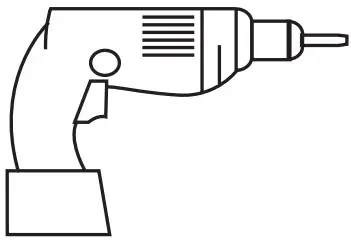
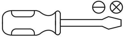
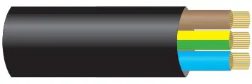
TOOLS REQUIRED
- Drill

- Screwdriver

- Cable

Manby Business Park, Manby, Lincolnshire, LN11 8UT Lumineux is a B&T Associates Ltd company
PLEASE READ THESE INSTRUCTIONS BEFORE INSTALLATION.
![]() WARNING: Risk of electric shock! Isolate the mains power before proceeding.
WARNING: Risk of electric shock! Isolate the mains power before proceeding.
- Turn off the mains power before performing inspections, installation, or removal
- Verify that the supply voltage is correct by comparing it with the luminaire label information
- It is the installers responsibility to ensure installation is suitable for the total load of the luminaire(s). The supply cable, fuses/circuit brakers must be correctly rated for the electrical load and considering for any transient inrush currents that may occur
- Do not perform insulation strength or resistance tests on installed luminarie(s) connected
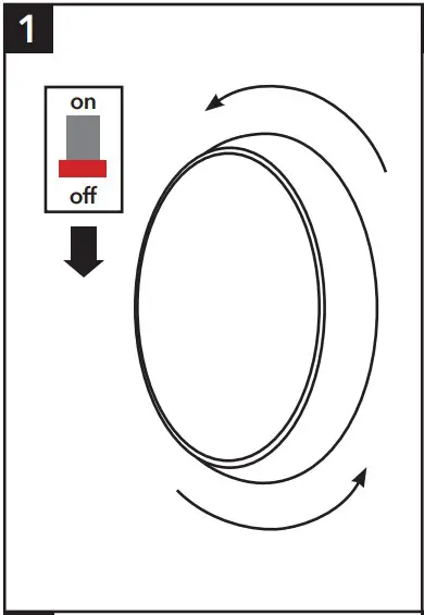
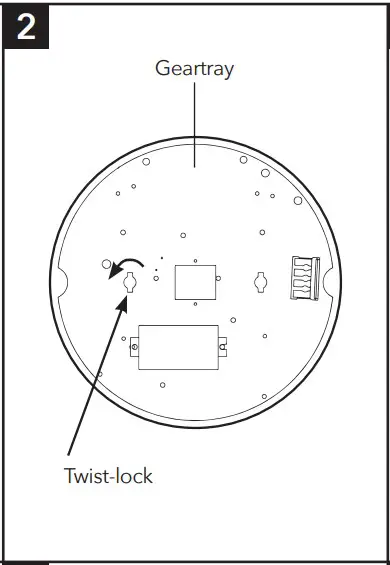
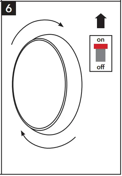
- Remove the diffuser by gently twisting anti-clockwise

- Twist the locking tab to loosen and remove the geartray.
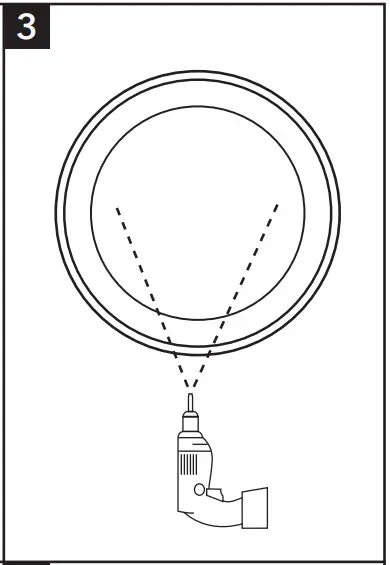
- Drill appropriately sized holes through your chosen mounting points in the base
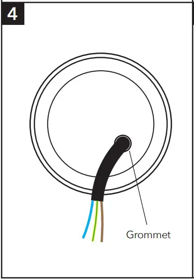
- Install grommet to your chosen cable entry and pierce, making a hole just large enough to make a tight fi t around the incoming mains cable. Carefully thread cable through grommet and secure fi tting in place

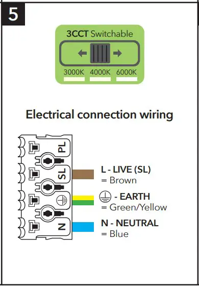
- Wire as per diagram (5). Select colour temperature (Please see overleaf for instructions on how to set all sensor versions and emergency)
- Replace the geartray and twist the locking tab to secure in place, then refi t the diffuser and then re-connect the mains supply
DISPOSAL
Disassembly instructions for end of life disposal available on website. Disposal of Electronic Equipment WEEE Directive 2002/96/EC This product falls within the scope of the Waste Electrical & Electronic
Equipment Directive (WEEE), which means the product should not be disposed of as normal household waste. Please recycle where facilities exist or check with your
Local Authority. RoHS – All components and materials used in this product are RoHS 2002/95/EC compliant.
Specifications may change from time to time. The information contained in this leaflet is for guidance only and should not be considered as always accurate and should be treated as not representative.
WARRANTY
This luminaire is warranted for a period of 5 years from the date of purchase**. The backup battery pack in the emergency version is warranted for a period of 24 months. The warranty could be invalidated should the light fitting not be installed according to these instructions, outside the scope of the specification or the product has been altered or tampered with in any way. Please see website for terms and conditions.
PRODUCT TEMP SPECIFICATION
- Standard -20 to +40ºC
- Emergency 0 to +30ºC
- Revision 2 – October 2022
MICROWAVE SENSOR SETTINGS
This determines the effective range of the motion.
Note that reducing the sensitivity will also narrow the detection range.
Hold Time Duration: This determines the time the fitting remains at 100% illumination following motion detection.
Daylight Setting: This setting holds off the 100% light output should there be sufficient daylight.
STANDARD ON/OFF SENSOR
| DETECTION AREA | HOLD TIME | DAYLIGHT SENSOR | ||||||||||||
| 1 | 2 | 3 | 4 | 5 | 6 | 7 | 8 | 9 | ||||||
| I | ON | ON | ON | 100% I | ON | ON | ON | 5s I | ON | ON | ON | 2Lux | ||
| II | – | ON | ON | 75% II | – | ON | ON | 30s II | ON | ON | – | 10Lux | ||
| III | ON | – | ON | 50% III | ON | – | ON | 90s III | – | ON | – | 25Lux | ||
| IV | – | – | ON | 25% IV | – | – | ON | 3min IV | ON | – | – | 50Lux | ||
| V | – | – | – | 10% V | ON | ON | – | 20min V | – | – | – | Disable | ||
| VI | – | – | – | 30min | ||||||||||
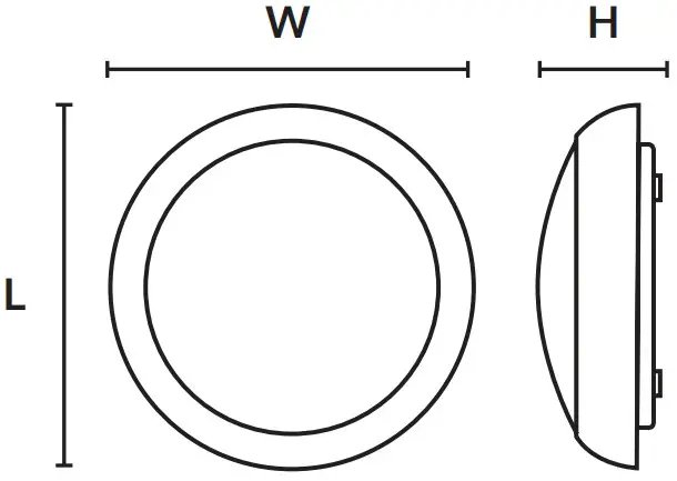
RUTLAND BULKHEAD DIMENSIONS
| Part No. Description | Watts | L (mm) | W (mm) | H (mm) | Weight |
| Rutland430156 3CCTBulkhead | 12W | 330 | 330 | 110 | 0.8Kg |
STEP DIM DRIVER SETTINGS
DETECTION AREA
| 1 | ||
| I | ON | 100% |
| II | – | 50% |
HOLD TIME
| 2 | 3 | |||
| I | ON | ON | 5S | |
| II | ON | – | 90S | I |
| III | – | ON | 3min | II |
| IV | – | – | 10min | III |
DAYLIGHT SENSOR
| 4 | 5 | ||
| I | ON | ON | Disable |
| II | ON | – | 30 Lu |
| III | – | ON | 15 Lux |
| – | – | 5 Lux |
STAND-BY PERIOD
| 6 | 7 | ||
| I | ON | ON | 0s |
| II | ON | – | 30s |
| III | – | ON | 10min |
| IV | – | – | +∞ |
STAND-BY DIM LEVE
| 8 | ||
| I | ON | 10% |
| II | – | 25% |
* OUTPUT CURRE
| S1 | S2 | S3 | |
| 450mA | ON | ON | ON |
| 400mA | ON | – | ON |
| 380mA | – | – | ON |
| 350mA | – | ON | – |
| 320mA | ON | – | – |
| 300m | – | – | – |
* Do not change output current unless instructed or this will void warranty
| Installation Engineers Contact Details: | Luminaire Reference / Location | |
| Name: | Tel: | |
| Luminaire Details: | Full Recharge Duration 24 Hours | Emergency Duration 3 Hours | Lamp Type LED |
| ROUTINE TEST RECORD | ||||||||||
| Type Test | Year 1 | Year 2 | Year 3 | Year 4 | Year 5 | |||||
| Signed | Date | Signed | Date | Signed | Date | Signed | Date | Signed | Date | |
| Functional 1 | ||||||||||
| Functional 2 | ||||||||||
| Functional 3 | ||||||||||
| Functional 4 | ||||||||||
| Functional 5 | ||||||||||
| Functional 6 | ||||||||||
| Functional 7 | ||||||||||
| Functional 8 | ||||||||||
| Functional 9 | ||||||||||
| Functional 10 | ||||||||||
| Functional 11 | ||||||||||
| 3hr Duration 12 | ||||||||||
Wiring instructions for units equippedan with EMERGENCY function
Emergency lighting luminaries must be installed and maintained in accordance with the emergency lighting standard BS 5266-1
- Connect incoming earth cable to ‘Earth’ terminal on connector block.
- Connect incoming neutral cable to ‘Neutral’ terminal on connector block.
- For the emergency unit to work correctly, please ensure that an uninterrupted permanent live feed is present and is connected directly to the ‘Permanent Live’ terminal of the mains terminal block. Please ensure there are no switches, PIRs etc within the permanent live feed, constant switching of the emergency pack could result in premature battery failure.
- Connect incoming switched live cable to the terminal marked “Switched Live”
NOTE: If there is no switch live feed and the unit has a microwave sensor, simply bridge across from the “Permanent Live” to the Switch Live” on the mains terminal block. - There should be a loose flying lead connected to the battery. This needs to be attached to the flying lead from the emergency control unit.
- Following power up the green LED indicator should illuminate to indicate charging. If power to the unit is disrupted or isolated, the unit indicating green LED will switch off, triggering the emergency LEDs to illuminate.
- Please allow 24 hours charge before first emergency tes

This product contains a light source of energy efficiency Class E.
Technical Helpline: +44 (0)1507 328031