![]() Tech RFGM Series RF Power Modules
Tech RFGM Series RF Power Modules
User Manual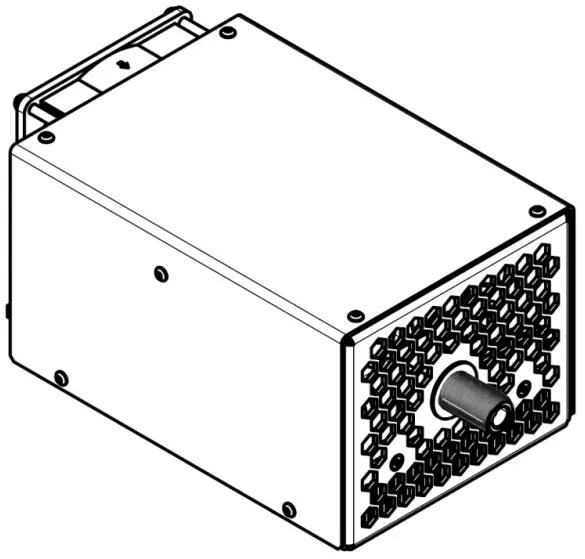
RFGM Series RF Power Modules
Warning! This equipment may be dangerous.
Please read the entire user manual carefully before using the product.
Description
RFGM is a series of RF power modules providing at its output high voltage sine wave in a single frequency mode from radio-frequency range. Output frequency is selectable at the moment of order from sub-megahertz range to 81.36MHz, factory fixed. Output power varies from 300W to 1500W in dependence on model. See also How to order? section on page 12 for details and list of models available.
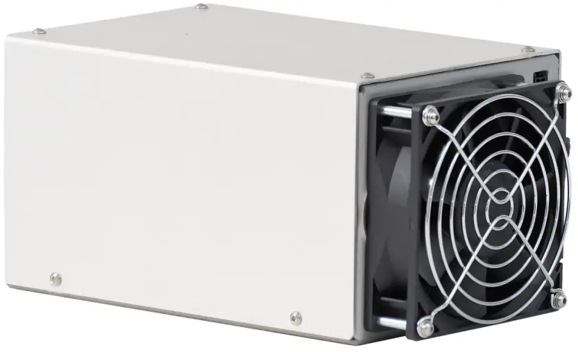
All modules are cooled with a built-in fan. Rotation speed of the fan in controlled by module’s MCU.
Please note, the modules are not a stand-alone solution and for proper operation they need external sources of high (300-500VDC) and low (24VDC) voltage of the appropriate power. A typical application schema is given below: 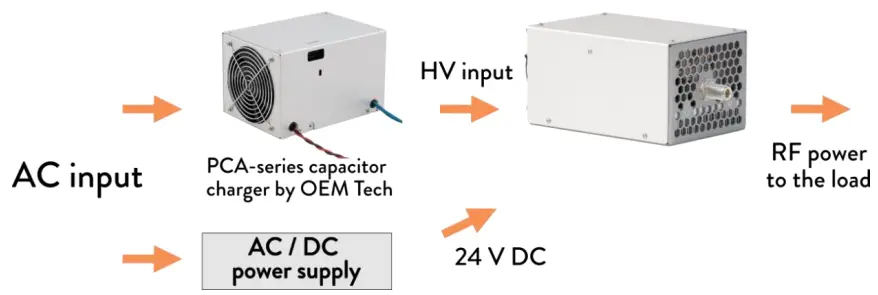 An average output power of the module can be regulated in two different ways:
- by varying the input DC voltage (an output power of RFGM module increases with the rise of its input voltage)
- by multi-kilohertz PWM of the output (set either by Power control signal or via RS-485). An average output power in this case is linear with duty cycle.
A power combining of multiple modules is possible on request. An output power obtained in this case can reach 3000W and beyond.
RFGM-series power modules can be controlled in two different ways – either via
RS-485 digital interface or, alternatively, via signals of INTERFACE connector.
Appearance and layout
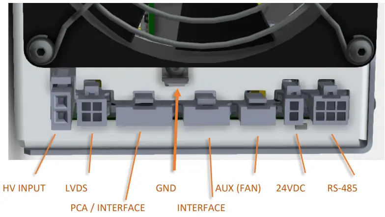
 Side 1: Inputs and interfaces
Side 1 contains high voltage input to the module (300VDC-500VDC), low voltage input to the module (24VDC), all the interfaces connectors (both digital and analogue) as well as a grounding stud 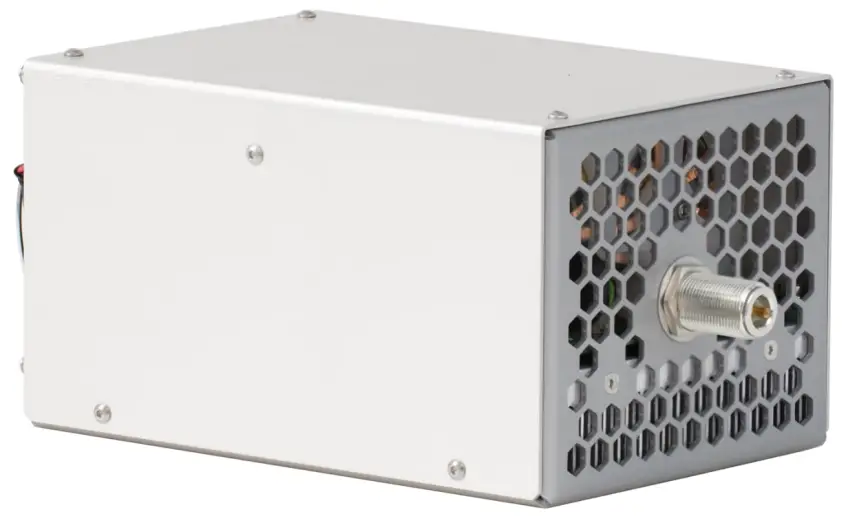 Side 2: RF Output
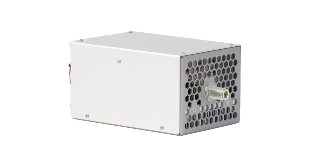
Side 2 contains RF output only
Connectors / Pins / Interface signals
 RS-485: Molex 43045-0601
| Designation | Pin | Description |
| RS485 B | 2 | Inverting Driver Output/Receiver Input |
| RS485 A | 3 | Non-inverting Driver Output/Receiver Input |
| RS485 COMM | 4 | Common wire for ‘RS485 A’ and ‘RS485 B’ signals |
| RS485 SCREEN | 5 | Ground point for electrical screen of RS485 cable (N/C by default, available on request) |
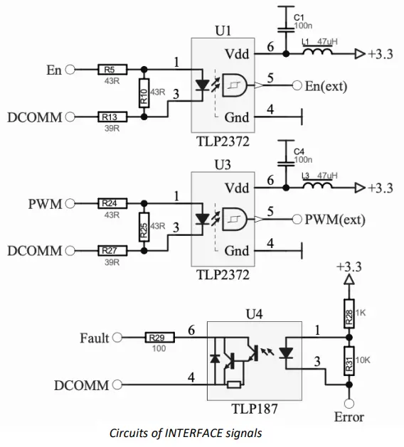
INTERFACE: Molex 43650-0400
| Designation | Pin | Description |
| Fault | 1 | Logic output, open collector, active low – indicates either an internal failure of the module or that the module isn’t ready to work Once Fault occurs, ‘Enable’ should be reactivated to reset the Fault state |
| Interface return (DCOMM) | 2 | Common wire for ‘Enable’, ‘Power control’ and ‘Fault’ signals |
| Enable (En) | 3 | Logic input, 5V TTL/CMOS, active high – general enable to the module Input impedance – approx. 120 Ohm |
| Power control (PWM) | 4 | Logic input, 5V TTL/CMOS , active high – module generates RF power when both ‘Enable’ and’ Power control’ signals are ‘high’ state Switching of Power control signal with multi-kilohertz frequency can be used to adjust the average output power of RFGM module Input impedance – approx. 120 Ohm Nominal frequency range from 1 kHz to 10 kHz. Duty cycle limitations are as follows: ‘1’ state – 3 us min ‘0’ state – 10 us min |
 | ||
PCA/INTERFACE: Molex 43650-0500
Capacitor charger of PCA-series is to be connected here.
| Designation | Pin | Description |
| Interface return | 1 | See user manual of PCA-series capacitor charger for the detailed signal description |
| Fault | 2 | |
| Inhibit | 3 | |
| Voltage program | 4 | |
| 15V DC | 5 |
AUX (FAN): Molex 43650-0301
An auxiliary connector exclusively used to connect the fan cooling RFGM module.
24VDC: Molex 43045-0202
Low voltage to the module
| Designation | Pin | Description |
| +24VDC | 1 | 24VDC power supply connection Maximal current consumption – 1A |
| COMM 24VDC | 2 |
HV INPUT: Molex 2601-3114
High voltage (up to 500VDC) to the module
| Designation | Pin | Description |
| HV | 1 | High voltage power supply connection Maximal input voltage – 500VDC Nominal input voltage is model dependent |
| COMM HV | 2 |
LVDS: Molex 43045-0401
LVDS input is used either to run module in external synchronization mode or to organize a parallel connection of multiple modules. By default, LVDS connector in non-functional, but available on customer’s request (see also How to order? section, p.12).
| Designation | Pin | Description |
| +IN for ‘slave’ modules +OUT for ‘master’ modules | 1 | Logic input, LVDS – external oscillator non-inverting input (output) |
| -IN for ‘slave’ modules -OUT for ‘master’ modules | 2 | Logic input, LVDS – external oscillator inverting input (output) |
| LVDS COMM | 3 | Common wire for external oscillator input (output) |
| LVDS SCREEN | 4 | Ground point for electrical screen of external oscillator cable (N/C by default, available on request) |
GROUND: 6.35mm Quick-Connect terminal, male
Protective grounding should be organized by using this stud.
RF OUTPUT: N-TYPEN
N-TYPE RF connector by Amphenol (5/8-24 thread, female).
RF Output return is interconnected to RFGM chassis.
Grounding policy
The following considerations should be taken into account:
- RF Output return is interconnected to RFGM chassis.
- Due to safety reasons, RFGM chassis must be protectively grounded.
Specifications
ELECTRICAL
| General | |
| Product | RF power module |
| Schematics | Class E power generator |
| Input | |
| HV Input | DC voltage, regulated, 300V-500V max (model dependent) |
| HV power consumption | 2000W max (model dependent) |
| LV Input | 24VDC |
| LV current consumption | 1A max |
| Output | |
| Load impedance | 50 Ohm |
| Frequency | 6.78MHz, 13.56MHz, 27.12MHz, 40.68MHz, 81.36MHz (other on request), fixed, selectable at the moment of order |
| Peak power (WMAX) | 1500W max (model dependent) |
| Duty cycle | 0-100% |
| Average power | 0-WMAX |
| Output connector | N-TYPE RF connector by Amphenol (5/8-24 thread) |
| Interfaces | |
| Analogue | + (a set of TTL signals) |
| Digital | + (RS-485 by default, other on request) |
| Other | |
| Protections | – Overtemperature protection – Short circuit tolerant – Open circuit tolerant (shorttime) |
| Safety features | Power monitors Capacitive coupling of the output |
| Grounding | Output return is connected to the chassis |
| Cooling | Forced air cooling with built-in fan |
| Power combining of multiple modules | + (two modules can be connected in master-slave mode; for connection of three and more modules an appropriate controller is needed; an appropriate power combiner is needed in all cases) |
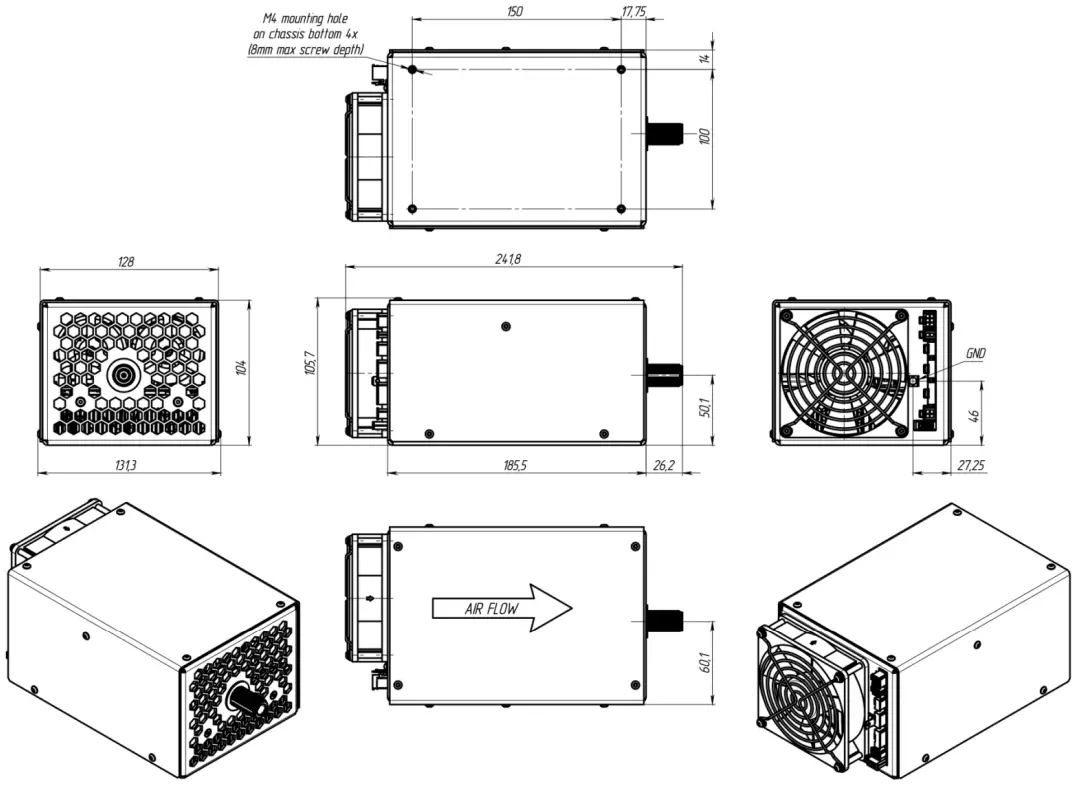
MECHANICAL
| Dimensions | See dimensional drawing below |
| Weight | Approx. 2.5 kg |
Dimensional drawing
How to order?
RFGM-XXX-YYY-ZZ, where:
- XXX means the working frequency of the module; the most standard frequencies are 6.78MHz, 13.56MHz, 27.12MHz, 40.68MHz and 81.36MHz, other frequencies are available on request
- YYY means the maximal output power of the module; typically the maximal power is in range from 300W to 1500W, other output power values can be considered on request
- ZZ means the type of the module; none or 0 – stand-alone module (not suitable for master-slave operations)
M – master (master unit for master-slave operations)
S – slave (master unit for master-slave operations
Master-slave connection of two modules allows to increase the maximal output power twice and achieve 1000W to 3000W power levels.
Examples (the most popular modifications):
| Frequency | Output power | Description | Part numbers |
| 0.5-4MHz | Up to 1500W | Easily available as modifications of 6.78MHz model All parameters are configurable | Custom |
| 6.78MHz | 800W | Suggested HVDC source – PCA-10-300V-PD | RFGM-6.78-800 |
| 1500W | Suggested HVDC source – PCA-20-500V-PD | RFGM-6.78-1500 | |
| 13.56MHz | 800W | Suggested HVDC source – PCA-10-300V-PD | RFGM-13.56-800 |
| 1500W | Suggested HVDC source – PCA-20-500V-PD | RFGM-13.56-1500 | |
| 27.12MHz | 500W | Suggested HVDC source – PCA-10-300V-PD | RFGM-27.12-500 |
| 1000W | Suggested HVDC source – PCA-10-300V-PD for 800W operations and below or PCA-20-500V-PD for 1000W operations | RFGM-27.12-1000 | |
| 40.68MHz | 500W | Suggested HVDC source – PCA-10-300V-PD | RFGM-40.68-500 |
| 81.36MHz | 300W | Suggested HVDC source – PCA-10-300V-PD | RFGM-81.36-300 |
Other modifications with different output power, operating frequency as well as other parameters are available on request.
Appendix 1. Software description
Software tool “RFUnit Control”, a simple utility for Microsoft Windows operating system, is supplied with every RFGM-series module to control it.
It monitors:
- Power switch temperature
- Fan speed
- Output power
- Modbus server counters
- Fault input
and also allows to control “Enable” and “PWM”.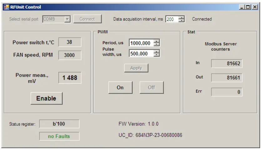 Operations (via RS-485 interface)
- Connect RFGM module to low voltage power supply, high voltage power supply, to the load and to your PC
- Run the software, apply low voltage and high voltage to RFGM module
- Select serial port, where the module is connected to, press Connect button
- Press Enable button to provide power to the output
Appendix 2. RS-485 interface description
RFGM-series modules can be remotely controlled through RS-485 serial bus by using Modbus RTU protocol
Communication parameters (factory fixed):
| Parameters | Factory settings |
| Protocol | Modbus RTU |
| Address | 1 |
| Baud rate | 115200 |
| Parity | E,8,1-Even Parity |
| Checksum | Modbus RTU CRC-16 |
Embedded Modbus RTU server supports following functions:
| Function code | Description |
| 03 (0x03) | Read Multiple Registers |
| 16 (0x10) | Preset Multiple Registers |
It is possible to use different software for RS-485 digital interface testing – for example RFUnit Control (an utility, provided by OEM Tech, see also Software description section), QModBus (a free Modbus master application) or your own
Modbus Register Mapping:
| Address (Base 0), decimal | R/W | Description | Data format |
| 1 | R | Firmware Version | Unsigned integer 16 bits. Example: 10203 means version 1.2.3 |
| 2 | R | Status | Unsigned integer 16 bits: Bit 0: 0-disabled, 1-enabled Bit 1: 0-PWM off, 1-PWM on Bit 2: 0-FAN control off, 1-FAN control on Bit 8: 0-No Fault, 1-Fault |
| 3 | R | FAN rotation speed | Unsigned integer 16 bits. 0÷4800 RPM |
| 6 7 | R | Digitized Power monitor signal, mV | Single precision float (IEEE754), little endian: Address 6 – low 16 bits Address 7 – high 16 bits |
| 8 | R | Power switch temperature, °C | Signed integer 16 bits. -50 ÷ 150 |
| 9 | R/W | FAN speed control: PWM duty cycle, % | Unsigned integer 16 bits. 0 ÷ 100 |
| 10 11 | R | Modbus server: received requests counter (reset on power up) | Unsigned integer 32 bits, little endian: Address 10 – low 16 bits Address 11 – high 16 bits |
| 12 13 | R | Modbus server: transmitted answers counter (reset on power up) | Unsigned integer 32 bits, little endian: Address 12 – low 16 bits Address 13 – high 16 bits |
| 14 15 | R | Modbus server: error counter (reset on power up) | Unsigned integer 32 bits, little endian: Address 14 – low 16 bits Address 15 – high 16 bits |
| 16 17 | R/W | PWM output active state (‘1’) duration, µs | Single precision float (IEEE754), little endian: Address 16 – low 16 bits Address 17 – high 16 bits |
| 18 19 | R/W | PWM period, µs | Single precision float (IEEE754), little endian: Address 18 – low 16 bits Address 19 – high 16 bits |
| 20 | W | Switch On function | Unsigned integer 16 bits: Bit 0: 0-has no effect, 1-enable Bit 1: 0-has no effect, 1-PWM on Bit 2: 0- has no effect, 1-FAN control on |
| 21 | W | Switch Off function | Unsigned integer 16 bits: Bit 0: 0-has no effect, 1-disable Bit 1: 0-has no effect, 1-PWM Off Bit 2: 0- has no effect, 1-FAN control off |
| 36 37 38 39 40 41 | R | Embedded microcontroller’s Device ID | 96-bit unique microcontroller ID |
Appendix 3. Insulation diagram (safety diagram)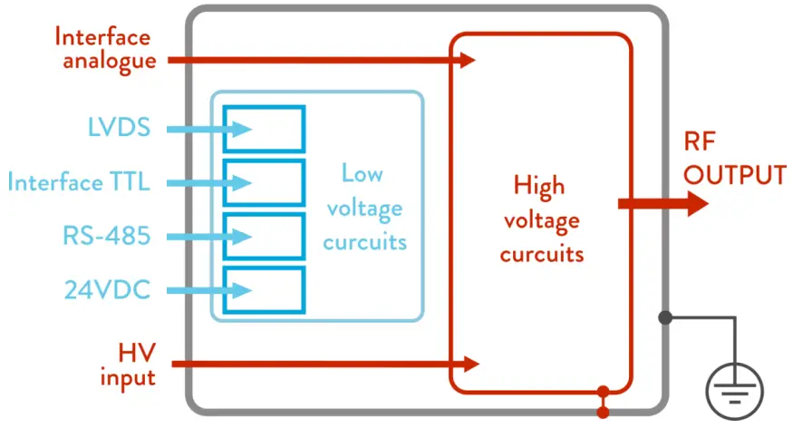
Gray – chassis (must be protectively grounded)
Red – high voltage circuits and circuits with no galvanic insulation from high voltage circuits
Blue – low voltage circuits; insulation of low voltage circuits from high voltage circuits is 4mm creepages, 4mm clearances, 1500V test voltage; insulation of low voltage circuits from other low voltage circuits is 2.5mm creepages, 2.5mm clearances, 1500V test voltage
Grounding policy
The following considerations should be taken into account:
- RF Output return is interconnected to RFGM chassis.
- Due to safety reasons, RFGM chassis must be protectively grounded.
![]()


