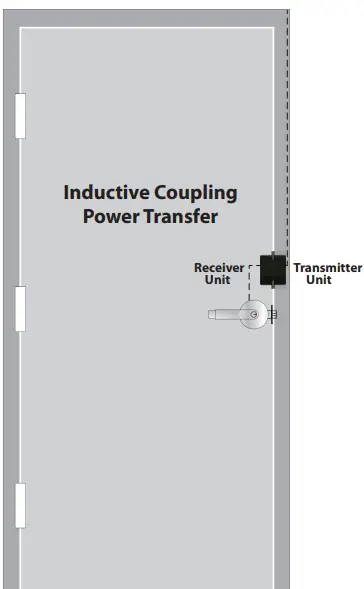
GIANNI WLP-100 Wireless Power Transfer
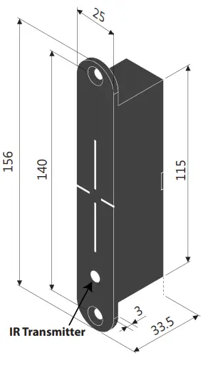
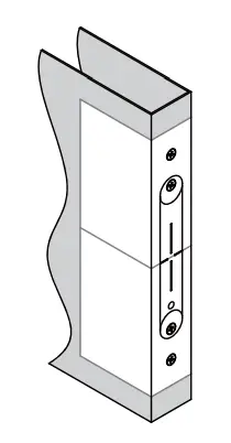
Dimension
Specifications
| Transmitter on Frame Side | |
| Input Power | 27.6 VDC |
| Current Draw | 1A/27.6VDC *Requires 1.5 A power when energized |
| Lock Status Output | Relay (Dry contacts: N.O./N.C./Com.) Rating: 1A/ 30VDC |
| Door Status Output | Reed Switch (Dry contacts: N.O./N.C./Com.) Rating: 0.1A/ 20VDC |
| Receiver on Door Side | |
| Output Power | 12/24 VDC |
| Current Draw | 800mA/12VDC 400mA/24VDC |
| Lock Status Input | Dry contacts: N.O./Com. |
| Infrared Sensing | Transmitter Receiver |
| Door Opening Time | 15 / 30 seconds *For fail-secure locks only |
| Maximum Door Gap | 3/16” (4~5mm) |
| Maximum Tolerance with 3/16″ (4~5mm) Door Gap | Horizontal alignment : 1/16″ (1mm) Vertical alignment : 1/16″ (1mm) IR Sensing: 1/16” (1mm) |
| Operating Temperature | 32° to +120.2°F ( 0° to +49°C ) |
| Humidity | 0 to 85% Non-condensing |
Installation &Wiring
Included in Package
- Door Side Unit
- Wood Screws
- Frame Side Unit
- Metal Screws
- Door Side Template
- Mounting Tabs
- Frame Side Template
- Washers
Note: For optimal performance, it is recommended to minimize the door gap and use the supplied templates. The WLP-100 allows for some horizontal and vertical misalignment. Tolerance for minor misalignment will increase as the door gap decreases.
Installation Steps
- Door & Frame Inspection
After checking the door and frame conditions, apply the templates at the appropriate location. The WLP-100 can be installed on the latch side, hinge side, or top of the door.
1a. Apply the door-side template.
1b. Apply the frame side template. Make sure to align the horizontal and vertical centerlines. - Metal Door Installation
2a. Center punch the screw locations for mounting tabs and counter-sink for the M5 screw. 2b. Cut out the main body on the door.
 2c. Check if the WLP-100 fits well in the cutout and use the file if necessary.
 2d. Install mounting tabs using M5 screws.
- Wood Door Installation
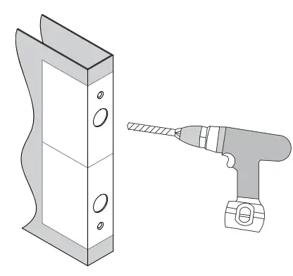
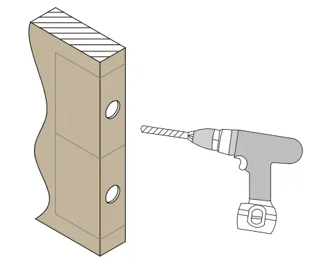
3a. Drill two 1″ (25mm) diameter holes, 1/8″ (3mm) in depth as shown on the template. 3b. Drill and cut the WLP-100 main body to a minimum depth of 1-9/16” (40mm), and a diameter of 1″ (25mm) on the door side.
 3c. Use the chisel to straighten the sides.
 3d. Check if the WLP-100 fits well in the cutout and use the file if necessary.
 3e. For the door side unit, drill a wiring channel to the electrified device to be powered.
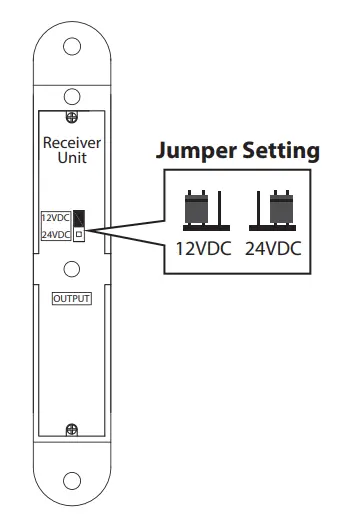
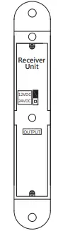
- Selecting the Lock Output Voltage
Use the jumper on the back of the door-side unit to select the appropriate lock voltage.
- Frame Installation
 2b. Cut out the main body on the door.
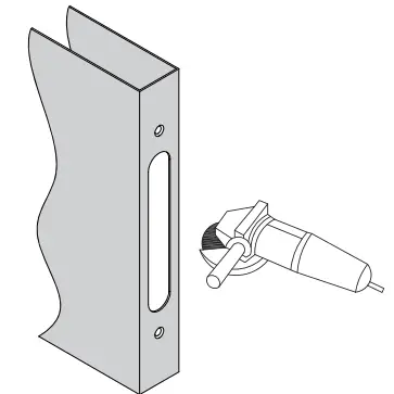 2c. Check if the WLP-100 fits well in the cutout and use the file if necessary.
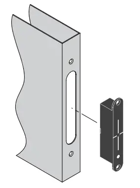 2d. Install mounting tabs using M5 screws.
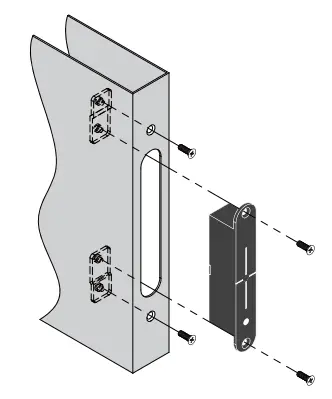
 3b. Drill and cut the WLP-100 main body to a minimum depth of 1-9/16” (40mm), and a diameter of 1″ (25mm) on the door side.
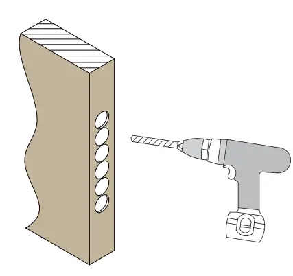 3c. Use the chisel to straighten the sides.
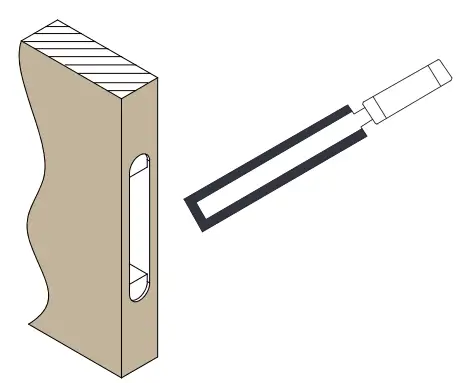 3d. Check if the WLP-100 fits well in the cutout and use the file if necessary.
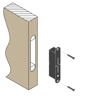 3e. For the door side unit, drill a wiring channel to the electrified device to be powered.
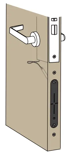
For the frame side unit, repeat steps 2 or 3 to install on a metal or wood frame.
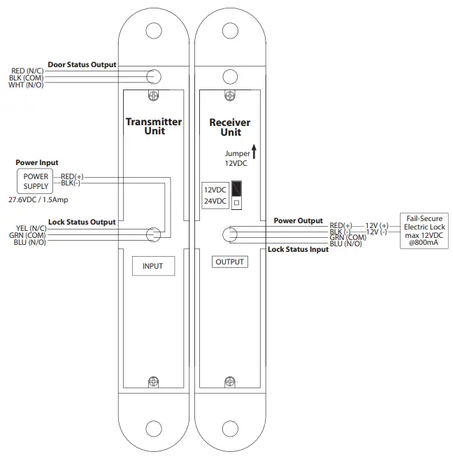
Wiring Instructions
Please refer to the wiring diagrams on page 5, 6.
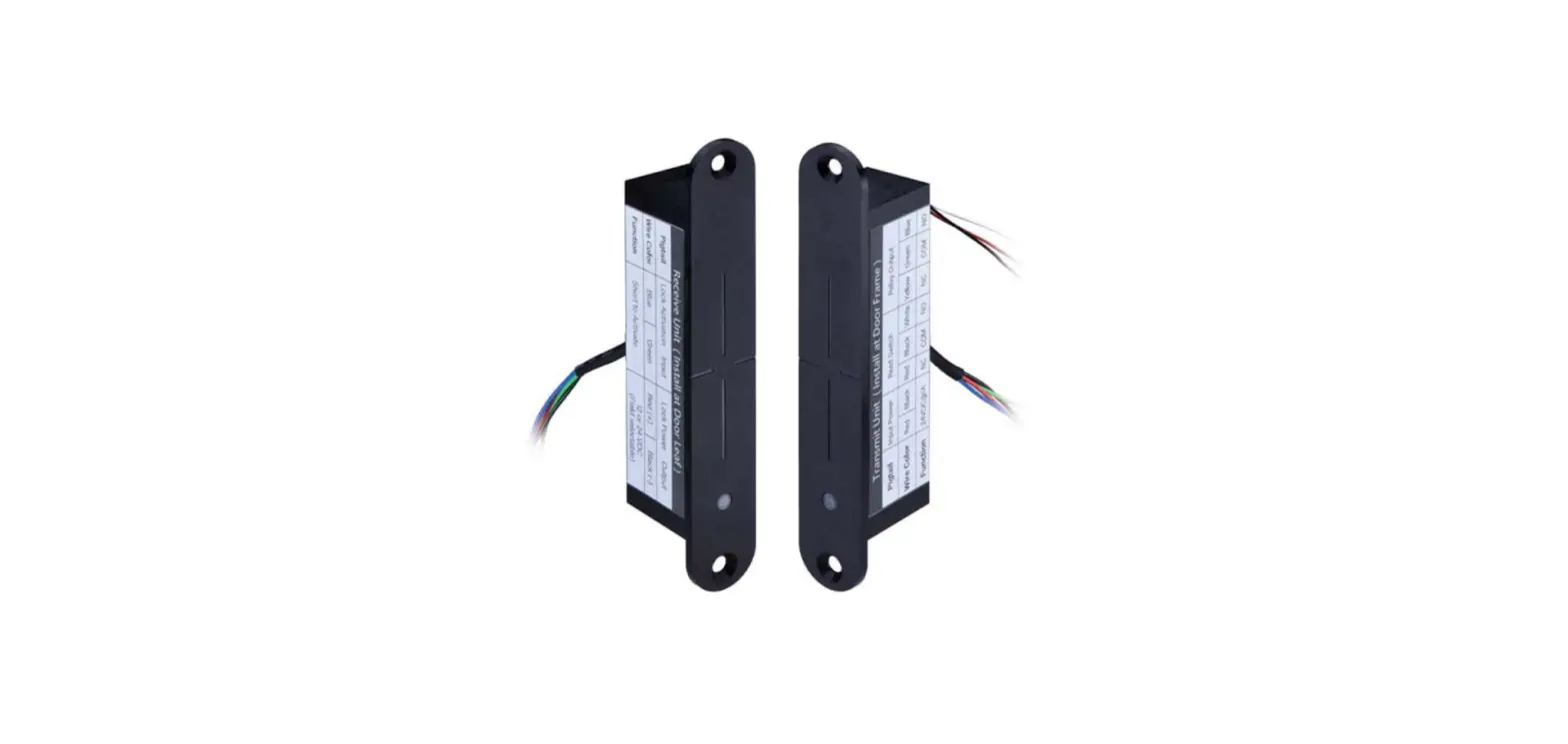
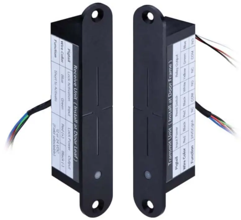
| WLP-100 | Pigtail | Wire Color | Function | |
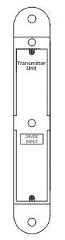 | The frame (Transmitter) | Input Power | Red (+) | 27.6VDC / 1.5Amp |
| Black (-) | Ground | |||
| Reed Switch | Red | N.C. | ||
| Black | COM. | |||
| White | N.O. | |||
| Relay Output (Lock Status) | Yellow | N.C. | ||
| Green | COM. | |||
| Blue | N.O. | |||
| Receiver Unit
12VDC 24VDC OUTPUT | Door Leaf (Receiver) | Lock Status Input | Blue | N.O. |
| Green | COM. | |||
| Lock Power Output | Red (+) | 12 or 24VDC (select through jumper setting) | ||
| Black (-) | ||||
WLP-100 Wiring Diagram (1)
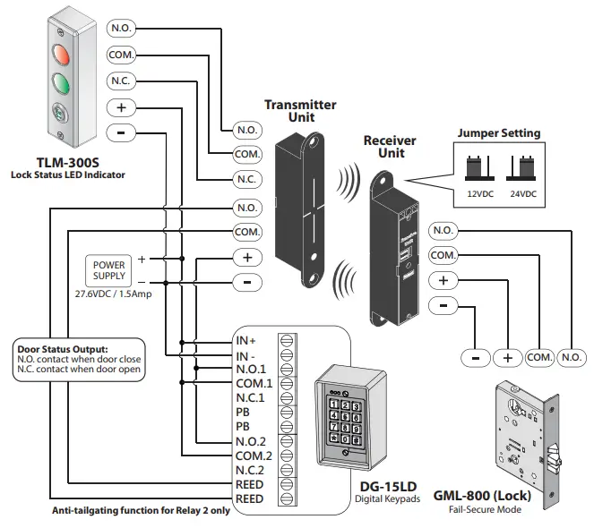
WLP-100 Wiring Diagram (2)

- Copyright © All Rights Reserved. P-MU-WLP-100 Published: 2022.05.13


