![]()
WPT Series Wireless Power Transfer
Instruction Manual
INSTALLATION INSTRUCTIONS
WPT
Wireless Power Transfer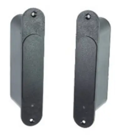
Technical Specifications:
Note – For Use with Fail-Secure (Power to Unlock) Locks Only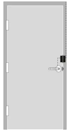
| Input Power (Frame Side): | 600mA @ 24VDC |
| Output Power (Door Side): | 600mA/300mA @ 12/24VDC (Field Selectable} |
| Maximum Door Gap: | 1/4″ (-7mm) |
| Maximum Tolerance with 3/16″ (5mm) Gap: | Horizontal < 5/64″ (2mm) Vertical < 5/64″ (2mm) |
| Dry Inputs (Frame Side): | (2) Door Unlock Trigger (Timed) 1.4 Second Fixed 2.1-90 Seconds Manual |
| Dry Inputs (Door Side) | (2) Relay Activation for REX, Latch Status, etc. |
| Dry Outputs (Frame Side): | (2) SPDT Relay, IA @ 30VDC (2) Solid State Relay, N/O 100mA @ 60VDC |
| LED Indicators: | Frame & Door Side |
| Operating Temperature: it | -4°F – 140°F(-20°C – 60°C) |
| Compliance: | UL1034; UL1OC for 3 Hours, FCC Part 15 |
Any suggestions or comments to this instruction or product are welcome. Please contact us through our website or email [email protected]
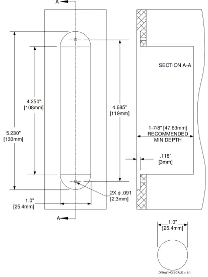
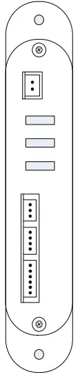
WPT Dimensions
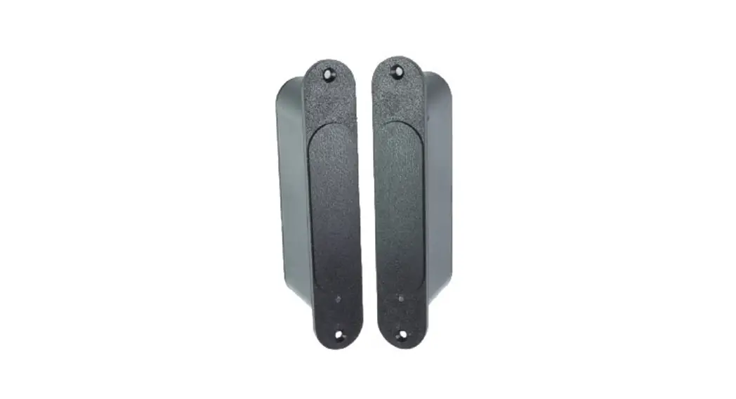
FRAME SIDE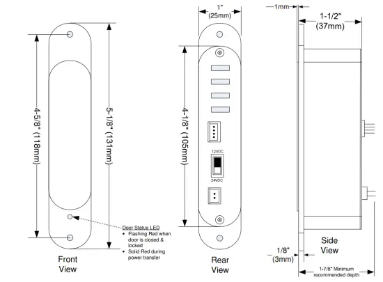
DOOR SIDE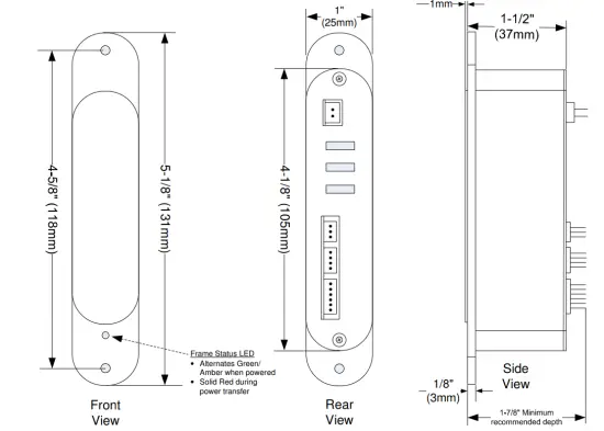
WPT Installation & Wiring
Package Contents:
| • Door Side Unit • Frame Side Unit • Door Template • Frame Template | • 4″ Wire Harnesses > (2) 2-wire > (1) 3-wire > (2) 4-wire > (1) 6-wire | • Wood Screws • Metal Screws • Mounting Tabs |
Note: Optimal performance of the WPT will depend on minimizing the door gap, and using the supplied templates. Although the WPT allows for some horizontal and vertical misalignment, these tolerances will decrease as the door gap increases.
1. Inspect the door & frame, and apply the templates at the desired location. The WPT may be installed on the latch side, hinge side, or top of the door.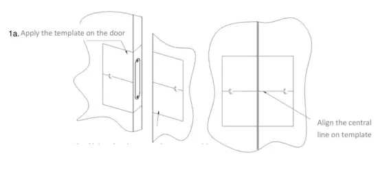
1b. Using the door template as a guide, apply the template on the frame, aligning the horizontal & vertical centerlines.
2. For metal door installations:
2a. Center punch the tab-mounting screw locations and counter-sink for an M3 screw.
2b. Saw or rout out the entire main pocket.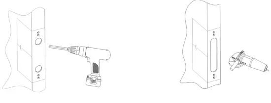
2c. Verify that the WPT face fits in the cutout, and file as necessary.
2d. Install mounting tabs using M3 screws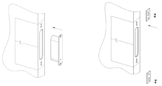 3. For wood door installations, use the recommended wood door jig, or follow the steps below:
3a. Drill (2) 1″ (25mm) diameter holes, 1/8″ (3mm) in depth as shown on the template
3b. Drill out the main WPT pocket to a minimum depth of 1-7/8″ (48mm), and diameter of 1″ (25mm)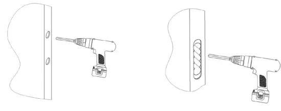 3c. Carefully use a chisel to straighten the sides.
3d. Verify that the WPT unit fits in the cutout, and file as necessary.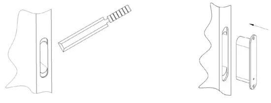 3e. For the door side unit, drill a wiring channel to the electrified device to be powered.
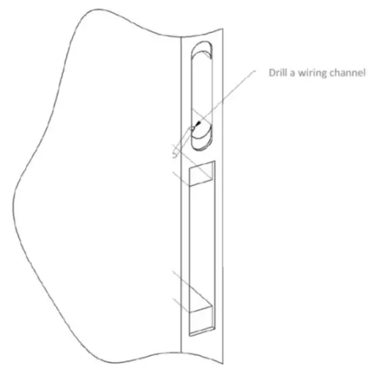
4. Select the Lock Output Voltage. Use the slide switch on the back of the door side unit to select the appropriate lock voltage.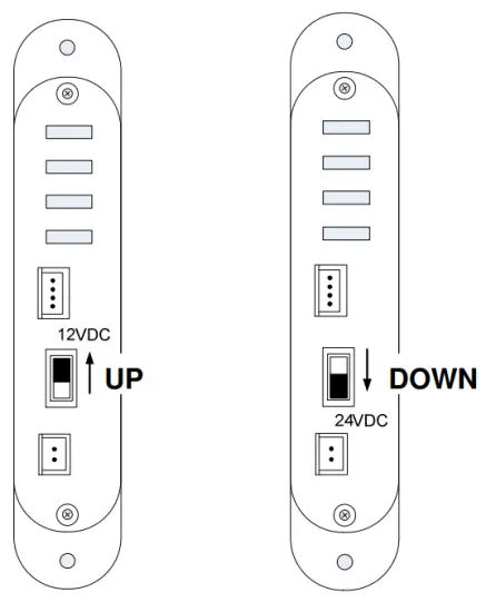 5. Repeat steps 2 or 3 for the installation of the frame side unit in a metal or wood frame.
6. Terminate wiring to both of the WPT units.
6a. Wiring Overview. Items marked as “Required” are the minimum connections required to control an electrified lockset. Select Momentary Activation, or Maintained, or both. Use the wiring diagrams on Page 7 as a reference.
| WPT Unit | Pigtail | Wire Color | Function | ‘Required X | |
 | FRAME | Input Power (Continuous) | RED | 24VDC (+) @ 600mA | |
| BLACK | Ground | ||||
| Activation Triggers | GREEN | Momentary Activation (fixed 4 seconds) | X | ||
| YELLOW | Activation Common | ||||
| BROWN | Maintained Activation (up to 90 secs.) | ||||
| Solid State Outputs | BLUE | Door Status (Closed when the door closed) | |||
| GRAY | |||||
| YELLOW | Error Status (Closed when tampered) | ||||
| WHITE | |||||
| Relay Outputs | BLACK/WHITE | Normally Closed #1 | |||
| GRAY/WHITE | Common #1 | ||||
| PURPLE/WHITE | Normally Open #1 | ||||
| GREEN/WHITE | Normally Closed #2 | ||||
| BLACK/YELLOW | Common #2 | ||||
| PINK | Normally Open #2 | ||||
| W PT Unit | Pigtail | Wire Color | Function | Required | |
 | DOOR | Relay Activation Inputs | BLUE | Relay #1 Activation {Short to Activate} | |
| GRAY | |||||
| YELLOW | Relay #2 Activation {Short to Activate} | ||||
| WHITE | |||||
| Lock Power Output | ORANGE | 12 or 24 VDC (+) (Field selectable} | X | ||
| BLACK | 12 or 24 VDC (-) (Field selectable} | ||||
6b. Wiring Examples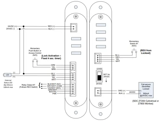
7. Mount both WPT units using the appropriate screws. Apply continuous power to the frame side. If using a momentary switch to activate the lock, hold for a second or two, then release. Power will be provided to the lock for approximately 4 seconds.
TEMP-WPT METAL DOOR/FRAME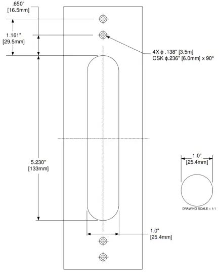
TEMP-WPT WOOD DOOR/FRAME