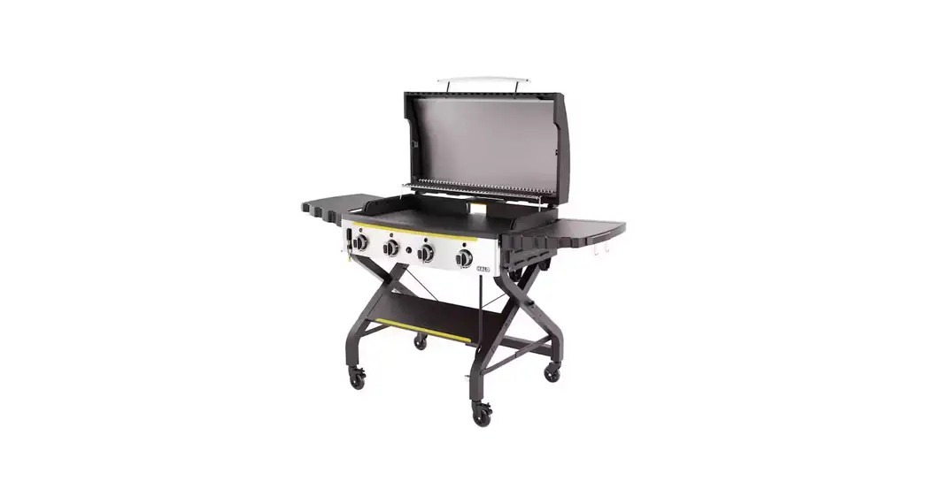
![]() HZ-1001-XNA Elite4B 8 Zone Outdoor Black Griddle
HZ-1001-XNA Elite4B 8 Zone Outdoor Black Griddle
User Guide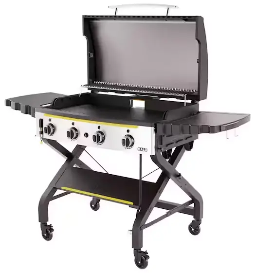
HZ-1001-XNA Elite4B 8 Zone Outdoor Black Griddle
![]() WARNING
WARNING
The manufacturer has made every effort to eliminate any sharp edges. However, you should handle all components with care to avoid accidental injury.
NOTICE: Before assembly, make sure all parts are present. If any part is missing or damaged, do not attempt to assemble the appliance. Contact customer service for replacement parts at 1-833-572-1688.
NEED MORE INSTRUCTIONS?
Scan for registration, assembly videos, care + use, warranty, recipes, + more.

BATTERY NOT INCLUDED. Requires 1 AA battery for igniter.
IMPORTANT: Please read all instructions thoroughly before proceeding. Find a large, clean area in which to assemble your HALO Elite 4B Outdoor Griddle. Please refer to the assembly diagram, as necessary.
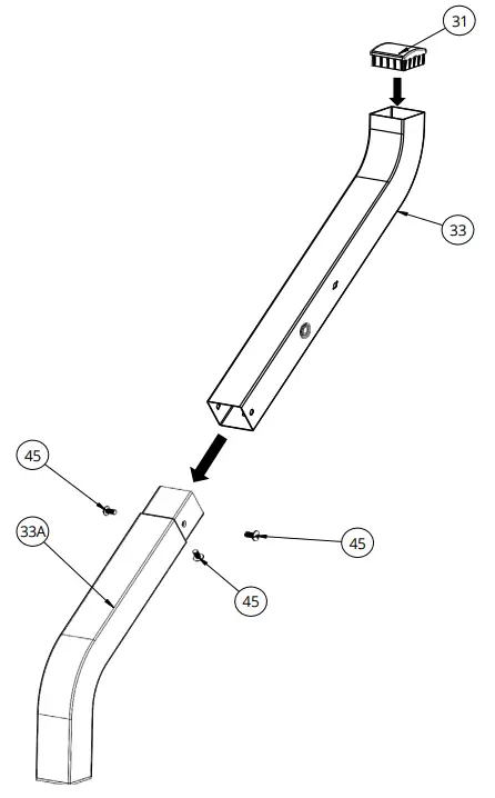
- Install left inner leg using 3-M6 x 14 mm screws. Install leg cap.
NOTICE: Make sure all the plastic protection is removed before assembling. Tool required for assembly: #2 Phillips Screwdriver
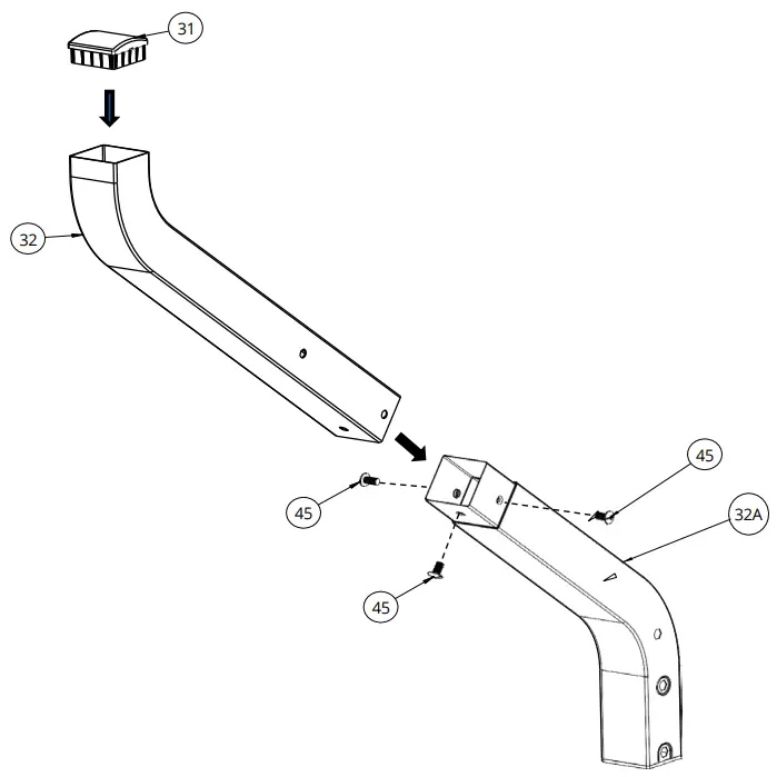
ITEM PART DESCRIPTION QTY PART # 31 Cap-Leg 1 HZ-1001-48 33 Left-Inner Leg-Long 1 HZ-1001-25 33A Left-Inner Leg-Short 1 HO-1001-26 45 M6 x 14 mm Screw 3 HZ-1001-40 - Install left outer leg using 3-M6 x 14 mm screws. Install leg cap.

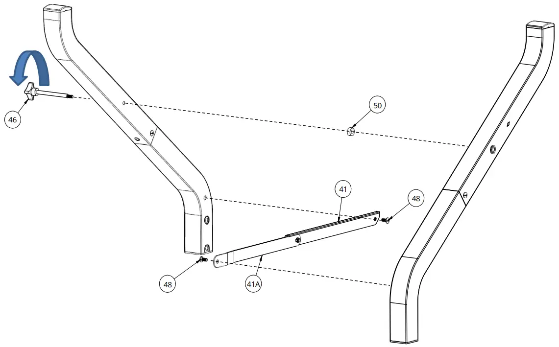
ITEM PART DESCRIPTION QTY PART # 31 Cap-Leg 1 HZ-1001-48 32 Left-Outer Leg-Long 1 HZ-1001-23 32A Left-Outer Leg-Short 1 HZ-1001-24 45 M6 x 14 mm Screw 3 HZ-1001-40 - Install left outer leg assembly and left inner Leg assembly using pivot bracket 41 and 41A, 2-M6 x 3H Shoulder screws, M6 x 93 mm knob with threaded shaft and nylon spacer. Tighten screws firmly. Set assembly aside.
ITEM PART DESCRIPTION QTY. PART # 41 Pivot Bracket-A 1 HZ-1001-36 41A Pivot Bracket-B 1 HZ-1001-37 46 M6 x 93 mm Knob with Threaded Shaft 1 HZ-1001-41 48 M6 x 3H Shoulder Screw 2 HZ-1001-43 50 Nylon Spacer 1 HZ-1001-45 
 WARNING
Pinch Points
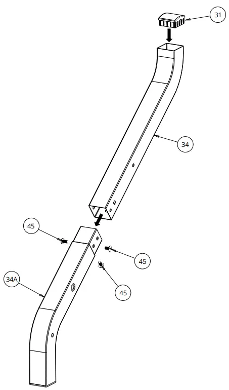
- Install right inner leg assembly using 3-M6 x 14 mm screws. Install leg cap.
ITEM PART DESCRIPTION QTY. PART # 31 Cap-Leg 1 HZ-1001-48 34 Right-Inner Leg-Long 1 HZ-1001-27 34A Right-Inner Leg-Short 1 HZ-1001-28 45 M6 x 14 mm Screw 3 HZ-1001-40 
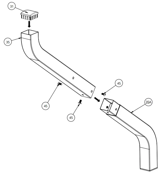
- Install right outer leg assembly using 3-M6 x 14 mm screws. Install leg cap.
ITEM PART DESCRIPTION QTY. PART # 31 Cap-Leg 1 HZ-1001-48 35 Right-Outer Leg-Long 1 HZ-1001-29 35A Right-Outer Leg-Short 1 HZ-1001-30 45 M6 x 14 mm Screw 3 HZ-1001-40 
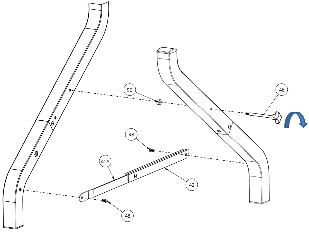
- Install right outer leg assembly and right inner leg assembly using pivot bracket 42 and 41A, 2-M6 x 3H shoulder screws, M6 x 93 mm knob with threaded shaft and nylon spacer. Tighten screws firmly. Set assembly aside.
ITEM PART DESCRIPTION QTY. PART # 41A Pivot Bracket-B 1 HZ-1001-37 42 Pivot Bracket-C 1 HZ-1001-38 46 M6 x 93 mm Knob with Threaded Shaft 1 HZ-1001-41 48 M6 x 3H Shoulder Screw 2 HZ-1001-43 50 Nylon Spacer 1 HZ-1001-45  WARNING
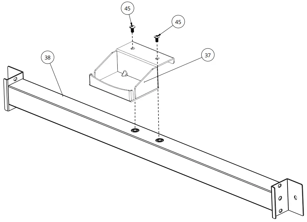
Pinch Points - Install tank retention support bracket and rear brace using 2-M6 x 14 mm screws.
ITEM PART DESCRIPTION QTY. PART # 37 Tank Support Bracket 1 HZ-1001-32 38 Rear Brace 1 HZ-1001-33 45 M6 x 14 mm Screw 2 HZ-1001-40 
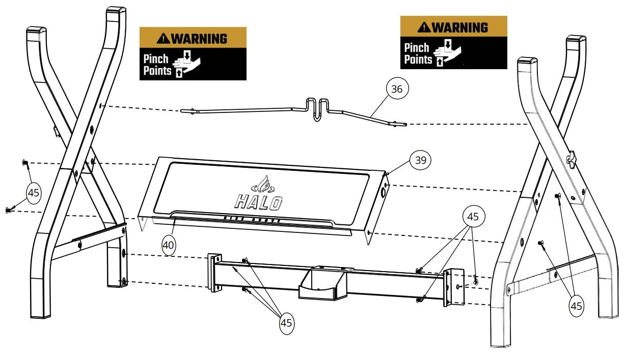
- Install tank retention, front panel and rear brace assembly using 10-M6 x 14 mm screws. Tighten screws firmly.
IMPORTANT: Do not tighten screws completely until all screws for this step have been installed.ITEM PART DESCRIPTION QTY. PART # 36 Tank Retention Wire 1 HZ-1001-31 39 Front Panel 1 HZ-1001-34 40 RISE ABOVE Logo Plate 1 HZ-1001-35 45 M6 x 14 mm Screw 10 HZ-1001-40 
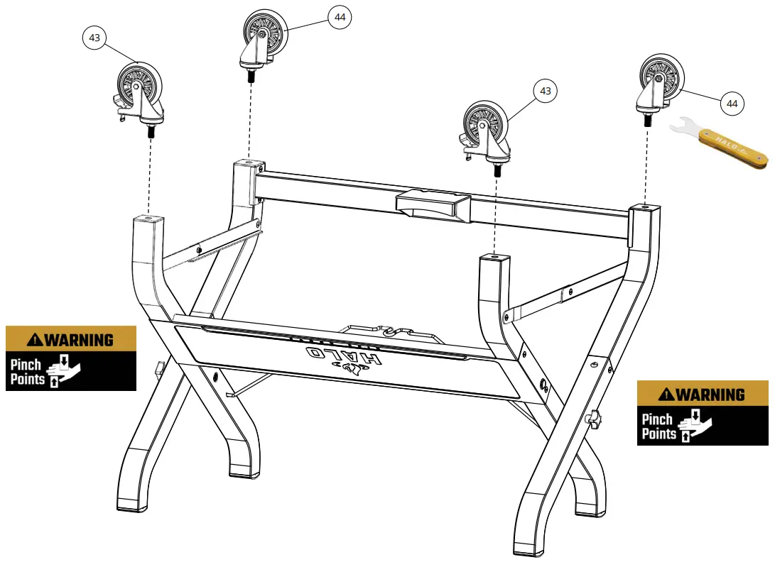
- Attach the casters using M12 caster wrench. Mount locking casters to front legs and mount swivel casters to rear legs.
NOTE: You can lock the casters that have locks, allowing you to assemble the caster without using a caster wrench.ITEM PART DESCRIPTION QTY. PART # 43 Caster with Lock 2 HZ-1006-XNA-13 44 Caster-Swivel 2 HZ-1006-XNA-12 
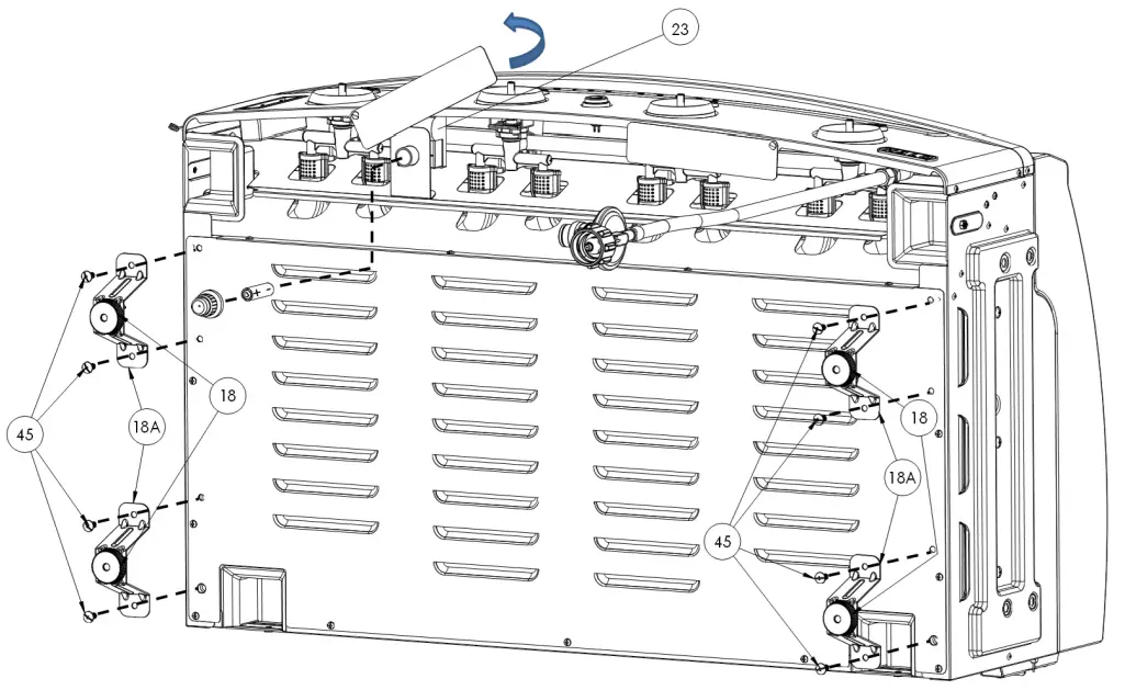
- Turn the fire chamber and lid assembly on its back, then rotate the lighting instruction tag outward. Turn the battery cap counterclockwise to insert (1) AA battery. Attach 4-foot brackets using 8-M6 x 14 mm screws.
ITEM PART DESCRIPTION QTY PART # 18 Adjustable Foot 4 HZ-1004-16 18A Foot Bracket 4 HZ-1004-16A 23 Electronic Igniter Module w/ 4 Outlets 1 HZ-1001-19 45 M6 x 14 mm Screw 8 HZ-1001-40 
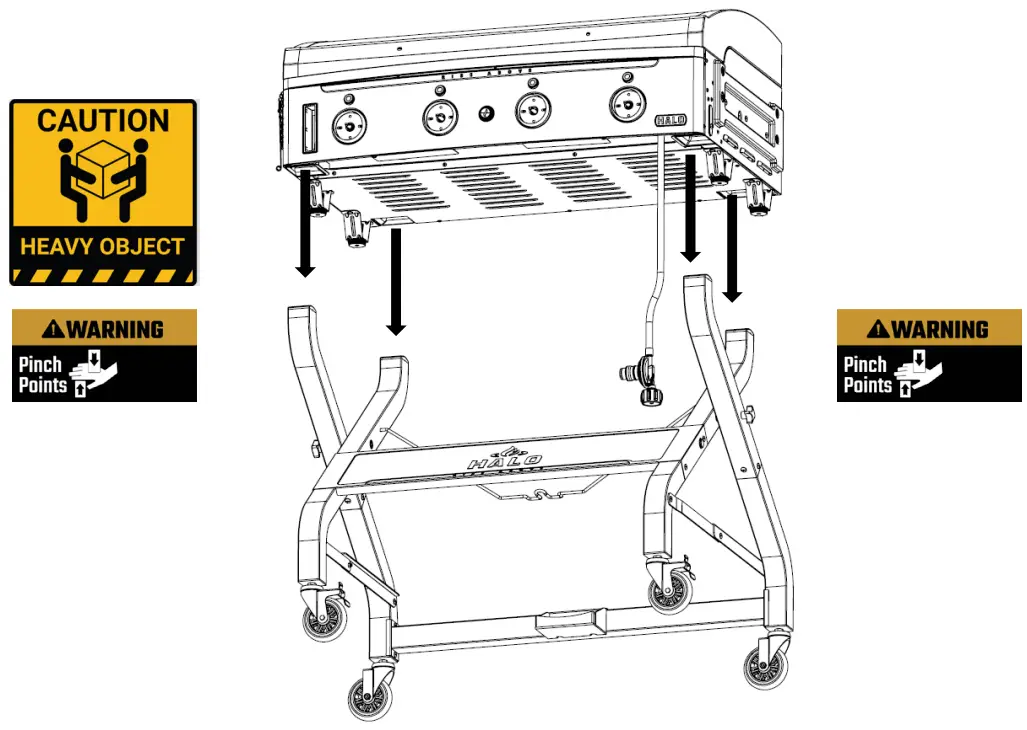
- Turn the cart right side up. Attach fire chamber assembly to the “X” frame using 4-1/4″-20 x 15 mm knob with threaded shaft.
NOTE: We recommend the help of a friend to attach the upper section of the cooking chamber to the “X” cart frame due to the size and weight of the fire chamber assembly.ITEM PART DESCRIPTION QTY. PART # 47 1/4″-20 x 15mm Knob with Threaded Shaft 4 HZ-1001-42A  NOTE: We recommend the help of a friend to attach the upper section of the cooking chamber to the “X” cart frame due to the size and weight of the fire chamber assembly.
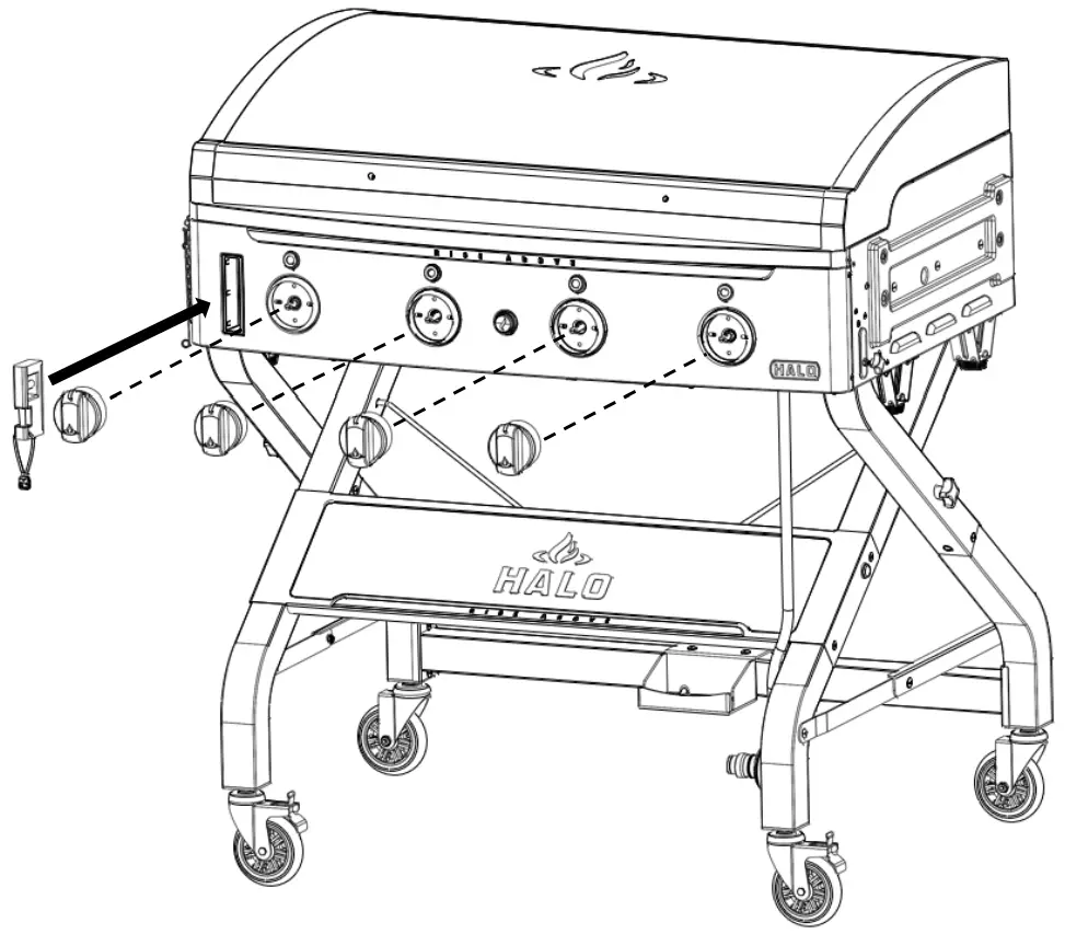
- Install control knobs and insert leveler into housing.
ITEM PART DESCRIPTION QTY. PART # 20 Control Knob-Common 4 HZ-1004-38 26 Leveler 1 HZ-1007-21 
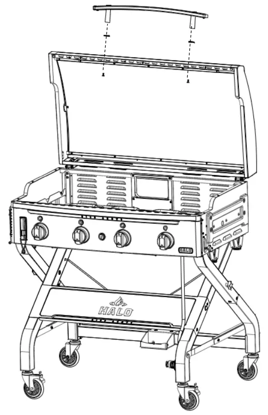
- Attach lid handle assembly using 2-M6 x 14 mm screws.
ITEM PART DESCRIPTION QTY PART # 2 Lid Handle Assembly 1 HZ-1001-02 3 Lid Handle Standoff-Bezel 2 HZ-1001-03 45 M6 x 14 mm Screw 2 HZ-1001-40 
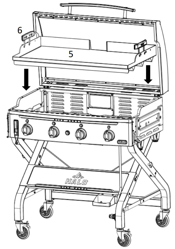
- Install griddle plate onto the fire chamber using 2-“JJ” hook handles.
ITEM PART DESCRIPTION QTY. PART # 5 Griddle Plate 1 HZ-1001-05 6 JJ Hook Handle-L & R 2 HZ-1001-06 
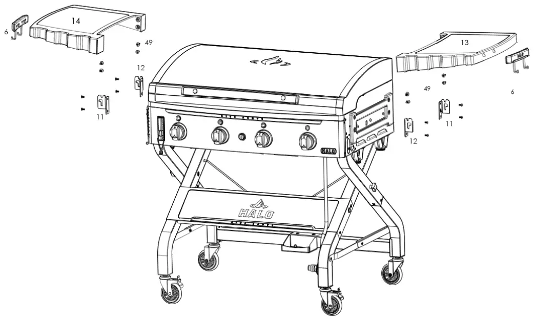
- Install left and right side table brackets using 8-M6 x 14 mm screws. Install left and right side tables using 8-M6 x 7H shoulder screws.
ITEM PART DESCRIPTION QTY. PART # 6 JJ Hook Handle-L & R 2 HZ-1001-06 11 Bracket-Side Table-A 2 HZ-1001-10 12 Bracket-Side Table-B 2 HZ-1001-11 13 Side Table-Right 1 HZ-1001-12 14 Side Table-Left 1 HZ-1001-13 45 M6 x 14 mm Screw 8 HZ-1001-40 49 M6 x 7H Shoulder Screw 8 HZ-1001-44 
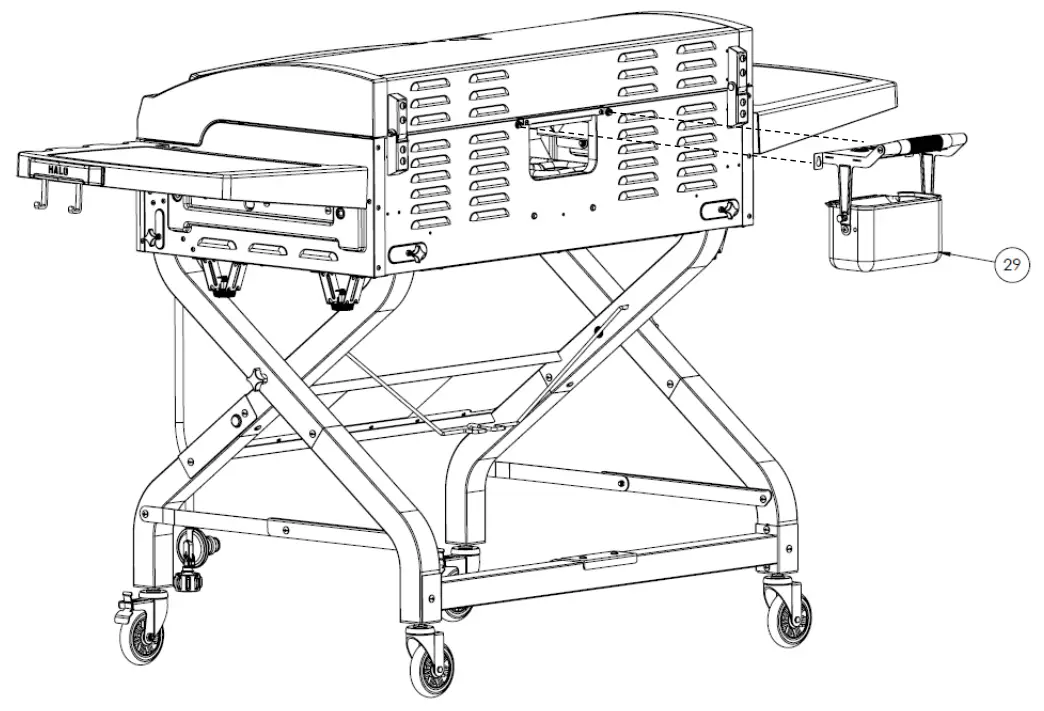
- Install grease cup and cover.
ITEM PART DESCRIPTION QTY. PART # 29 Grease Cup with Cover 1 HZ-1001-22 
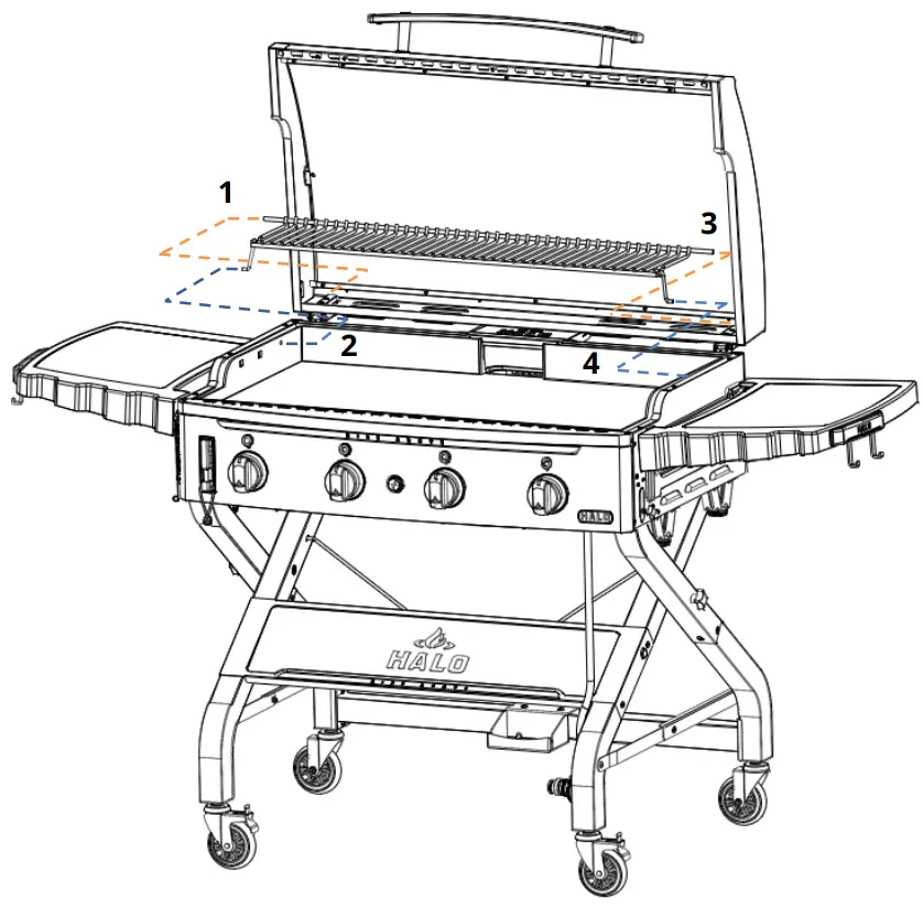
- Install swing away warming rack following steps 1-4.
ITEM PART DESCRIPTION QTY. PART # 52 Warming Rack 1 HZ-1001-47 
 NOTE: We recommend the help of a friend to attach the upper section of the cooking chamber to the “X” cart frame due to the size and weight of the fire chamber assembly.
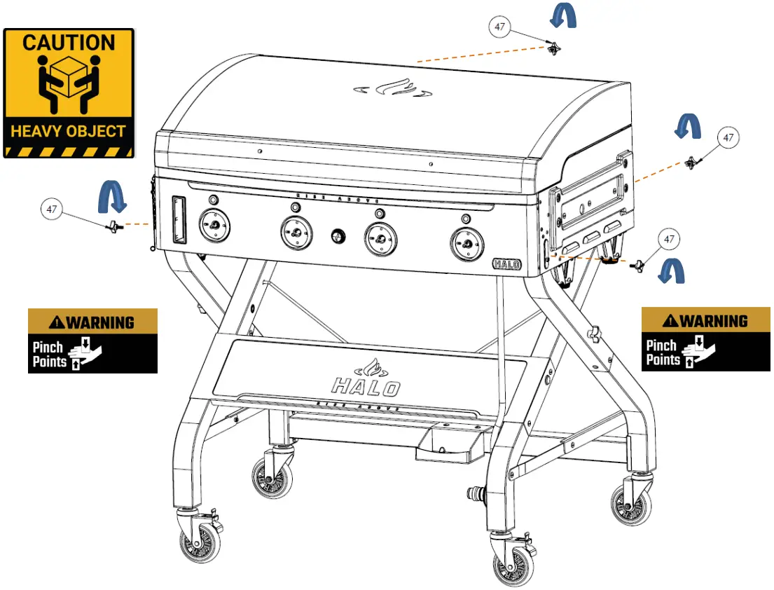
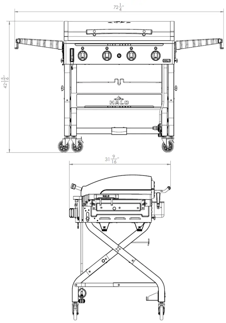
ASSEMBLED DIMENSIONS
Quick link ![]()
REGISTER YOUR ELITE 48 PRODUCT ASSEMBLY VIDEOS RECIPES + more