![]()
HU02 Smart Lock
Installation Guide
Installations Guide
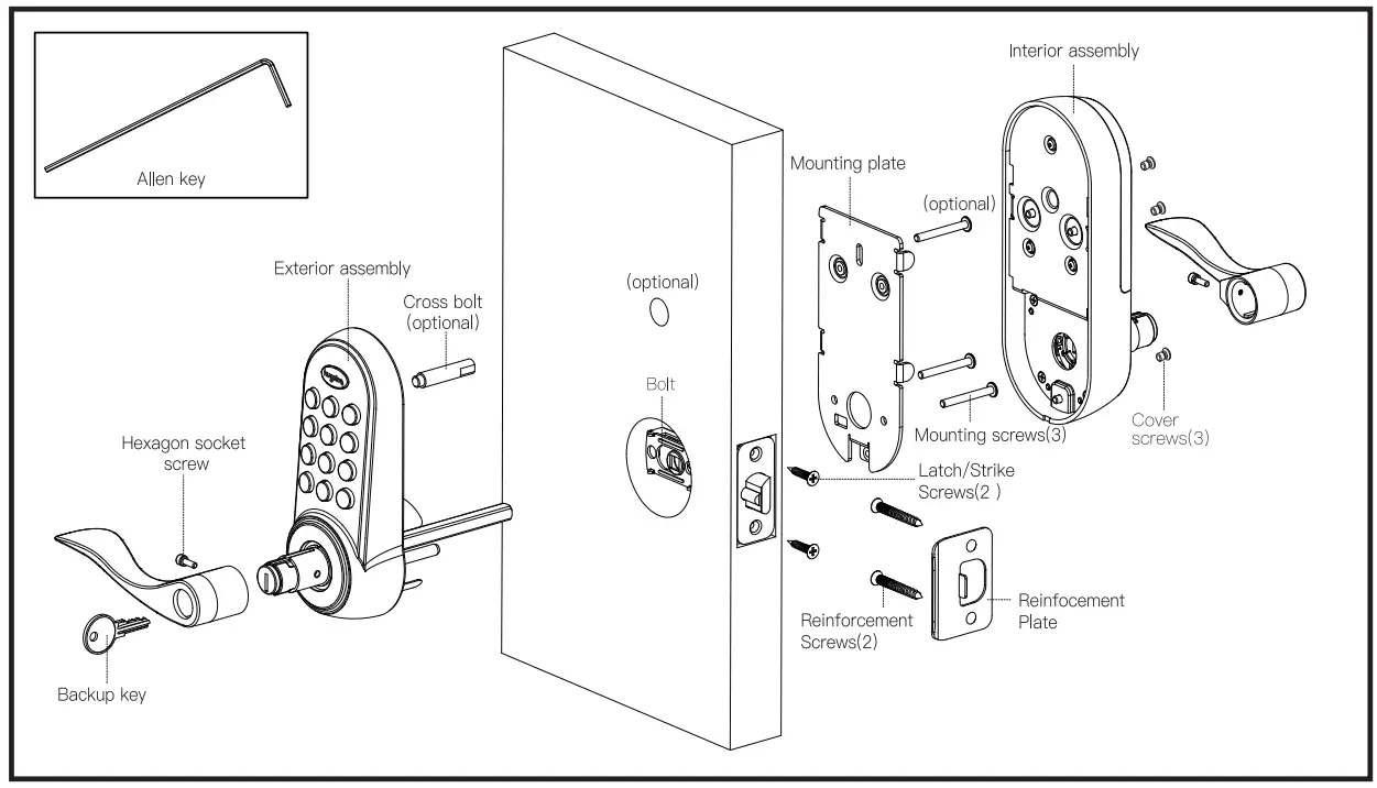
Additional Parts
Optional Bolt Faceplate Tool Needed
Door prep
- 2-1/8″ (54mm) hole saw
- 1″ (26mm) boring bit
- 7/64″ (2.5mm) drill bit
- 3/8″ (10mm) drill bit
- Chisel&Hammer
Lock Installation #2 Philips screwdrive
Important Notice:
Make sure your door is prepared prior to installation. Only drill an upper hole if you wish the lock to have added stability. Please refer to the provided template for drilling if needed.
Exterior assembly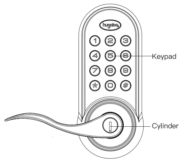 Interior assembly
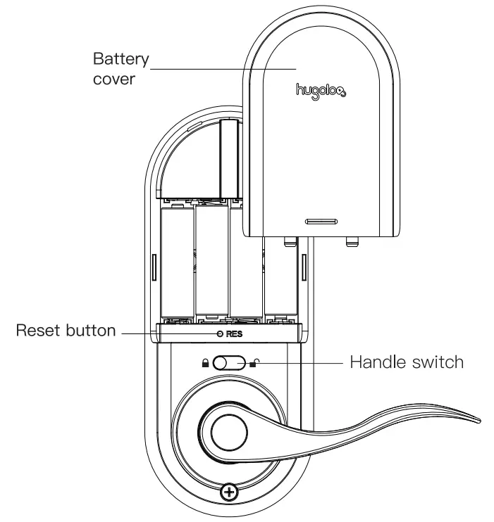
Hugolog INC. reserves all rights for the final Interpretation of this Instruction![]() All design and specifications are subject to change without notice
All design and specifications are subject to change without notice
Preparing for Installation
A. Measure the dimension of the hole shown.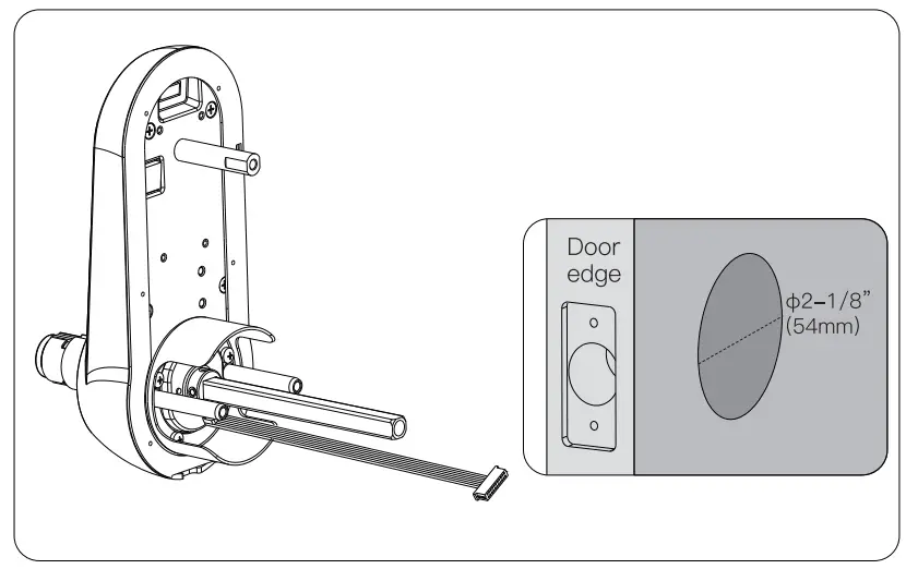 B. Change the faceplate, if necessary.
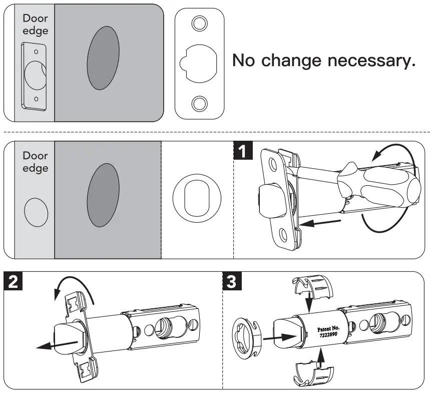 C. Adjust the Iatchbolt.
NOTE: Belt ships with a basket in 2-3/8113Orrtn) position. If required tum the bolt case and pill to extend to a 2-3/C (70 mm)backset position. (see pictures below)![]() The bolt must be in a retracted(unlocked) position when you are changing the backset.
The bolt must be in a retracted(unlocked) position when you are changing the backset.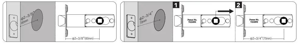
Installation
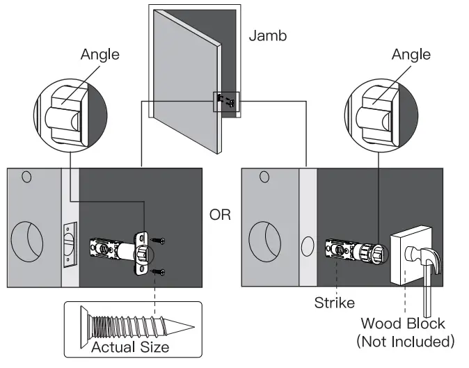
- Install latch.
 NOTE: Make sure latch angle faces door jamb.
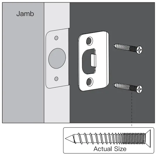
- Install strike onto the door jamb.

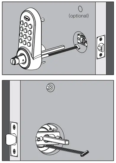
- Install keypad
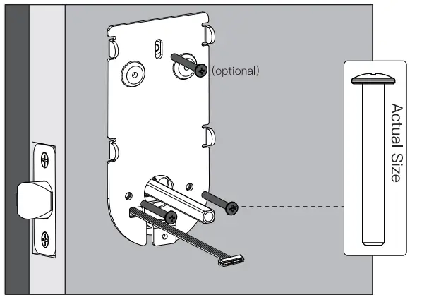
This hole is for the optional cross-bolt provided for stabilizing your lock. If you drilled a hole, securely tighten the post before mounting it on your door.
The bar should slide smoothly through a hole in the latch. If not, check door dimensions.
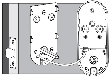
NOTE: Cable must go through the door hole under the latch.
- Positon the inside mounting plate by first routing the cable and connector through the mounting plate’s cable hole. Secure both assemblies using 8/30 screws.

- Attach cable assembly to the interior assembly PCB by lining up notches on top of cable connector to slots on PCB connector. Press connector firmly using thumbs until completely connected.

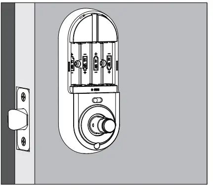
- Install interior assembly on inside mounting plate.

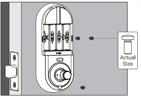
- Secure using a screw through the Interior assembly onto the mounting plate.

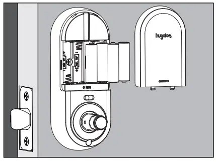
- Install I battery and battery cover

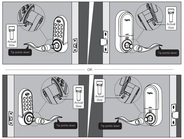
- Press levers onto lever posts and tightens the screws by alien key.

![]()


