Super Handy 330lbs Material Lift User Manual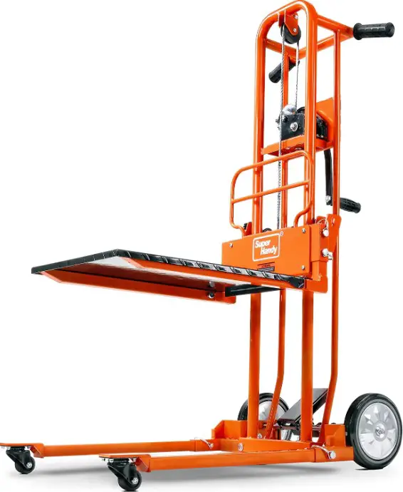
![]() WARNING:
WARNING:
Carefully review and understand all INSTRUCTIONS prior to operating this device. Failure to follow the safety rules and other basic safety precautions may result in serious personal injury. Keep these instructions in a safe place and accessible so that they can be reviewed as required. Keep these instructions to assist in future servicing needs.
WARNING
- Before using or performing maintenance on your Material Lift, please read the manual thoroughly to familiarize yourself with the proper usage of and maintenance of your product.
- This Material Lift should only be used in a professional and safe manner, Maintenance and Testing Personnel should only use this equipment when necessary.
- The material lift must be inspected before use, if a material lift is damaged, has malfunctioning or missing parts, do not use, contact the manufacturer for replacememt parts.
- Unauthorized modifications to the product in any way are not permitted and can be dangerous. Unauthorized modifications will automatically void all product warranty and the manufacturer bears no liability to damages or injuries caused by such unauthorized modifications..
- Do not place your legs, feet or other body parts under the lift during using.
- This lift is not designed for the use of transporting or lifting people, pets or livestock of any sort.
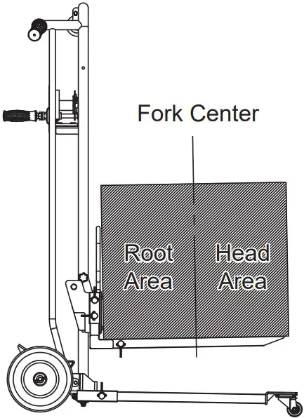
- To avoid the risk of lift overturning when loading, ensure that the center of gravity of the heavy objects is in the right place on the forks or flatbed (refer to 7.1).
- All heavy objects should be centered properly before lifting or moving the unit.
- Do not turn the winch counterclockwise to lift weight.
- Do not put nylon rope close to a fire source or sharp objects,such as blade.
- Do not overload the lift.
- The operator must not leave the lift unattended while in use during the lifting process of the heavy objects. When walking away from the Lift, operator must lower the height of the heavy objects.
- Do not remove or obscure the labels on the lift, make sure all labels are clear and easy to read, otherwise do not use it.
- Do not operate this material lift if you are under 16 years old.
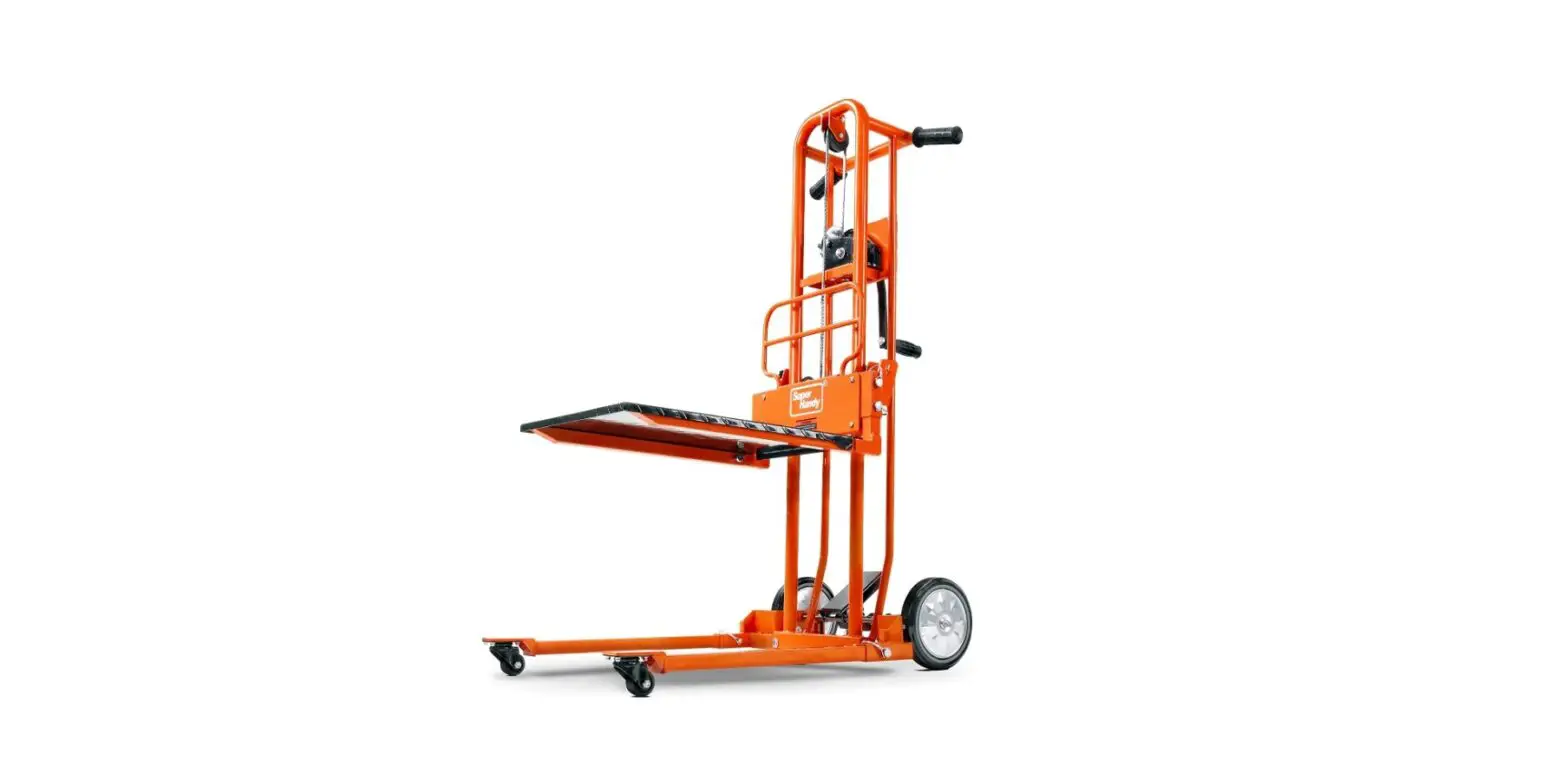
MAIN USE
Material lift with compact design and ease of operation. Intended for small and medium-sized warehouses, processing workshops, home areas handling or loading and unloading heavy objects, can achieve short distance or small space to move heavy objects and other operations.
TECHNICAL SPECIFICATIONS
| SKU# | GUO097 |
| Lifting Height | 39.37″ (1000mm) |
| Max. Lifting Weight | 330lbs (150kg) |
| Towing Form | Fork; Flatbed (option) |
| Size | 38.2 “x23.6 “x51.2” (970x600x1300mm) |
| Net Weight/gross Weight | 79lbs(36kg) / 94lbs(43kg) |
- The maximum load capacity of the heavy objects in area from center to root area is 330lbs (150kg).
- The maximum load capacity of the heavy objects in head area is 156lbs (70kg).
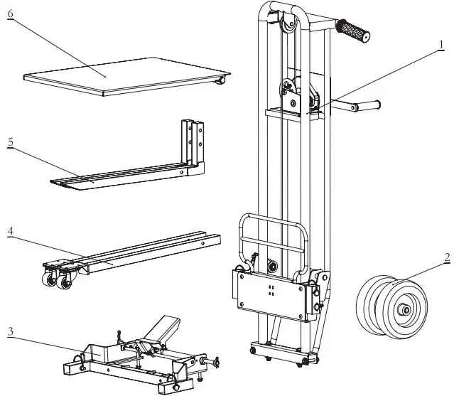
ASSEMBLY
| Part No. | Description | Q’ty | Part No. | Description | Q’ty |
| 1 | Primary frame | 1 | 4 | Wheel carrier | 2 |
| 2 | Universal wheel 8″ | 2 | 5 | Fork | 2 |
| 3 | Base | 1 | 6 | Flat plate | 1 |
- Flat washer 8mm 8 pcs
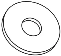
- Flat washer 12mm 8 pcs
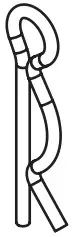
- R-pin 2 pcs
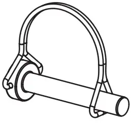
- D-pin 8 pcs
- Hexagon flange bolt M8x60mm 4 pcs
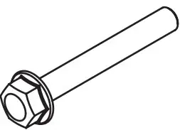
- Nut M8 4 pcs
Assembly Steps
Step 1: Directional Wheel
The directional wheel (B) and flat washer 12mm (C) are inserted into the axle in turn, and then R-pin (A) is inserted into the axle positioning hole.
Follow this procedure for the other side of the directional wheel. (See Fig.1)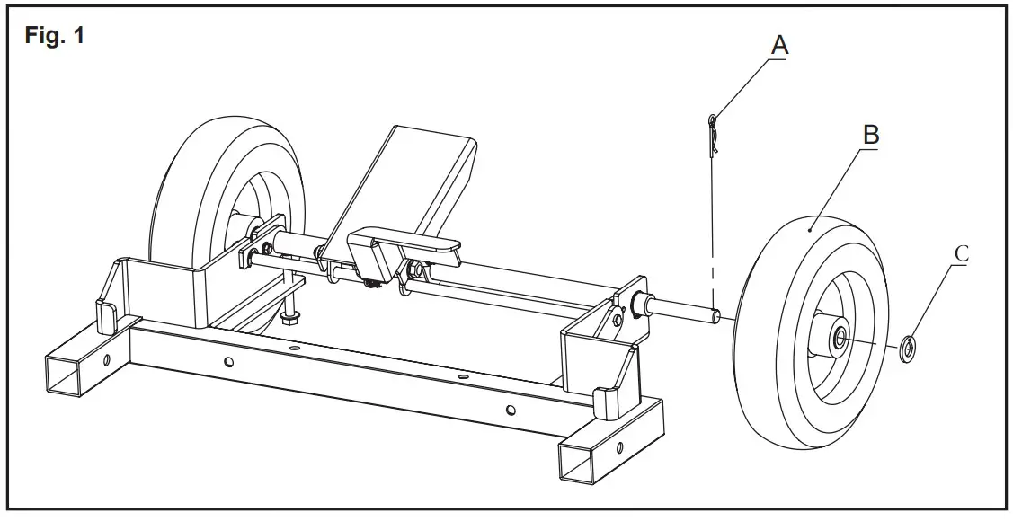
Step 2: Base
Insert the base (B) into the primary frame (A), centering it. Insert M8x60mm bolt (C) through the hole and place 1 spacer (D) on each side, tighten with lock nut (E). Insert the bolt (F) from the left side according to the figure, and install the base. (See Fig.2)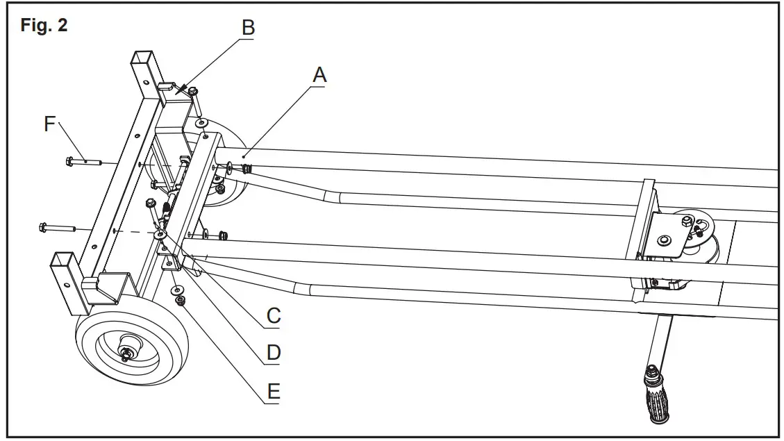
Step 3: Wheel carrier
Insert the wheel carrier (C) into the base (A) interface, then insert the D-pin (B) into the positioning hole and secure it to prevent loosening. If the wheel carrier (C) still slides, the corresponding D-pin (B) is not properly connected and secured. (See Fig.3)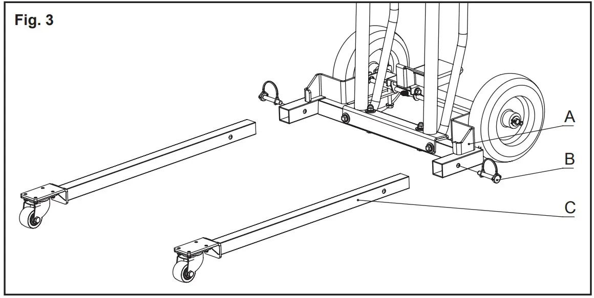
Step 4. Fork
Insert the fork (C) into the fork interface (A), making sure the fork (C) hole is aligned with the fork interface (A) hole. Insert the 2 D-pins (B) into the fork interface (A) holes and secure them. (See Fig.4)
Recommended tools: rubber hammer- knock the fork into the hole.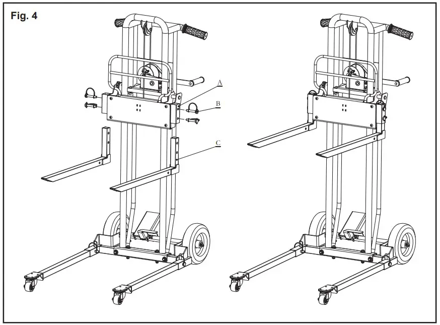
Step 5. Flat plate
The flat plate (B) is placed flat on the fork (C), and the holes on both sides of the plate and the fork are aligned and the D-pin (A) is inserted to fix it. (See Fig.5)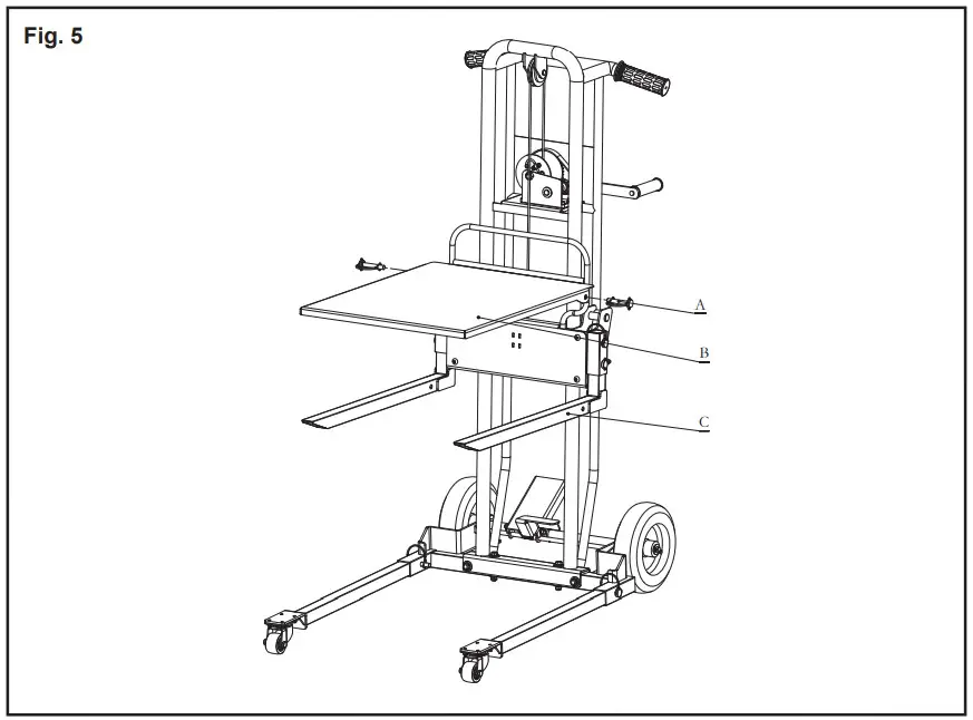
COMMISSIONING&PREPARATION
- Check that all bolts are tightened securely before operation.
- Confirm that the tires are free of cracks, bulges and other defects and that the tire pressure is maintained at 30±2psi.
- Perform a No-load test run prior to initial usage, to confirm that the universal wheel rotation flexible, forward and backward movement freely.
- Verify that the weight being handled or loaded does not exceed 330lb (150kg).
- This equipment with brake device, please park on flat ground. Never leave or park your material Lift with a heavy load on any slope.
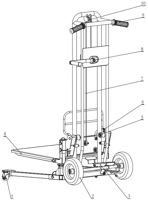
MAIN COMPONENTS
| Part No. | Description |
| 1 | Universal wheel (2″) |
| 2 | Directional wheel (8″) |
| 3 | Brake pedal: control equipment parking |
| 4 | Fork |
| 5 | Roller |
| 6 | Positioning pin |
| 7 | Nylon rope |
| 8 | Winch: handle clockwise rotation to lift the fork height, counterclockwise rotation to lower the fork height. |
| 9 | Handle |
| 10 | Nylon rope rolle |
OPERATION
Placement of heavy objects
a. Place the heavy objects on the fork flatbed with the center of the heavy objects aligned with the center of the fork (shown as below).
b. If the heavy objects may slide, always center the heavy objects and secure it to the forks.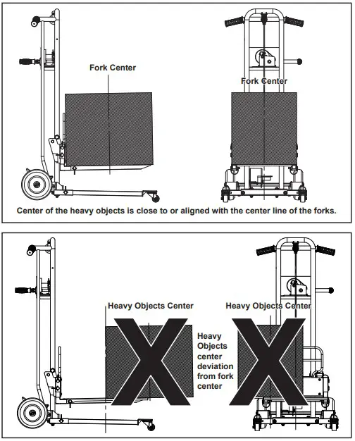
Operation of the brake mechanism
a. When moving the lift, make sure the brake device of the lift is in the off position. the operation method is: press the pedal with your foot to release the break, as shown below (See Fig. A)
b. When the lift truck is stopped or parked for a long time, in order to avoid the risk caused by the sliding of the lift truck, the brake device needs to be in the engaged position, and the operation method is: press the brake pedal with your foot. (See Fig. B)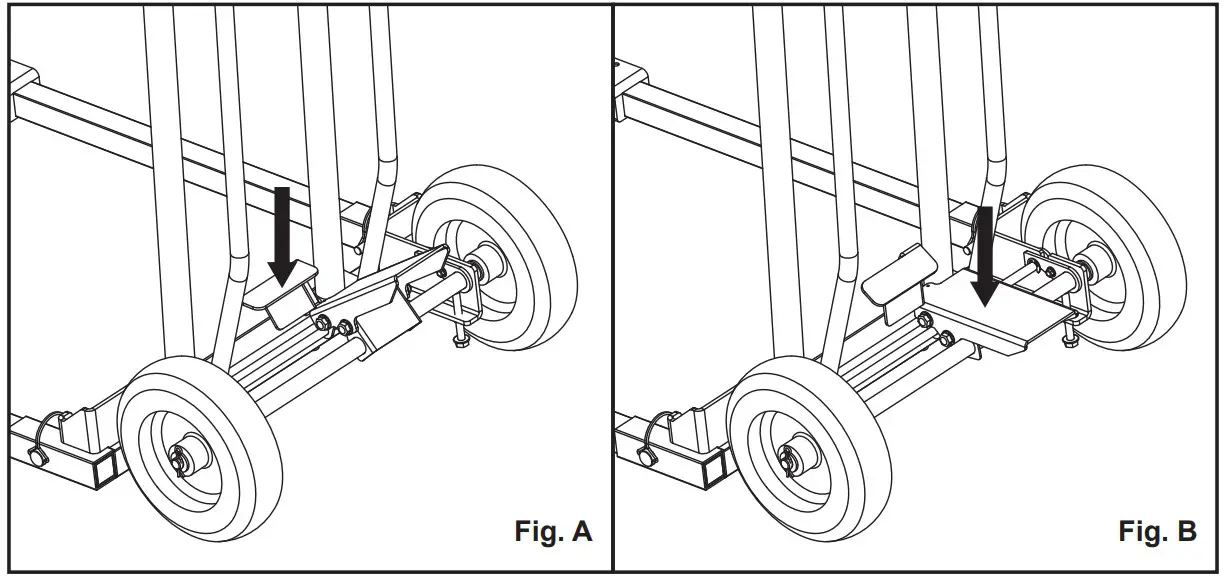
Heavy Objects handling
Basic operations
a. Place the heavy objects on the lift, see 7.1 for details of placement.
b. Before moving the lift, make sure the brakes of the lift are released. When the lift is stopped or parked for a long time, the brakes should be in the braking state (see 7.2 for details of operation).
Tilt operation
If the lift truck carries heavy objects within 60kg, in order to increase the driving speed and improve the working efficiency, the lift truck (including the heavy objects) can be tilted at a suitable angle and operated in the following way
a. Fork height from the base not exceeding 200 mm.
b. Holding the armrest position with both hands.
c. Hold the wheel axle of the base with the foot and use both hands to tilt the lift back at the right angle.
d. Maintain the proper angle of backward tilt and drag the lift to travel.
e. Step on the wheel axle of the base with your foot and slowly put down the lift until all four wheels touch the ground.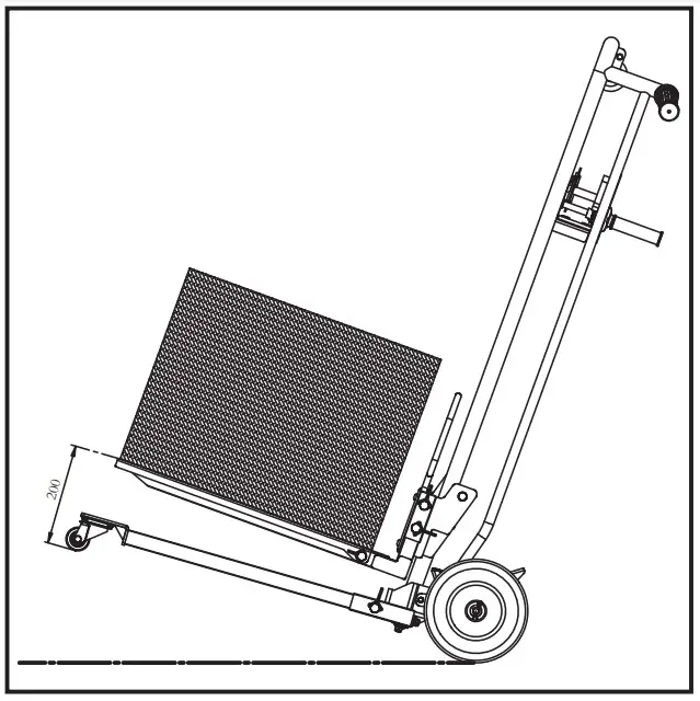
Positioning pin operation
To prevent the forks from sliding when handling the lift, please screw the star bolt into the hole of the tube to fix the forks. Please loosen the star bolt when you need to lift.
Folding handle operation
Folding operations.
a. Pull the handle outward for a short distance.
b. Then turn the handle to the inside, you can complete the folding operation.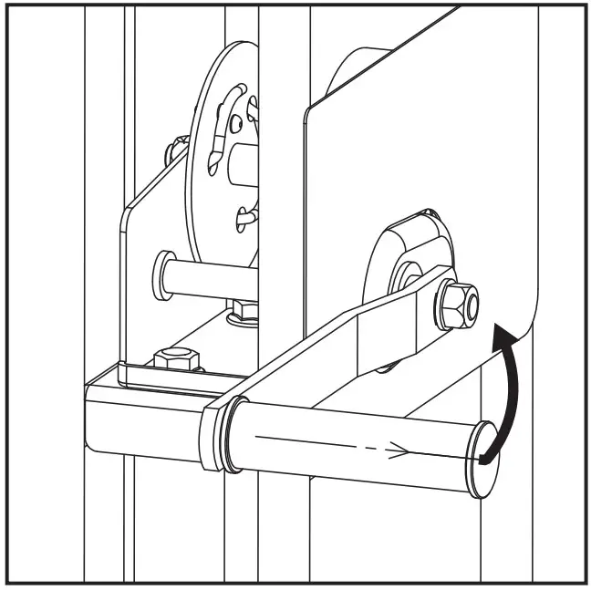
MAINTENANCE
Directional wheel replacement
a. First pull out the R-pin from the axle hole, take out the washer, and then use a rubber hammer to knock the directional wheel out of the axle.
b. Insert the replacement directional wheel into the axle in place, install the washer and then insert the R-pin into the axle hole.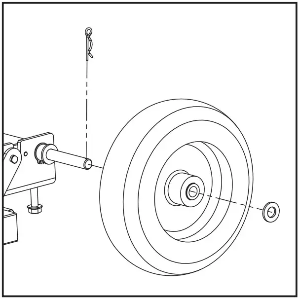
Universal Wheel Replacement
a. Loosen the four M5 locknuts first, then remove the universal wheel.
b. After replacing the universal wheel, tighten the four M5 lock nuts.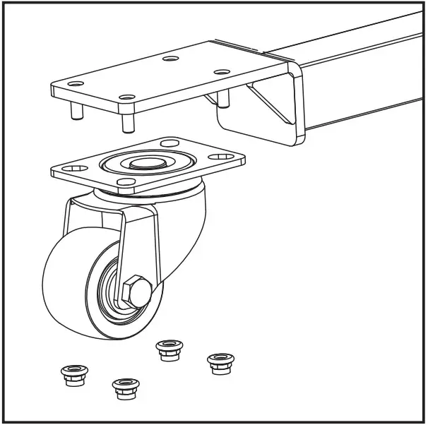
Pulley replacement
a. Remove the retaining ring from the pin, and then pull out the pin.
b. Using the new pulley, place the nylon rope in the groove of the pulley and place the pulley at the installation position, put the pins in order and use the tool to put the retaining ring into the pins to complete the replacement of the pulley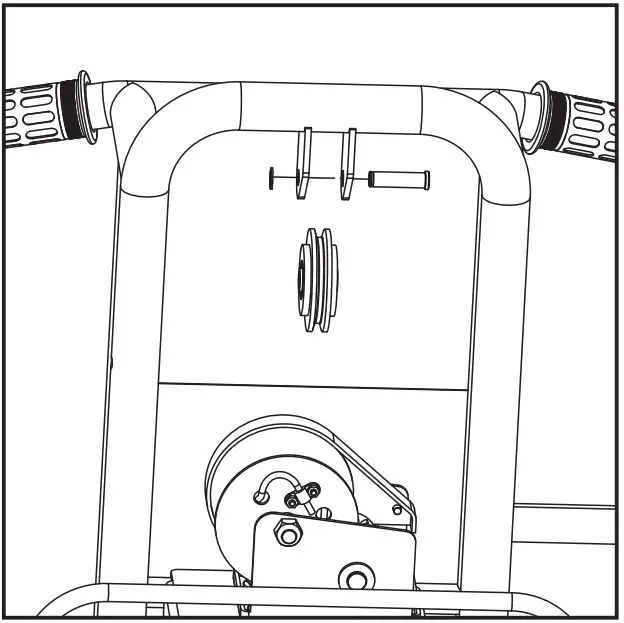
Flat plate replacement
a. Shake the winch handle, the forks (including flat) to the right position (convenient to replace the height of the plate is appropriate).
b. Take out the D-pins on both sides and remove the flat plate respectively.
c. Place the replacement plate on the forks and insert the D-pins into the pin holes of the forks and plate on both sides respectively (lock them) to complete the plate replacement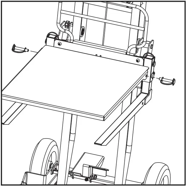
Fork replacement
a. Remove the D-pins from each side and pull out the forks in the downward direction.
b. Insert the new fork into the mounting interface and insert the D-pins into the pin holes and lock them respectively.
c. Replace the fork on the other side according to the above steps.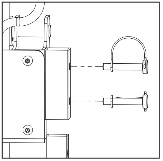
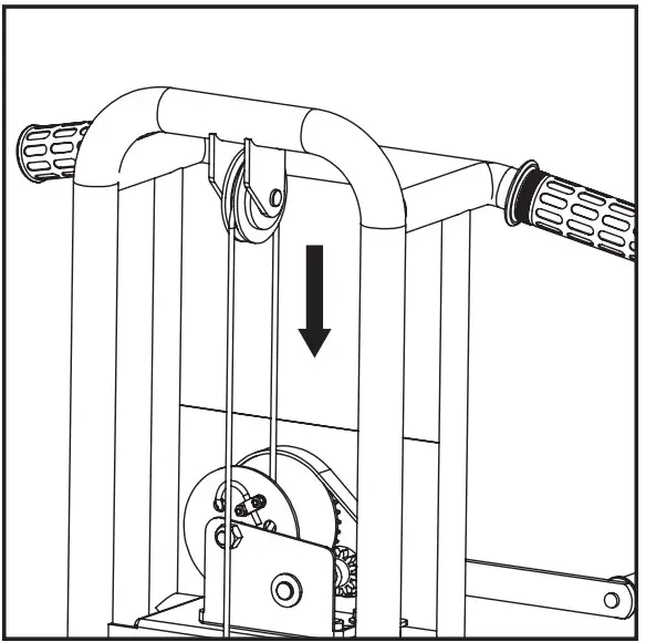
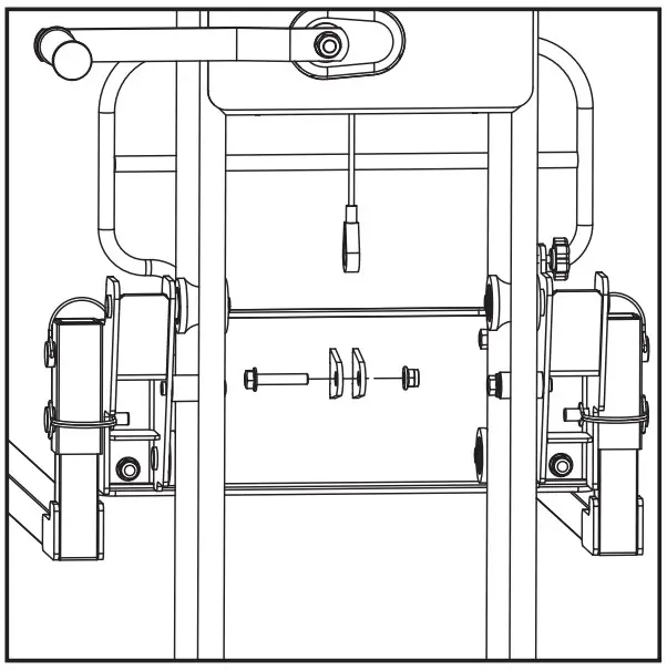
Nylon rope replacement
Note: Before replacing the nylon rope, make sure the fork in the lowest position, for safety reasons, it is recommended to make the nylon rope in the loose state.
a. Disassembly of nylon rope.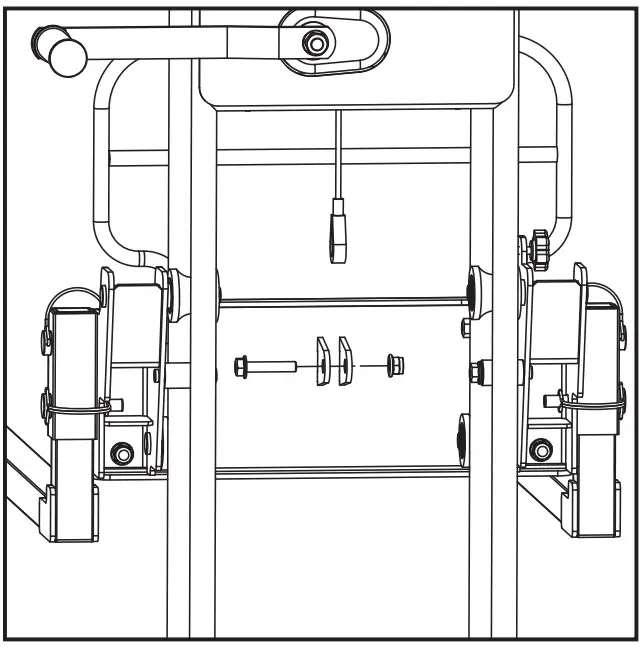
- Disassembly of nylon rope and support plate: first unscrew the nut, pull the wire rope with your hand, and pull out the s crew with the other hand.
- Disassembly of nylon rope and winch.
- Loosen the 2 nuts first and remove the platen.
- The nylon rope in turn from the winch hole C, hole B and hole A pull out, pull out the process needs to be operated carefully to avoid the elasticity of the nylon rope injury
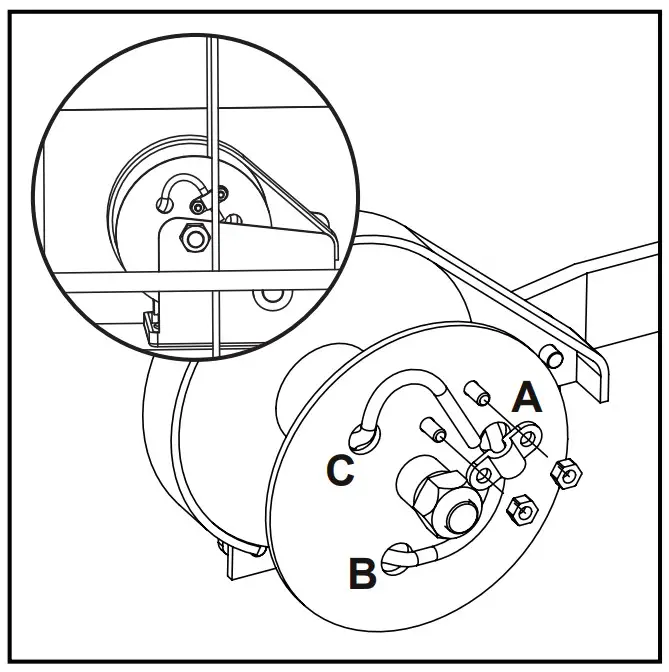
- Remove the nylon rope from the winch shaft and pull it out from the pulley to complete the removal of the nylon rope.
b. Installation of nylon rope.
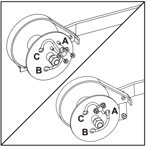
- Installation of nylon rope and winch. First insert the nylon rope (unbuckled end) into the groove of the pulley first.
- Thread the nylon rope through hole A (inside-out), hole B (outside-in) and hole C (inside-out) of the winch in turn and place the end of the nylon rope between the two screw holes.
- Two screws into the screw holes (from inside to outside), the pressure plate into the screws and press the nylon rope, tighten the nut, complete the nylon rope and winch installation.
- Nylon rope and support plate installation: the fork is in the lowest position, pull the other end of the nylon rope by hand, so that the press button through hole and the support plate installation hole concentric alignment, screws into the hole and lock the nut, that is, the completion of the installation of nylon rope.
TRANSPORTATION&STORAGE
- When storing the product, it should be stored in a cool, dry and dust-free place, avoiding direct sunlight and rain.
- When transporting, loading and unloading the products, it is strictly prohibited to throw, drop, throw, and trample and other barbaric operations.
WARRANTY
Twelve (12) months for workmanship of the product, except for wearing parts. Warranty period starts from the product purchase date. Warranty covers material quality and workmanship only. Warranty does not cover product for issues caused by improper usage or any operation not in accordance with the specifications of this manual. Any modification or tampering with the product in any way voids the warranty
TROUBLE SHOOTING
- Normal maintenance and regular servicing will extend the life of the equipment.
- The following troubleshooting guide lists the most common problems, causes and solutions.
| Problem(s) | Possible Cause | Corrective Action |
| Abnormal noise or jamming when the winch handle is rotating |
|
|
| The lift does not move smoothly or has strange noises. |
|
|
EXPLODED VIEW AND PARTS LIST
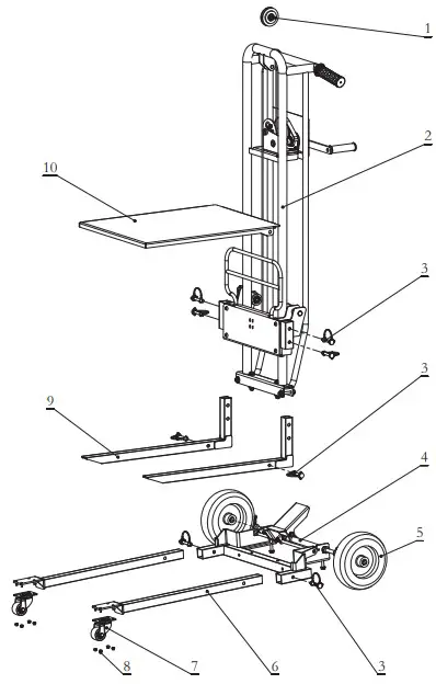
| Part No. | Description | Q’ty |
| 1 | Nylon rope pulley | 1 |
| 2 | Primary frame | 1 |
| 3 | D-pin | 8 |
| 4 | Base | 1 |
| 5 | Directional wheel | 2 |
| 6 | Wheel carrier | 2 |
| 7 | Universal wheel | 2 |
| 8 | Nut | 8 |
| 9 | Fork | 2 |
| 10 | Flat plate | 1 |
Great Circle USA
Support Line: 1-866-493-0524
[email protected]
www.greatcircleus.com